1 INTRODUCTION
The application of stainless steel as a structural material has been increasing, due to a number of desirable qualities such as its durability, resistance to corrosion and aesthetic appearance (Gard-ner, L., 2005 & Euro Inox, 2006). Despite having a high initial cost, stainless steel can be a com-petitive material if life cycle cost analysis is considered, due to its low maintenance needs. More-over, it has a higher fire resistance when compared to carbon steel (CEN, 2005b) allowing in some cases the absence of thermal protection.
The austenitic stainless steels are generally the most used groups for structural applications but some interest has being recently shown for increasing the use of ferritic and austenitic-ferritic (Duplex) steels for structural purposes due to specific advantages. Some of those advantages are the very good resistance to wear and stress corrosion cracking of the duplex grade and the lower percentage of Nickel of the ferritic grade, which reduces its price.
Regarding structural fire resistance, in order to have a comprehensive understanding of the overall members’ resistance, it is important to first analyse the cross-section resistance, which is directly affected by local instabilities occurrence on the composed thin plates.
For structural design purposes, Eurocode 3 (EC3) (CEN, 2006a) considers that the walls slen-derness determine the cross-section classification (from Class 1 - stocky sections to Class 4 - slender sections). Subsequently, the cross-section resistance is calculated considering plastic sec-tion properties for Classes 1 and 2 secsec-tions, elastic secsec-tion properties for Class 3 secsec-tions and effective section properties, applying the effective width method, for Class 4 sections. In addition, for cross-section of Classes 1, 2 and 3 at elevated temperatures the strength at 2% total strain should be considered as the yield strength and for Class 4 cross-sections it should be applied the 0.2% proof strength (CEN, 2005b).
Although the subject of local buckling at elevated temperatures has been studied by different authors (Couto et al., 2014, Couto et al., 2015, FIDESC4, 2014, Knobloch & Fontana, 2006, Maraveas et at., 2017, Quiel & Garlock, 2010), the mentioned research works only address carbon
Behaviour of slender plates in case of fire of different stainless
steel grades
F. Arrais
RISCO — Civil Engineering Department, University of Aveiro, Portugal
N. Lopes
RISCO — Civil Engineering Department, University of Aveiro, Portugal
P. Vila Real
RISCO — Civil Engineering Department, University of Aveiro, Portugal
C. Couto
RISCO — Civil Engineering Department, University of Aveiro, Portugal
ABSTRACT: Stainless steel has countless desirable characteristics for a structural material. Alt-hough initially more expensive than conventional carbon steel, stainless steel structures can be competitive because of their smaller or none need for thermal protection material and lower life-cycle cost, thus contributing to a more sustainable construction. Regarding structural fire re-sistance, in order to have a comprehensive understanding of the overall members’ rere-sistance, it is important to first analyse the cross-section resistance, directly affected by local instabilities oc-currence on the composed thin plates. This work presents a numerical study on the behaviour of isolated plates at elevated temperatures, corresponded to the web (internal element) and flanges (outstand element) of I-cross sections, comparing the numerically obtained ultimate load bearing capacities with simplified calculation formulae for the application of the effective width method. Comparisons between the numerical results and the EC3 formulae for determining the effective area of thin plates is also presented.
steel elements and research of the local buckling effect on stainless steel sections at elevated tem-peratures is scarce and mostly focus on the member behaviour.
According to Part 1-2 of EC3 (CEN, 2005b) design rules, stainless steel stress-strain relation-ships at elevated temperatures are characterized by having an always non-linear behaviour with an extensive hardening phase, when compared with carbon steel constitutive law. As existing fire design guidelines for stainless steel, such as in EN 1993-1-2 (CEN, 2005b), are based on the formulations developed for carbon steel members (CEN, 2005a, CEN, 2006b), in spite of their different material behaviour, it is still necessary to develop knowledge on stainless steel structural behaviour at elevated temperatures.
This research work has the main objective of analysing the accuracy of EC3 present calculation proposals for stainless steel cross-sections in case of fire, subjected to compression or bending, by means of Geometrical and Material Non-linear Analysis with Imperfections applying the Finite Element software SAFIR (Franssen & Gernay, 2017). Plates behaviour at elevated temperatures is analysed considering compression or bending and different boundary conditions for modelling isolated outstand elements (flanges) and internal elements (webs), following the methodology used for the development of carbon steel design approaches (Couto et al., 2014, FIDESC4, 2014, CEN, 2006b). In this parametric study, as different stainless steel grades exibit different stress-strain relationships behaviours at elevated temperatures (CEN, 2005b), the following grades were considered: i) 1.4301 (Austenitic grade); ii) 1.4003 (Ferritic grade); iii) 1.4462 (duplex).
Comparisons between the obtained numerical results, the EC3 design methods and a recent proposal for Class 4 carbon steel sections (Couto et al., 2015), are made, being concluded that new design expressions should be developed for the effective with method application on stainless steel I-sections subjected to fire.
2 SIMPLIFIED DESIGN RULES 2.1 Eurocode3
According to EN 1993-1-2 (CEN, 2005b), the section resistance of a stainless steel member in case of fire is calculated in the same way as for carbon steel, changing only the mechanical prop-erties of the material to consider uniform elevated temperatures in the section.
Regarding the cross-section classification, Equation 1 was used to determine the factor 𝜀, a parameter necessary for the determination of the EC3 classification limits (Franssen & Vila Real, 2015). 𝜀𝜃= 0.85 [ 235 𝑓𝑦 𝐸 210000] 0.5 (1)
The design resistance value of axially compressed members of Class 1, 2 or 3 cross-sections with a uniform temperature 𝜃𝑎 is determined from Equation 2.
𝑁𝑓𝑖,𝑡,𝑅𝑑 = 𝐴 𝑓𝑦,𝜃 γ⁄ M,fi (2)
For Class 4 sections, according to Annex E of EN 1993-1-2, the effective area (𝐴𝑒𝑓𝑓), obtained
from EN 1993-1-5 (CEN, 2006b), should be considered instead of the gross cross-section area 𝐴. In a fire situation higher strains are acceptable when compared to normal temperature design, therefore, instead of 0.2% proof strength usually considered at normal temperature, for cross-section of classes 1, 2 and 3 at elevated temperatures the stress corresponding to 2% of total strain should be adopted as the yield strength (CEN, 2005b).
𝑓𝑦,𝜃= 𝑓2%,𝜃 = 𝑘2%,𝜃𝑓𝑦 (3)
However, for Class 4 cross-sections, according to Annex E of EN 1993-1-2, the proof strength at 0.2% strain should be used, thus
The mentioned reduction factors are given on Annex C of EN 1993-1-2 for stainless steel at high temperatures for the different analysed stainless steel grades.
In beams, the design value of the bending moment resistance of a cross-section with a uniform temperature 𝜃𝑎 is determined from:
𝑀𝑓𝑖,𝜃,𝑅𝑑 = 𝑘𝑦,𝜃[γM,0⁄γM,fi]𝑀𝑐,𝑅𝑑 (5)
Being 𝑀𝑐,𝑅𝑑 for Classes 1 and 2 the plastic bending moment capacity, for Class 3 the elastic bending moment capacity, and for Class 4 sections the effective bending moment capacity, at normal temperature, determined with the effective section properties obtained from EN 1993-1-5. The effective area and effective section modulus (𝑊𝑒𝑓𝑓,𝑦) are determined through the application
of the effective width method, considering the reduction of resistance due to local buckling effects (CEN, 2006b). On this regard, the EN 1993-1-4 (CEN, 2006a) provides specific equations for the determination of the plate reduction factors (𝜌) to the width of elements composing the stainless steel sections, as presented in Equation 6 and Table 1. It can be observed that the reduction factor for internal elements do not depend on the stress distribution as proposed in carbon steel plates (CEN, 2005a).
𝑏𝑒𝑓𝑓= 𝜌. 𝑏 (6)
Table 1. Reduction factor for stainless steel sections elements.
Cross-section elements Reduction factor
Welded outstand elements 𝜌 =
1
λ̅p
−0.242
λ̅p2
≤ 1
Welded internal elements 𝜌 =0.772
λ̅p
−0.125
λ̅p2
≤ 1
The plate slenderness – λ̅p – value is determined with Equation 7.
λ̅p= √
fy
σcr
= b̅ t⁄
28.4 ε √kσ (7)
2.2 Proposal for Class 4 carbon steel sections at elevated temperatures
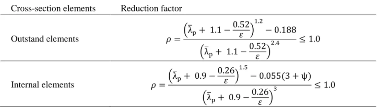
As mentioned before, recent research works (Couto et al., 2015, Knobloch & Fontana, 2006) proposed the use of the stress corresponding to 2% of total strain as the steel yield strength also for Class 4 cross-sections at elevated temperatures, as it is done for the remaining sections, provid-ing the plate reduction factors would be calculated as presented in Table 2. The accuracy of the application of this proposal for stainless steel sections is tested in this paper.
Table 2. Reduction factor proposed for carbon steel sections elements in case of fire (Couto et al., 2015).
Cross-section elements Reduction factor
Outstand elements 𝜌 =(λ̅p+ 1.1 − 0.52 𝜀 ) 1.2 − 0.188 (λ̅p+ 1.1 − 0.52 𝜀 ) 2.4 ≤ 1.0 Internal elements 𝜌 =(λ̅p+ 0.9 − 0.26 𝜀 ) 1.5 − 0.055(3 + ψ) (λ̅p+ 0.9 − 0.26 𝜀 ) 3 ≤ 1.0
3 PLATES BEHAVIOUR 3.1 Numerical modelling
Members composed of different cross-section shapes may exibit diferent plates behaviour. For instance in I-shape sections subjected to compression have both flanges and web in compression, whereas when the members are subjected to bending in the strong axis, a flange is in compression while the web is subjected to bending. Rectangular hollow sections subjected to compression will have only internal elements subjected to compression and when subjected to bending will have an internal element subjected to compression and others internal elements subjected to bending.
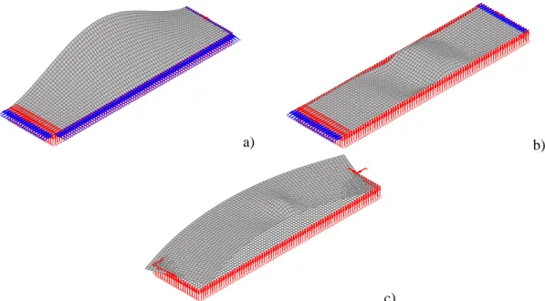
To determine the ultimate load of rectangular plates the program SAFIR was used. Each shell element has four nodes with six degrees of freedom (three translations and three rotations). Simply supported conditions where applied to the plates by restraining the vertical displacements, in ad-dition the rotations at the edges of the plate were also restrained to simulate the web-flange con-tinuity. For the outstand elements, the vertical displacements were restrained on three sides while for the internal elements the vertical displacements were restrained in all four sides, this method-ology follows the same principles as in Couto et al., (2014). Figure 1 presents the obtained de-formed shapes of an outstand element subjected to compression, an internal element subjected to compression and an internal element subjected to bending.
Geometric imperfections were introduced into the numerical model by changing the nodal co-ordinates affine to the buckling mode shapes obtained with the program CAST3M (CEA, 2012) and applying the interface RUBY (Couto et al., 2013). For the amplitude of the imperfections, it was considered 80% of b/50 for outstand elements and 80% of b/100 for internal elements, fol-lowing the recommendations of EN 1090-2 (CEN, 2011). Plates of the stainless steel grade 1.4301, 1.4003 and 1.4462 (CEN, 2006a) subjected to four temperatures were considered 350ºC, 400ºC, 450ºC and 500ºC (common critical temperatures in slender sections).
a) b)
c)
Figure 1. Deformed shapes (x5): a) outstand element subjected to compression; b) internal element sub-jected to compression; c) internal element subsub-jected to bending.
The nominal values applied of yield strength, ultimate strength and elastic modulus of stainless steel in the numerical models are presented in Table 3.
Table 3. Nominal values for different stainless steel grades (CEN, 2006a).
Type Grade Yield strength 𝑓𝑦 (MPa) Ultimate strength 𝑓𝑢 (MPa) Elastic modulus 𝐸 (GPa)
Austenitic 1.4301 210 520 200 Ferritic 1.4003 280 450 220 Duplex 1.4462 460 660 200 F0 F0 F0 F0 F0 F0 F0 F0 F0 F0 F0 F0 F0 F0 F0 F0 F0 F0 F0 F0 F0 F0 F0 F0 F0 F0 F0 F0 F0 F0 F0 F0 F0 F0 F0 F0 F0 F0 F0 F0 F0 F0 F0 F0 F0 F0 F0 F0 F0 F0 F0 F0 F0 F0 F0 F0 F0 F0 F0 F0 F0 F0 F0 F0 F0 F0 F0 F0 F0 F0 F0 F0 F0 F0 F0 F0 F0 F0 F0 F0 F0 F0 F0 F0 F0 F0 F0 F0 F0 F0 F0 F0 F0 F0 F0 F0 F0 F0 F0 F0 F0 F0 F0 F0 F0 F0 F0 F0 F0 F0 F0 F0 F0 F0 F0 F0 F0 F0 F0 F0 F0 F0 F0 F0 F0 F0 F0 F0 F0 F0 F0 F0 F0 F0 F0 F0 F0 F0 F0 F0 F0 F0 F0 F0 F0 F0 F0 F0 F0 F0 F0 F0 F0 F0 F0 F0 F0 F0 F0 F0 F0 F0 F0 F0 F0 F0 F0 F0 F0 F0 F0 F0 F0 F0 F0 F0 F0 F0 F0 F0 F0 F0 F0 F0 F0 F0 F0 F0 F0 F0 F0 F0 F0 F0 F0 F0 F0 F0 F0 F0 F0 F0 F0 F0 F0 F0 F0 F0 F0 F0 F0 F0 F0 F0 F0 F0 F0 F0 F0 F0 F0 F0 F0 F0 F0 F0 F0 F0 F0 F0 F0 F0 F0 F0 F0 F0 F0 F0 F0 F0 F0 F0 F0 F0 F0 F0 F0 F0 F0 F0 F0 F0 F0 F0 F0 F0 F0 F0 F0 F0 F0 F0 F0 F0 F0 F0 F0 F0 F0 F0 F0 F0 F0 F0 F0 F0 F0 F0 F0 F0 F0 F0 F0 F0 F0 F0 F0 F0 F0 F0 F0 F0 F0 F0 F0 F0 F0 F0 F0 F0 F0 F0 F0 F0 F0 F0 F0 F0 F0 F0 F0 F0 F0 F0 F0 F0 F0 F0 F0 F0 F0 F0 F0 F0 F0 F0 F0 F0 F0 F0 F0 F0 F0 F0 F0 F0 F0 F0 F0 F0 F0 F0 F0 F0 F0 F0 F0 F0 F0 F0 F0 F0 F0 F0 F0 F0 F0 F0 F0 F0 F0 F0 F0 F0 F0 F0 F0 F0 F0 F0 F0 F0 F0 F0 F0 F0 F0 F0 F0 F0 F0 F0 F0 F0 F0 F0 F0 F0 F0 F0 F0 F0 F0 F0 F0 F0 F0 F0 F0 F0 F0 F0 F0 F0 F0 F0 F0 F0 F0 F0 F0 F0 F0 F0 F0 F0 F0 F0 F0 F0 F0 F0 F0 F0 F0 F0 F0 F0 F0 F0 F0 F0 F0 F0 F0 F0 F0 F0 F0 F0 F0 F0 F0 F0 F0 F0 F0 F0 F0 F0 F0 F0 F0 F0 F0 F0 F0 F0 F0 F0 F0 F0 F0 F0 F0 F0 F0 F0 F0 F0 F0 F0 F0 F0 F0 F0 F0 F0 F0 F0 F0 F0 F0 F0 F0 F0 F0 F0 F0 F0 F0 F0 F0 F0 F0 F0 F0 F0 F0 F0 F0 F0 F0 F0 F0 F0 F0 F0 F0 F0 F0 F0 F0 F0 F0 F0 F0 F0 F0 F0 X Y Z -5.0 E-01 m
Diamond 2011.a.2 for S AFIR
FILE: 10.0mmimp NODES: 1701 BEAMS: 0 TRUSSES: 0 SHELLS: 1600 SOILS: 0
IMPOSED DOF PLOT DISPLACEMENT PLOT ( x -0.75) TIME: 2790.1 sec F0 F0 F0F0 F0 F0 F0F0 F0 F0 F0 F0 F0 F0 F0 F0 F0 F0 F0 F0 F0 F0 F0 F0 F0 F0 F0 F0 F0 F0 F0 F0 F0 F0 F0 F0 F0 F0 F0 F0 F0 F0 F0 F0 F0 F0 F0 F0 F0 F0 F0 F0 F0 F0 F0 F0 F0 F0 F0 F0 F0 F0 F0 F0 F0 F0 F0 F0 F0 F0 F0 F0 F0 F0 F0 F0 F0 F0 F0 F0 F0 F0 F0 F0 F0 F0 F0 F0 F0 F0 F0 F0 F0 F0 F0 F0 F0 F0 F0 F0 F0 F0 F0 F0 F0 F0 F0 F0 F0 F0 F0 F0 F0 F0 F0 F0 F0 F0 F0 F0F0 F0 F0 F0 F0F0 F0 F0 F0F0 F0 F0 F0F0 F0 F0 F0F0 F0 F0 F0F0 F0F0 F0 F0 F0F0 F0 F0 F0F0 F0 F0 F0F0 F0 F0 F0F0 F0 F0 F0F0 F0 F0 F0F0 F0 F0 F0F0 F0 F0 F0F0 F0 F0 F0F0 F0 F0 F0F0 F0 F0 F0 F0 F0F0 F0 F0 F0F0 F0 F0 F0F0 F0 F0 F0F0 F0 F0 F0F0 F0 F0 F0F0 F0 F0 F0 F0 F0F0 F0 F0 F0F0 F0 F0 F0F0 F0 F0 F0F0 F0 F0 F0F0 F0 F0 F0F0 F0 F0 F0F0 F0 F0 F0F0 F0 F0 F0F0 F0 F0 F0F0 F0F0 F0 F0 F0F0 F0 F0 F0F0 F0 F0 F0F0 F0 F0 F0F0 F0 F0 F0F0 F0 F0 F0F0 F0F0 F0 F0 F0F0 F0 F0 F0F0 F0 F0 F0F0 F0 F0 F0F0 F0 F0 F0F0 F0 F0 F0F0 F0 F0 F0F0 F0 F0 F0F0 F0 F0 F0F0 F0 F0 F0F0 F0 F0 F0F0 F0 F0 F0F0 F0 F0 F0 F0 F0F0 F0 F0 F0F0 F0 F0 F0F0 F0 F0 F0F0 F0 F0 F0F0 F0 F0 F0F0 F0 F0 F0F0 F0 F0 F0 F0 F0 F0 F0 F0F0 F0 F0 F0 F0 F0 F0 F0F0 F0 F0 F0 F0 F0 F0 F0F0 F0 F0 F0 F0 F0 F0 F0F0 F0 F0 F0 F0 F0 F0 F0F0 F0 F0 F0 F0 F0 F0 F0F0 F0 F0 F0 F0 F0 F0 F0F0 F0 F0 F0 F0 F0 F0 F0F0 F0 F0 F0 F0 F0 F0 F0F0 F0 F0 F0 F0 F0 F0 F0 F0F0 F0 F0 F0 F0 F0 F0 F0 F0F0 F0 F0 F0 F0 F0 F0 F0F0 F0 F0 F0 F0 F0 F0 F0F0 F0 F0 F0 F0 F0 F0 F0F0 F0 F0 F0 F0 F0 F0 F0F0 F0 F0 F0 F0 F0 F0 F0F0 F0 F0 F0 F0 F0 F0 F0F0 F0 F0 F0 F0 F0 F0 F0F0 F0 F0 F0 F0 F0 F0 F0F0 F0 F0 F0 F0 F0 F0 F0 X Y Z 1.0 E-01 m
Diamond 2011.a.2 for S AFIR
FILE: Lmm NODES: 1701 BEAMS: 0 TRUSSES: 0 SHELLS: 1600 SOILS: 0
IMPOSED DOF PLOT DISPLACEMENT PLOT ( x 2) TIME: 1716.422 sec F0 F0F0 F0 F0F0F0 F0 F0 F0 F0 F0 F0 F0F0F0F0 F0 F0 F0 F0 F0 F0 F0 F0 F0F0 F0 F0 F0 F0 F0 F0 F0F0F0 F0 F0 F0 F0 F0 F0 F0 F0 F0 F0F0 F0 F0 F0F0 F0 F0 F0 F0 F0 F0 F0F0 F0 F0 F0 F0 F0F0 F0 F0 F0 F0 F0F0F0 F0 F0 F0 F0 F0 F0F0 F0 F0 F0 F0F0 F0 F0 F0F0 F0 F0 F0F0F0F0 F0 F0 F0 F0 F0F0 F0 F0 F0F0 F0 F0 F0F0 F0 F0 F0F0 F0 F0 F0F0 F0 F0 F0F0 F0F0 F0 F0 F0F0 F0 F0 F0F0 F0 F0 F0F0 F0 F0 F0 F0 F0F0 F0 F0 F0F0 F0F0 F0 F0 F0F0 F0 F0 F0F0 F0 F0 F0 F0 F0F0 F0F0 F0 F0 F0F0 F0 F0 F0F0 F0 F0 F0 F0 F0F0 F0 F0 F0F0 F0F0 F0 F0 F0 F0 F0F0 F0 F0 F0F0 F0 F0 F0F0 F0 F0 F0F0 F0 F0 F0F0 F0F0 F0 F0 F0F0 F0 F0 F0 F0 F0F0F0F0 F0 F0 F0F0 F0 F0 F0F0 F0 F0 F0F0 F0 F0 F0F0 F0 F0 F0 F0 F0F0 F0 F0 F0F0 F0F0 F0 F0 F0F0 F0 F0 F0F0 F0 F0 F0 F0 F0F0 F0 F0 F0F0 F0 F0 F0F0 F0F0 F0 F0 F0 F0 F0F0 F0 F0 F0F0 F0F0 F0 F0 F0 F0 F0F0 F0F0 F0 F0 F0F0 F0 F0 F0F0 F0 F0 F0 F0 F0F0 F0 F0 F0F0 F0F0 F0 F0 F0 F0 F0F0 F0F0 F0 F0 F0 F0F0 F0F0 F0F0 F0 F0 F0F0F0 F0F0 F0 F0F0 F0F0 F0F0 F0F0 F0 F0 F0F0 F0F0F0F0 F0F0 F0F0 F0 F0 F0F0 F0 F0 F0 F0 F0 F0 F0F0 F0F0F0F0F0 F0F0F0F0 F0 F0F0 F0F0 F0F0 F0F0 F0 F0 F0F0 F0F0F0 F0 F0F0 F0F0F0F0F0F0F0 X Y Z 1.0 E-02 m
Diamond 2011.a.2 for S AFIR
FILE: Lmm NODES: 1701 BEAMS: 0 TRUSSES: 0 SHELLS: 1600 SOILS: 0 SHELLS PLOT IMPOSED DOF PLOT DISPLACEMENT PLOT ( x 20)
TIME: 716.0203 sec Shell Element
These mechanical properties are reduced at elevated temperatures as presented in Figure 2, which vary for each grade.
a) b)
Figure 2. Mechanical properties reduction at elevated temperatures (CEN, 2005b): a) yield strength re-tention; b) young modulus reduction.
3.2 Plates subjected to compression
The results obtained for outstand and internal plate elements subjected to compression are here presented. At elevated temperatures, the equation to determine the reduction factor has to be adapted due to the transition that occurs from Class 3 to Class 4 section because of the change on the limit strength, leading to a discontinuity in the curve, as presented in Equation 8.
𝜌𝜃=𝑁𝑐,𝑅𝑑
𝑁𝑅𝑑 = 𝜌
𝑓𝑦,𝜃
𝑓2,𝜃
(8) Figure 3 to 5 presents the comparisons between the ultimate load bearing capacities, for out-stand and internal plate elements subjected to compression, obtained with EC3, the new proposal for Class 4 carbon steel elements (“CS New Proposal” in the chart) and SAFIR.
a) b)
Figure 3. Results for a) outstand elements and b) internal elements subjected to compression for austenitic stainless steel at elevated temperatures.
a) b)
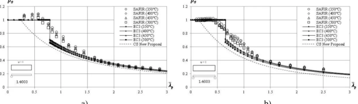
Figure 4. Results for a) outstand elements and b) internal elements subjected to compression for ferritic stainless steel at elevated temperatures.
0 0.2 0.4 0.6 0.8 1 0 200 400 600 800 1000 1200 kE,q q (ºC) Stainless steel Carbon steel comLT ,,q
a) b)
Figure 5. Results for a) outstand elements and b) internal elements subjected to compression for aus-tenitic-ferritic (Duplex) stainless steel at elevated temperatures.
For both outstand and internal elements subjected to compression, the proposal for carbon steel Class 4 sections (Couto et al., 2014) eliminates the un-conservative nature given by the plateau of EC3 for austenitic (Figure 3) and ferritic stainless steel (Figure 4). The results for austenitic-ferritic stainless steel (Figure 5) revealed that the rules are over conservatives. Nonetheless, the results highlight the need of improved design equations specifically developed for stainless steel plates subjected to compression at elevated temperatures, considering the stainless steel grade.
3.3 Plates subjected to bending
The obtained results for internal plate elements subjected to bending are presented in Figure 6. The ultimate bending moments obtained in each plate for all methods were divided by the plastic bending moments.
a) b)
c)
Figure 6. Results for internal elements subjected to bending for a) austenitic, b) ferritic and c) austenitic-ferritic (Duplex) stainless steel at elevated temperatures.
The different plateaus, in this figure, observed in Eurocode procedure of EN 1993-1-4 corre-spond to the transitions between Class 2 and Class 3 sections (from plastic to elastic resistance) and from Class 3 to Class 4 where at elevated temperatures the yield strength changes, as men-tioned before. The curves from both proposals are over conservative when compared with the
numerical results, which leads to conclude that specific formulae for stainless steel plates should be developed, which can be observed specifically for austenitic-ferritic stainless steel.
3.4 Statistical analysis
The average value (μ) and the standard deviation (s) are important values to take into account in the statistical analysis for the different methodologies of EC3 and different Proposals. For each stainless steel grade and for each analysed curve it is possible to evaluate the ratio between the analytical value and the corresponding SAFIR (Figure 7 and 8).
a) b) c)
Figure 7. Comparison between EN 1993-1-4 and SAFIR – Grades a) 1.4301, b) 1.4003 and c) 1.4462
a) b) c)
Figure 8. Comparison between CS New Proposal and SAFIR – Grades a) 1.4301, b) 1.4003, c) 1.4462
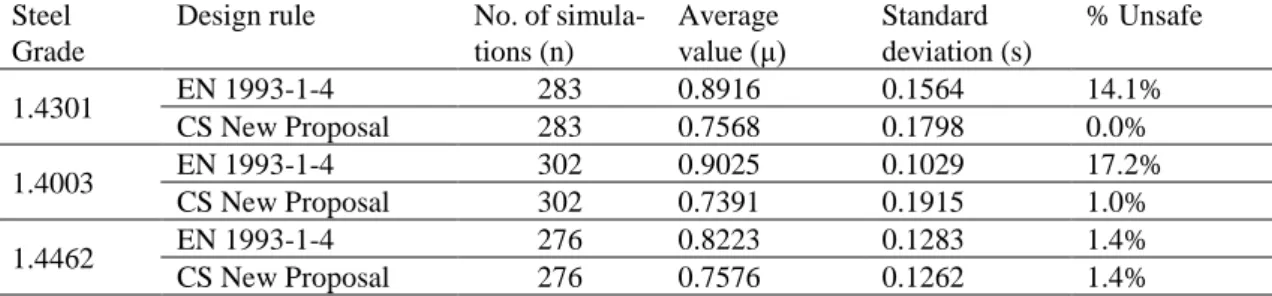
From Figure 7 and 8 and Table 4 it is possible to observe that the different design rules are not adapted for stainless steel thin plates with low average values and high standard deviations. The number of unsafe results is also relevant for the accuracy of these design rules.
Table 4. Statistical evaluation for different stainless steel grades at high temperatures
Steel Grade
Design rule No. of
simula-tions (n) Average value (μ) Standard deviation (s) % Unsafe 1.4301 EN 1993-1-4 283 0.8916 0.1564 14.1% CS New Proposal 283 0.7568 0.1798 0.0% 1.4003 EN 1993-1-4 302 0.9025 0.1029 17.2% CS New Proposal 302 0.7391 0.1915 1.0% 1.4462 EN 1993-1-4 276 0.8223 0.1283 1.4% CS New Proposal 276 0.7576 0.1262 1.4% 4 CONCLUSIONS
This work presented a numerical study regarding the plates’ behaviour of different stainless steel grades (austenitic, ferritic and austenitic-ferritic (Duplex) stainless steel), composing the cross-sections of members in fire situation.
In order to better understand the behaviour of these stainless steel sections, thin plates at ele-vated temperatures were analysed. This study, on compressed outstand elements, compressed in-ternal elements and inin-ternal elements subjected to bending, concluded that EC3 does not provide accurate and safe approximations to their numerically obtained counterparts regarding the ulti-mate load bearing capacities. Following this conclusion, a recent proposal for carbon steel plates (Couto et al., 2014) was also investigated. It was observed that using this proposal allowed to overcome the unsafety that was previously observed for Class 3 sections, but results remained too conservative for Class 4 sections.
In summary, the prediction of the resistance of stainless steel members for the case of fire is still not completely understood, thus motivating and justifying the development of more studies with the objective to achieve more precise and safe formulations for these members.
ACKNOWLEDGEMENTS
This research work was performed within the framework of the project “Fire design of stainless steel members” - StaSteFi - POCI-01-0145-FEDER-030655, supported by the Operational Pro-gram “Competividade e Internacionalização”, in its FEDER/FNR component, and the Portuguese Foundation for Science and Technology (FCT), in its State Budget component (OE).
REFERENCES
CEA. 2012. CAST 3M research FEM environment. development sponsored by the French Atomic Energy Commission <http://www-cast3m.cea.fr/>.
CEN European Committee for Standardisation. 2005a. EN 1993–1–1, Eurocode 3: Design of steel Struc-tures – Part 1–1: General rules and rules for buildings. Belgium.
CEN European Committee for Standardisation. 2005b. EN 1993–1–2, Eurocode 3, Design of Steel Struc-tures – Part 1–2: General rules – Structural fire design. Belgium.
CEN European Committee for Standardisation. 2006a. EN 1993–1–4, Eurocode 3: Design of steel Struc-tures – Part 1–4: General rules – Supplementary Rules for Stainless steels. Belgium.
CEN European Committee for Standardisation. 2006b. EN 1993–1–5, Eurocode 3: Design of steel Struc-tures – Part 1–5: Plated structural elements. Belgium.
CEN European Committee for Standardisation. 2011. EN 1090–2, Technical requirements for the execution of steel structures. Belgium.
Couto, C., Vila Real, P. & Lopes, N. 2013. RUBY an interface software for running a buckling analysis of SAFIR models using Cast3M. University of Aveiro.
Couto, C., Vila Real, P., Lopes, N. & Zhao, B. 2014. Effective width method to account for the local buck-ling of steel thin plates at elevated temperatures. Thin Walled Structures, 84, 134–149.
Couto, C., Vila Real, P., Lopes, N. & Zhao, B. 2015. Resistance of steel cross-sections with local buckling at elevated temperatures. Journal of Constructional Steel Research, 109, pp. 101–114.
Euro Inox, SCI, Steel Construction Institute. 2006. Design Manual for Structural Stainless Steel. 3rd ed. FIDESC4. 2014. Fire Design of Steel Members with Welded or Hot-Rolled Class 4 Cross-Section.
RFCS-CT-2011-2014, Technical Report No. 5.
Franssen, J-M. & Vila Real, P. 2015. Fire Design of Steel Structures. ECCS; Ernst & Sohn, a Wiley Com-pany, 2nd edition.
Franssen, J-M. & Gernay, T. 2017. Modelling structures in fire with SAFIR®: theoretical background and capabilities. Journal of Structural Fire Engineering.
Knobloch, M., & Fontana, M. 2006. Strain-based approach to local buckling of steel sections subjected to fire. Journal of Constructional Steel Research, 62(1–2), 44–67.
Gardner, L. 2005. The use of stainless steel in structures. Progress in Structural Engineering and Materials, vol 7, pp 45-55.
Maraveas, C., Gernay, T. & Franssen, J-M. 2017. Amplitude of local imperfections for the analysis of thin-walled steel members at elevated temperatures, Applications of Structural Fire Engineering (ASFE’17), Manchester, UK.
Quiel, S. E., & Garlock, M. E. M. 2010. Calculating the buckling strength of steel plates exposed to fire. Thin-Walled Structures, 48(9), 684–695.