Universidade de Aveiro Ano 2015
Departamento de Química
Louise SAIDI
Nanocompósitos
de
celulose
bacteriana/poli(N-metacriloil
glicina) preparados por polimerização in situ para aplicações
biomédicas
(noROM
Universidade de Aveiro Ano 2015
Departamento de Química
Louise SAIDI
Nanocompósitos
de
celulose
bacteriana/poli(N-metacriloil
glicina) preparados por polimerização in situ para aplicações
biomédicas
Bacterial
cellulose
/
poly(N-methacryloyl
glycine)
nanocomposites prepared by in situ polymerization for
biomedical applications
Tese apresentada à Universidade de Aveiro para cumprimento dos requisitos necessários à obtenção do grau de Mestre em “Ciências e Engenharia de Materiais”, realizada sob a orientação científica da Doutora Carmen Sofia da Rocha Freire Barros, Investigadora Principal do CICECO e do Departamento de Química da Universidade de Aveiro e da Doutora Carla Andreia Cunha Vilela, Investigadora de Pós-Doutoramento do CICECO e do Departamento de Química da Universidade de Aveiro
O júri
Presidente Prof. Ana Margarida Madeira Viegas de Barros Timmons
Assistant professor, Department of Chemistry, University of Aveiro
Prof. Jorge Fernando Jordão Coelho
Assistant Professor, Department of Chemical Engineering, University of Coimbra
Doutora Carmen Sofia da Rocha Freire Barros
Agradecimentos First I want to thank professor Carmen Freire, my supervisor, for giving me the chance to have an internship in her team and Carla Vilela for working with me. I thank both of them a lot for everything they taught me, their help and their availability.
I would also like to express gratitude towards professor Silvestre for his advice and availability and professor Barros for her support.
Second, I also thank Ana, Andreia, Helena, Maryam, Nuno, Rosário and Ricardo for their kindness and help during the different tests I have made.
Third, I would like to thank, Antoine, Diana, Hannes, Joanna, Manon, Mathieu and all the other colleagues from Erasmus or FAME, for the support and the fun, and especially Antoine and Diana for working next to me during those 5 months.
Finally, thanks also to all the others members of the group I have met for accepting me in their teams.
Palavras-chave Celulose bacteriana, poly(N-metacriloil glicina), polimerização in situ, nanocompósitos, libertação de fármacos, biomineralização
Resumo A celulose é o polissacarídeo mais abundante na terra, e é o principal constituinte das paredes celulares das plantas. Contudo, também é produzida por bactérias numa forma mais pura chamada “celulosa bacteriana” (BC). A BC é já bem conhecida e é utilizada em vários campos principalmente devido à sua estrutura 3D que lhe confere excelentes propriedades, nomeadamente elevada capacidade de retenção de água, elevada porosidade e excelente desempenho mecânico. A BC é também, biodegradável e, biocompatível. Em termos de aplicações, a BC é amplamente usada na área biomédica na forma pura ou de nanocompósitos como vaso sanguíneos artificiais, sistemas para libertação controlada de fármacos e na engenharia de tecidos, etc.
Este trabalho relata o desenvolvimento de novos nanocompósitos de celulose bacteriana e poli(N-metacriliol glicina) preparados por polimerização radicalar in situ usando N,N-methylenebis(acrylamide) (MBA) como agente reticulante. Foram preparados e caracterizados vários nanocompósitos com quantidades variáveis de polímero e BC. Os materiais nanocompósitos obtidos apresentaram propriedades mecânicas e térmicas melhoradas assim como valores de cristalinidade superiores quando comparados com o polímero puro. A citotoxicidade (teste MTT) dos nanocompósitos em relação às celulas da pele (HaCaT) foi também avaliada e os resultados demonstraram que as membranas não são citotóxicas até 48 horas de exposição. Finalmente, foram testadas duas potenciais aplicações para os materiais obtidos, nomeadamente como sistemas de libertação de fármacos e como suportes para a regeneração óssea. Neste sentido, as membranas foram impregnadas com um fármaco, o diclofenac, e estudada a sua dissolução em condições de pH diferentes (pH 7.4 e 2.1) a 37 ºC durante 24h. No entanto, verificou-se que durante a libertação do fármaco ocorreu também a dissolução do polímero. Em segundo lugar, as membranas foram biomineralizadas com o objectivo de crescer partículas de hidroxiapatite na sua superfície para potencial aplicação na regeneração óssea. Contudo, o crescimento destas nanopatículas não foi confirmado por XRD e SEM.
Keywords Bacterial cellulose, poly(N-methacryloyl glycine), nanocomposites, in situ polymerization, drug delivery, biomineralization
Abstract Cellulose is the most abundant polysaccharide on earth, it is the main structural component of plant cell walls. However, it is also produced by bacteria in a purer form called bacterial cellulose (BC). BC is well known and mainly used in several field for its peculiar 3D network that confers to it outstanding properties such as water high holding capacity, high porosity and excellent mechanical properties. BC is also biodegradable and biocompatible. Among the different fields of application, BC is greatly used, in its pure form or in the form of nanocomposites, in the biomedical field, as artificial blood vessels, controlled drug delivery systems, and in tissue engineering, etc.
The present study reports the development of new nanocomposites made from BC and an acrylate polymer namely the poly(N-methacryloyl glycine) (PMGly) through an in situ free radical polymerization using N,N-methylenebis(acrylamide) (MBA) as cross linker agent. Several nanocomposites with different amounts of polymer and BC were prepared and characterized. The obtained nanocomposites displayed improved mechanical properties, thermal stability and crystallinity when compared to the homopolymer. Moreover, their cytotoxicity (MTT tests) in regard to HaCaT skin cells was also evaluated, and the results showed that the new nanocomposites were not cytotoxic until 48 hours of exposure. Finally, two different potential applications were tested for these materials, namely as systems for drug release and as scaffolds for bone regeneration. First, the membranes were tested as drug delivery system for diclofenac. The impregnation of the drug into the membrane was successfully assessed and the drug dissolution was studied for different pH values (pH 7.4 and 2.1) at 37 ºC during 24 hours. However, the drug release was always accompanied by polymer dissolution. Secondly, the membranes were immersed in a simulated body solution in order to grow hydroxyapatite particles on their surface, aiming an application in bone tissue engineering. However, this growth wasn’t detected by XRD and SEM analysis.
Table of Contents
1. The context ... 7
2. Introduction ... 8
2.1 BACTERIAL CELLULOSE ... 10
2.1.1 Bacterial cellulose production ... 10
2.1.2 Bacterial cellulose properties ... 12
2.2 BACTERIAL CELLULOSE APPLICATIONS ... 14
2.3 BC/POLYMER NANOCOMPOSITES ... 15
2.3.1 BC nanocomposites prepared by blending ... 15
2.3.2 BC nanocomposites made by modifying the culture medium ... 16
2.3.3 BC nanocomposites prepared by diffusion of a polymer solution into the BC membrane ... 18
2.3.4 BC nanocomposites prepared by in situ polymerization ... 18
3. Materials and methods ... 22
3.1 CHEMICALS ... 22
3.2 BC MEMBRANES ... 22
3.3 BC_PMGLY NANOCOMPOSITES ... 22
3.4 DRUG DELIVERY ASSAYS ... 23
3.5 BIOMINERALIZATION OF THE NANOCOMPOSITES ... 24
3.6 NANOCOMPOSITES CHARACTERIZATION ... 24
3.6.1 Fourier Transform Infrared spectroscopy (FTIR) ... 24
3.6.2 X-Ray Diffraction (XRD) ... 24
3.6.3 Scanning Electron Microscopy (SEM) ... 25
3.6.4 Thermogravimetric Analysis (TGA)... 25
3.6.5 Dynamical Mechanical Analysis (DMA) ... 25
3.6.6 Mechanical tests ... 25
3.6.7 Swelling ratio (SR)... 25
3.6.8 MTT test ... 26
4. Results and Discussion ... 28
4.1 FOURIER TRANSFORM INFRARED SPECTROSCOPY (FTIR) ... 30
4.2 X-RAY DIFFRACTION (XRD) ... 31
4.3 SCANNING ELECTRON MICROSCOPY (SEM) ... 32
4.4 THERMOGRAVIMETRIC ANALYSIS (TGA) ... 33
4.5 DYNAMIC MECHANICAL ANALYSIS (DMA) ... 35
4.6 TENSILE TESTS ... 36
4.7 SWELLING RATIO ... 37
4.9 DRUG DELIVERY ESSAYS ... 42
4.10 BIOMINERALIZATION OF THE NANOCOMPOSITES ... 45
4.10.1 X-ray diffraction ... 46
4.10.2 Scanning electron microscopy... 47
5. Conclusions... 50
List of Figures
Figure 1 - Cellulose repeating unit. ... 8
Figure 2 - Cellulose chains with the hydrogen bondings. [4] ... 8
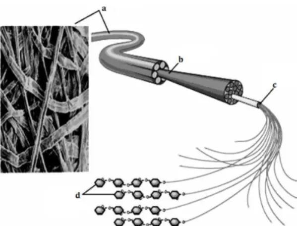
Figure 3 - Cellulose fibrillar structure: a) cellulose fibers, b) macrofibers, c) microfibers, and d) cellulose chains. [6] ... 9
Figure 4 - Cellulose allomorphs Iα(left) and Iβ (right), Carbon ● Oxygen ○ and Hyrdrogen ◦ atoms.[7] ... 9
Figure 5 - SEM image of Gluconacetobacter xylinus bacteria.[2] ... 10
Figure 6 - BC membrane produced in stationary culture (left) and BC pellets produced in agitated culture (right).[2] ... 10
Figure 7- Rotary disk reactor [15] (left); Horizontal lift reactor [4] (right). ... 11
Figure 8 - SEM micrographs of bacterial cellulose surface [25] (left) and cross section [2] (right). ... 12
Figure 9 - Electron micrographs of plant cellulose fibers (left) and bacterial cellulose (right).[26] ... 13
Figure 10 - a) Nata de coco; b) BC artificial blood vessel;[32] c) BC as wound healing membranes.[16] ... 14
Figure 11 - Young modulus (a) and tensile strength (b) of corn starch thermoplastic composites reinforced with 1% and 5% of bacterial and vegetable cellulose.[53] ... 16
Figure 12 - DSC thermograms illustrating the determination of the glass transition and melting temperatures in the nanocomposite (left) and the variation in the melting endotherm of PEO as a function of the BC/PEO w/w ratio (right).[55] ... 17
Figure 13 - Light transmittance of (a) bacterial cellulose pellicle, (b) PLLA/bacterial ... 18
Figure 14 - SEM micrographs of the cross section of BC/PS nanocomposites.[45] ... 19
Figure 15 – Visual aspects of BC/PHEMA/PEGDA (left) and SEM cross sections images (right)[62] .... 20
Figure 16 - Photograph of BC – poly(HEMA-co-EOEMA) composite in the swollen state.[63] ... 21
Figure 17 - Diagram of the various stages of the polymerization reaction.[65] ... 21
Figure 18 - Contact angle of a water droplet over (a) pristine BC, (b) PMMA, and (c) BC-g-PBA.[65] ... 21
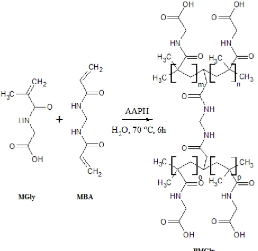
Figure 19 - Schematic representation of the MGly free radical polymerization reaction using MBA as a cross-linker and AAPH as thermal initiator. ... 29
Figure 20 - Visual aspects of a) dry BC, b) dry and c) wet nanocomposite (BC_PMGly 1:3). ... 29
Figure 21 - FTIR-ATR spectra of native BC, PMGly and BC_PMGly nanocomposites with different compositions. ... 31
Figure 22 - Diffractograms of pure BC, PMGly, and BC_PMGly nanocomposites. ... 32
Figure 23 - SEM surface and cross-section micrographs of BC (left), BC_PMGly (1:1) (middle) and BC_PMGly (1:3) (right). Surface images are on the first two rows with magnifications of x10k and x30k and cross-section images are on the last two rows with magnifications of x3.50k and x15k. ... 33
Figure 24 - Thermograms and the corresponding derivatives of BC, PMGly, and BC_PMGly nanocomposites. ... 35
Figure 25 - Storage modulus and tan δ in function of the temperature of BC and BC nanocomposites obtained by DMA analysis in tension mode. The tan δ curves were smoothed with Origin. ... 36
Figure 26 - Tensile stress, Young’s modulus and elongation at break comparison in function of the sample. a) Comparison between BC and the nanocomposites, b) Comparison only between the
nanocomposites. ... 37 Figure 27 - Swelling ratios of BC, and BC_PMGly nanocomposites; Logarithmic fitting was applied with Excel. ... 38 Figure 28 - FTIR spectra of the BC_PMGly 1:3 nanocomposite before and after the swelling tests. ... 38 Figure 29 - Preparation of the extract, 6 cm² membranes dissolved in DMEM media. ... 39 Figure 30 - Visual aspects of the a) PMGly extract, and b) (from left to right) BC, BC-PMGly 1:1, BC_PMGly 1:3 extracts. ... 39 Figure 31 - 96 wells plate with the cell and the extract before incubation. ... 40 Figure 32 - 96 wells plate after 24 hours incubation and 4 hours incubation with MTT ... 40 Figure 33 – Effects of BC, BC_PMGly 1:1, 1:3 and PMGly on the HaCaT cells for exposure time of 24h, 48h and 72h. The results are presented as mean +/- standard deviation from 4 different specimens per membrane. Symbol * represents significant difference between time of exposure for the same membrane (p<0.05). Different letters represent significant differences between one membrane and the control, or one membrane and another membrane for each exposure time (p<0.05). ... 41 Figure 34 - Diclofenac chemical structure. ... 42 Figure 35 - Visual aspect of the dried BC_PMGly1:3_DCF membrane after the impregnation of the drug. ... 42 Figure 36 - FTIR-ATR spectra of BC, PMGly, DCF and BC_PMGly1:3_DCF. ... 43 Figure 37 - Comparison of the absorbance evolution in function of time at pH 7.4 and 2.1 for the BC _PMGly (1:3)_DCF and BC_PMGly (1:3:10)_DCF nanocomposites; fitting was computed with Excel. 44 Figure 38 - FTIR-ATR spectra of BC and BC_PMGly1:3_DCF before and after release test at different pH (7.4 and 2.1) with different amount of cross linker (5% and 10%) ... 45 Figure 39 - XRD diffractograms of the different biomineralized nanocomposites. ... 47 Figure 40 - SEM pictures of a) BC-PMGly 1-2_FDFD, b) BC_PMGly 1:2_FDOD, c) BC_PMGly 1:2_WFD, d) BC_PMGly 1:2 WOD at a magnification of x10k ... 48 Figure 41 - SEM pictures of a) BC-PMGly 1-2_FDFD, b) BC_PMGly 1:2_FDOD, c) BC_PMGly 1:2_WFD, d) BC_PMGly 1:2 WOD at a magnification of x30k ... 48 Figure 42 – Typical EDX spectrum obtained with the BC-PMGly 1:2_FDFD nanocomposite ... 49
List of Tables
Table 1- Comparison of bacterial and plant cellulose fibers properties. ... 13 Table 2: List of the prepared membranes with their compositions ... 23 Table 3: Nanocomposites’ designation and compositions prepared for drug release ... 23 Table 4: Effective Polymer/BC ratio, polymerization yield, and thickness of the different nanocomposites. The thickness was average from 4 different samples per membranes. ... 29 Table 5 : Schematic representation of the plate ... 40 Table 6: Designation of the different biomineralized samples ... 46 Table 7: List of the different elements and their concentrations found in the nanocomposites, the
concentrations are given in wt%. The 2 main compounds (besides carbon and oxygen) of the samples are highlighted in grey. ... 49
List of Abbreviations
AAPH 2,2′-Azobis(2-methylpropionamidine) dihydrochloride AIBN Azodiisobutyronitrile
ATRP Atom transfer radical polymerization BC Bacterial cellulose
BC_PMGly Bacterial cellulose _ Poly(N-methacryloyl glycine) nanocomposite BiBBR 2-Bromoisobutyryl bromide
BM Biomineralization
DBSA Dodecylbenzenylsulfonic acid DCF Diclofenac
DMA Dynamical Mechanical Analysis DMEM Dulbecco′s Modified Eagle′s Medium DMSO Dimethyl sulfoxide
DP Degree of polymerization
FTIR-ATR Fourier transform infrared spectroscopy - Attenuated total reflection
Gly Glycine
HAp Hydroxyapatite
HS Hestrin- Schramm medium MBA N,N'-Methylenebisacrylamide
MC Methacryloyl chloride MGly N-methacryloyl glycine
MTT 3-(4, 5-Dimethylthiazolyl-2)-2, 5-diphenyltetrazolium bromide or thiozolyl blue tetrazolium bromide
NMR Nuclear magnetic resonance PBA Poly(n-butyl acrylate) PBS Phosphate buffer solution PCL Poly(caprolactone) PEG Poly(ethylene glycol)
PEGDA Poly(ethylene glycol) diacrylate PEH Poly(2-ethylhexyl acrylate) PEO Poly(ethylene oxide)
PEOEMA Poly(2-ethoxyethyl methacrylate) PET Poly(ethylene terephthalate) PHEMA Poly(2-hydroxyethyl methacrylate) PLA Poly(L-lactic acid)
PMGly Poly(N-methacryloyl glycine) PMMA Poly(methylmetacrylate) PNVP Poly(N-vinyl pyrrolidone) PVA Poly(vinyl alcohol)
RAFT Reversible addition-fragmentation chain transfer SBF Simulated body solution
SEM Scanning electron microscopy TGA Thermogravimetric analysis TPS Thermoplastic starch
1. The context
At the time where high interest is devoted to the development of new technologies and materials in order to improve life quality, novel high performance health care products are one of the most important focus of scientists. Specifically, advanced medical textiles and devices are topics of large interest and fast development due to their importance in different fields such as wound healing, implantable medical devices, bandaging, surgery, controlled drug delivery, etc. On the other hand, increasing attention and huge efforts have been dedicated to the creation of new environmentally friendly and sustainable materials.
In this context, the present thesis will focus on the development and the characterization of novel bacterial cellulose (BC) based nanocomposites prepared by the in situ free radical polymerization of adequate monomers for potential application in the biomedical field, for example as drug delivery systems or for bone tissue engineering.
Several studies have shown the potentiality to prepare innovative bio-based nanocomposites with distinct properties by combining bacterial cellulose with different natural or synthetic polymers using diverse methodologies. Indeed, BC is known for its peculiar 3D structure that confers to it high mechanical properties and high water retention ability and is also used in several medical fields due to its non-cytotoxicity and biodegradability. Additionally, the selection of the polymer and the corresponding methodology used to perform the polymerization strongly influence the final properties of the nanocomposites. In this study, the aim is to create a new bacterial cellulose based nanocomposite by combination with an acrylate polymer with amino-acid like moieties, namely poly(N-methacryloyl glycine), by means of in
situ free radical polymerization of N-methacryloyl glycine. This new material is expected to
present improved mechanical properties and biological activity as biocompatibility. In a final instance, the objective of this work is to use this novel nanocomposite for biomedical applications such as for instance drug delivery, or for bone tissue engineering, therefore the possibility to induce biological activity to the BC membranes is very pertinent.
The present manuscript will be divided into four main parts. An introduction, describing BC’s production, properties and main applications, followed by a brief review of BC /polymer nanocomposites, with particular emphasis on nanocomposites prepared by in situ polymerization approaches. The second part will described the material and methods involved in the synthesis and characterisation of the new nanocomposites, as well as in the assessment of the future potential applications of the nanocomposites. It will, finally, be followed by a chapter describing the obtained results and the main conclusions of the work.
2. Introduction
Cellulose is the most abundant biopolymer on earth and was discovered in 1838 by Anselm Payen. This biopolymer is the main component of plant cell walls but it can be also produced by several other organisms, including algae, plankton and bacteria.[1] It can be also produced through enzymatic and chemical methods.[2]
From a chemical point of view, cellulose is a polysaccharide composed of glucose units linked by β(1-4) glycosidic bonds.[3] It is this type of chemical bonding that confers to cellulose its linear structure. The repeating unit of a cellulose chain is represented in Figure 1.
Figure 1 - Cellulose repeating unit.
Plant cellulose is typically associated with other plant cell wall constituents, such as hemicelluloses, pectins and lignin, and is characterized by a fibrillar structure, composed of crystalline and amorphous regions, resulting from the high tendency of cellulose chains to establish intra- and intermolecular hydrogen bonds (Figure 2) that promote their aggregation. Those hydrogen bonds are also responsible for the high mechanical strength, high crystallinity degree of cellulose [4] and insolubility in most common solvents.
Figure 2 - Cellulose chains with the hydrogen bondings. [4]
As shown in the Figure 3, cellulose fibers are composed of macrofibers, themselves composed of bundles of microfibers; that are aggregates of several cellulose chains. Plant cellulose macrofibers can vary from 5 to 30 μm in diameter and approximately from 1 to 25 mm in length. For instance, cotton stalks have a length of 0.83 mm and a diameter of 19.6 μm. [5]
Figure 3 - Cellulose fibrillar structure: a) cellulose fibers, b) macrofibers, c) microfibers, and d) cellulose chains. [6]
The crystalline structure of cellulose is quite complex because cellulose can exist in different polymorphs, specifically cellulose I, II, III and IV. Native cellulose commonly presents the cellulose I crystalline structure.[4] Moreover, due to some variations on the hydrogen bonding between cellulose chains, different cellulose allomorphs can be observed. For example, cellulose I has two allomorphs named Iα and Iβ as represented in Figure 4.
Figure 4 - Cellulose allomorphs Iα(left) and Iβ (right), Carbon ● Oxygen ○ and Hyrdrogen ◦ atoms.[7]
The degree of polymerization (DP) of cellulose varies in function of its sources, biosynthesis process and purification or modification treatments. Typically, native cellulose DP is between 3000 and 15000: wood cellulose has a DP of about 10000 and cotton cellulose, the most pure form of cellulose, of 15000. Purification treatments normally induce a reduction of the degree of polymerization.[8]
This quite complex structure confers to cellulose properties such as hydrophilicity, biodegradability, stiffness, and the ability to be chemically modified. [9]
2.1 Bacterial cellulose
Bacterial cellulose (BC) was first identified in 1886 by A. J. Brown. It is produced by bacteria in two main steps, namely the synthesis of uridine diphosphoglucose, and then its polymerization into β-1-4-glucan chains.[10]
Among the bacteria capable of producing BC, the gram negative Gluconacetobacter xylinus (previously known as Acetobacter xylinum) is recognized as the most effective producer. G.
xylinus (Figure 5) is a non-pathogenic, rod-shaped bacterium that produces cellulose from
several carbon and nitrogen sources.[3]
Figure 5 - SEM image of Gluconacetobacter xylinus bacteria.[2]
2.1.1 Bacterial cellulose production
BC can be produced in both static and agitated cultures. In stationary cultures, BC is obtained as an accumulation of a gelatinous membrane on the interface between the air and the culture medium[11] (Figure 6, left), whereas in agitated cultures, it is synthesized in a deep medium in the form of fibrous suspensions, pellets or irregular masses (Figure 6, right). [12]
Figure 6 - BC membrane produced in stationary culture (left) and BC pellets produced in agitated culture (right).[2]
Bacterial cellulose made from agitated and static cultures presents a similar network structure; however, BC produced in agitated culture shows a lower degree of polymerization, crystallinity index and Young's modulus.[13] It has been also shown [14] that BC prepared in agitated conditions is characterized by a lower Iα mass fraction than cellulose produced statically. A
decrease of the cellulose fibrils size has also been observed in agitated culture when compared to static counterpart.
Static cultivation allows the control of the shape and size of the BC pellicles and also permits to obtain homogeneous membranes.[2] These properties are very well appreciated in the biomedical field for instance. However, static cultivations are shaded by high production costs. In order to overcome this limitation and improve the productions yields, some reactors have been developed. For instance, the horizontal lift reactor [15] and the rotator disk [16] (Figure 7) allow a semi-continuous cultivation of BC. The first one give the same properties as statically produced BC whereas the rotating one produce a BC capable to retain two times more water than BC produced in static conditions. Another reactor called "aerosol bioreactor" [17] can be used in order to produce BC in continuous conditions. The production is ensured by a spray of glucose at the interface between the culture medium and the air. It leads to homogeneous pellicles with enhanced mechanical properties. Creation of several sheets of BC instead of one thick membrane is also possible by alternatively stop and start the flux of glucose.
Figure 7- Rotary disk reactor [15] (left); Horizontal lift reactor [4] (right).
Agitating culture reactors have also been developed, they allow BC production with higher production rates, lower costs and different shapes such as elliptical (air lift modified reactor [18]) and spherical (bubble column reactor [2]). For instance, the air lift modified reactors allow producing BC with a three time higher rate and the pellets had an average diameter of 10 mm. It has been considered that these agitating reactors could be the most suitable for large scale BC production.[2]
Another way to improve the BC production is to choose an appropriate culture medium. The most influent parameters of a BC culture medium are the carbon and nitrogen sources. BC is
mostly produced using the Hestrin-Schramm (HS) medium that uses glucose as carbon source and a combination of peptone and yeast extract as nitrogen sources. [19]
However, it has been observed that it is possible to enhance BC production by modifying this culture medium. Several types of carbon and nitrogen sources have been compared. Among the tested carbon sources, one can find several sugars such as glucose, sucrose, maltose, xylose, fructose, lactose, and polysaccharides as starch, but also other compounds such as ethanol and glycerol. Glycerol and glucose were the most efficient sources.[20] In the same study, several nitrogen sources such as peptone, yeast extract, tryptone, and polypeptone beef extract had also been compared, in that case yeast extract was the source leading to the higher BC production.
2.1.2 Bacterial cellulose properties
First of all, bacterial cellulose has a high degree of polymerization (from 2000 to 8000) [21] and a high crystallinity (generally between 60% and 90%).[21] BC is also well known and appreciated for its high purity, because in contrary to plant cellulose, BC is free of hemicelluloses, pectin and lignin. Furthermore, both plant cellulose and bacterial cellulose are biocompatible and biodegradable.[2]
Secondly, bacterial cellulose is characterized by a particular nano fibrillar network structure which confers to it high porosity and water retain capacity.[2] These properties are very useful in wound dressing or burn curing for instance.[22], [23] Specifically, BC nanofibers are approximately 3-15 nm thick and 70-80 nm width. Those nanofibers are composed of protofibers of 2-4 nm diameter gathered to create a ribbon.[2] BC ribbons are arranged in a particular 3D network (Figure 8) which is responsible for BC properties. [2], [24]
Figure 8 - SEM micrographs of bacterial cellulose surface [25] (left) and cross section [2] (right).
This peculiar nano fibrillar structure together with the high crystallinity provides also very good mechanical properties, especially in tension mode. Indeed, the Young's modulus of BC has been reported [2] to beequal to 15 GPa, which is very high compared to other typical polymers widely used in commercial applications, such as polypropylene (PP) or poly(ethylene
terephthalate) (PET). Moreover, BC shows a tensile strength between 200-300 MPa, also considerably high when compared to other polymers and in the same range as steel. These tensile properties make BC very promising as reinforcing element to improve the mechanical resistance of composite materials.
In summary, BC and plant cellulose fibers have the same chemical structure but different morphologies and fiber dimensions (Figure 9), and therefore, completely distinct properties, as summarized and compared in the Table 1.
Figure 9 - Electron micrographs of plant cellulose fibers (left) and bacterial cellulose (right).[26]
Table 1- Comparison of bacterial and plant cellulose fibers properties. Degree of
polymerization Nanofibers dimensions Tensile strength Young's modulus
BC [2] 2000-8000
3-15 nm thickness 70-80 nm width
1-20 μm length
200-300 MPa 15 GPa
Plant cellulose 3000-15000 [21] 5-30 μm diameter [5] 1-25 mm length [5]
300-500MPa
2.2 Bacterial cellulose applications
BC peculiar properties have led to various applications in distinct fields, including for example the food industry, cosmetics and biomedicine.
BC is appreciated for its peculiar viscosity and gelatinous aspects. Indeed, BC is the main component of the Philippian’s dessert "Nata de Coco" [28] (Figure 10). BC has also been used as a food additive in order to modify the texture of the food or to reduce its caloric content.[1], [29]
In the cosmetic industry, BC is used as a component of several commercial products such as, for instance, facial scrubs [30] and masks.[31]
Nevertheless, it is in the biomedical field that BC found most potentialities. For example, BC's high mechanical strength coupled with its biocompatibility, in situ moldability and water retention capacity inspired the production of artificial BC blood vessels [1], [32] (Figure 10). The high mechanical strength allows those vessels to resist to the high blood pressure.
Additionally, BC has also been explored in the field of tissue engineering and in particular for wound and burn treatment (Figure 10).[22] Indeed, its capacity to retain water is really appreciated in order to repair the skin after a burn. BC is able to keep the moisture close to the wound and also to protect it from the air, facilitating the skin regeneration.
Last but not least, BC has been investigated as a drug delivery system,[3], [33]–[40] in particular for transdermal applications. It has been studied in drug delivery system mostly for its porous structure, mechanical properties and its biocompatibility. For example, the use of BC membranes for transdermal delivery of several drugs, as lidocaine, ibuprofen, caffeine and diclofenac have been reported.
Figure 10 - a) Nata de coco; b) BC artificial blood vessel;[32] c) BC as wound healing membranes.[16]
2.3 BC/polymer nanocomposites
The potentialities of BC can be extended by combining it with other materials including natural or synthetic polymers or even inorganic nanophases (for example, BC/silver nanoparticles [23], [41], [42], BC/hydroxyapatite [25], [43]–[46], BC/Fe3O4 [47], BC/Silica [48]). Regarding the
nanocomposites made with polymers, BC has for instance, been extensively used as reinforcing element in nanocomposites for potential applications in numerous fields as electronics and biomedicine areas.[3], [9], [49]–[51] There are at least four distinct ways to prepare BC based nanocomposites: namely (a) blending BC with the polymeric matrix either by melting-mixing or dispersion of BC into the polymer solution followed by drying [52], [53]; (b) modification of the bacteria culture medium (addition of the polymer into the culture medium) [54]–[56]; (c) incorporation of a polymer solution into BC membranes by diffusion followed by drying [57]– [60] and, (d) in situ polymerization inside the BC network.[45], [61]–[65]
In this study, particular attention will be given to BC nanocomposites prepared by in situ polymerization. However, some current researches made with each of the above mentioned methodologies will be also presented in the next section.
2.3.1 BC nanocomposites prepared by blending
Preparing a BC nanocomposite by blending typically involves the previous disintegration and/or modification of the BC membrane followed by mixing with the chosen polymeric matrix. The blending step can be made either by melting mixing, or by dispersion of BC nanofibrils in a polymer solution followed by solvent casting or other drying methodology, as supercritical CO2
drying.
Several types of nanocomposites prepared by blending were studied among which one can for example find, BC/poly(L-lactic acid),[52] and BC/thermoplastic starch(TPS)[53];
For example, BC/thermoplastic starch [53] nanocomposites were made using shredded bacterial cellulose. BC nanofibers were included into the TPS matrix during the gelatinization process of the polymer. As a result, good adhesion between BC and TPS was observed, as well as a good dispersion of the fibers into the matrix. Moreover, an enhancement of the thermal properties, tensile strength and Young's modulus of the polymer were promoted by the addition of BC (Figure 11). However, even if the moisture sorption was reduced by BC, the obtained composites appeared to be humidity sensitive.
Figure 11 - Young modulus (a) and tensile strength (b) of corn starch thermoplastic composites reinforced with 1% and 5% of bacterial and vegetable cellulose.[53]
Another example of BC nanocomposites made by blending are the BC/poly(L-lactic acid) (PLA) that were produced by Yuan and co-workers.[52] These composites were made by thermal-induced liquid-solid phase separation technology in order to reinforce PLA with BC fibers. As a result, the obtained composite had better surface hydrophilicity and thermal properties than PLA, and enhanced porosity and mechanical properties compared to that of the homopolymer.
2.3.2 BC nanocomposites made by modifying the culture medium
The modification of the BC culture medium to produce novel nanocomposites is normally achieved by the addition of either soluble or insoluble polymers to the culture medium before the inoculation. Therefore, the polymer is incorporated into the BC network during the biosynthesis. Normally, this modification of the culture medium doesn't require a special processing after BC production; however, typical purification treatments need to be performed. Culture modification has been used, for example, to synthesize BC nanocomposites with chitin nanocrystals,[54], poly(ethylene oxide) (PEO),[55] and poly(vinyl alcohol) (PVA).[56]
For instance, BC/poly(ethylene oxide) nanocomposites were prepared by adding PEO in the culture medium.[55] Different BC/PEO w/w ratios were tested (from 15:85 to 59:41) and it has been observed that the higher the ratio the smaller the cellulose nanofibers were. The cellulose nanofibers were attached in bundles of 75-770 nm wide and the size of the bundles increase with the content of PEO. However, for all tested ratios, the BC nanofibers were homogeneously dispersed in the PEO matrix. The crystallinity and melting temperature of the nanocomposites were reduced when compared to that of PEO; for the ratio 59:41 the crystallinity went from 67% for pure PEO to 21% and the melting temperature of PEO decreased 10 degrees (Figure 12). Results have also shown that the ratio between Iα and Iβ decrease with an increase of the
BC:PEO ratio and that the preferred crystallization form of BC was Iβ. However, PEO thermal
Figure 12 - DSC thermograms illustrating the determination of the glass transition and melting temperatures in the nanocomposite (left) and the variation in the melting endotherm of PEO as a function of the BC/PEO w/w ratio (right).[55]
Another study reported the synthesis of BC/poly(vinyl alcohol) nanocomposites by addition of PVA into the bacteria culture medium.[56] PVA was introduced to the HS medium under stirring and then incubated at 28 °C. The obtained pellicles were then cross-linked with glyoxal. These nanocomposites kept the transparency of PVA, even for the largest amount of BC. However, the presence of the cross-linker induced a yellowish coloration to the films. BC incorporation in the PVA matrix has led to an increase in the crystallinity of the matrix in the nanocomposite; nevertheless, it did not impact its ductility. Finally, the reinforcement of PVA with BC led to nanocomposites with excellent mechanical, thermal and dimensional properties, as well as moisture stability. This enhancement of the nanocomposites properties is mainly due to hydrogen bonding and chemical cross-linking between PVA and BC.
2.3.3 BC nanocomposites prepared by diffusion of a polymer solution into the BC membrane
This methodology consists in introducing a BC membrane into a specific polymer solution allowing the polymer solution to migrate into the membrane by diffusion. Afterwards, the sample is dried to obtain the nanocomposites.
This technique has already been used to synthesized BC/poly(ethylene glycol),[57] BC/poly(3-hydroxybutyrate),[58] and BC/polycaprolactone (PCL) [60] and BC/poly(L-lactic acid) (PLA) [59] nanocomposites, among many others.
For instance, BC/poly(L-lactic acid) (PLA) [59] nanocomposites were prepared by introducing BC membranes into a PLA solution in chloroform. Optical analysis showed that the characteristic transparency of PLA was kept even after the incorporation of BC (Figure 13). In addition, BC/PLA nanocomposites showed higher crystallinity than pure PLA and improved mechanical properties.
Figure 13 - Light transmittance of (a) bacterial cellulose pellicle, (b) PLLA/bacterial cellulose nanocomposite film, and (c) PLLA film.[59]
2.3.4 BC nanocomposites prepared by in situ polymerization
The preparation of BC nanocomposites by in situ polymerization involves the introduction of a monomer (and initiator and/or cross linker) into the BC membrane, and finally the polymerization is subsequently triggered by setting-up appropriated conditions. Different types of polymerization approaches can be used, such as conventional free radical polymerization, atom transfer radical polymerization (ATRP), reversible addition-fragmentation chain transfer (RAFT), among others. For instance, ATRP is a polymerization technique that allows the covalent linkage between the polymer and the cellulose chains, while in conventional free radical polymerization it could be necessary to use a bi-functional monomer to promote the cross linkage of the polymer inside the BC network and consequently prevent its lixiviation during processing or washing.
Several BC nanocomposites had already been prepared by in situ polymerization using different monomers (aniline,[61]styrene,[45] 4-styrene sulfonic acid,[66] acrylate monomers[62]–[65]) and polymerization methodologies.
For example, conducting BC nanocomposites were prepared by conventional polymerization of aniline, in the presence of dodecylbenzenylsulfonic acid (DBSA), into a BC membrane.[61] First, a DBSA/aniline solution in ethanol and water was prepared and then, the BC membranes were introduced in the solution; afterward the polymerization was carried out at 25 °C during 24 h. The obtained nanocomposites membranes were washed with ethanol. FTIR and XRD analysis were performed and confirmed the polymerization of aniline inside the bacterial cellulose network. Moreover, mechanical tests showed that the nanocomposites were more brittle than BC alone. However, the results showed that the nanocomposites were conductive which confirmed the potentialities of BC as scaffold to create conductive materials.
In another study, Peng et al. [45] prepared BC/polystyrene (PS) nanocomposites by adding a BC membrane into a styrene solution with 1 wt% of azodiisobutyronitrile (AIBN) at room temperature during 3 hours. SEM analysis showed that the porous structure of BC was modified by the PS incorporation mainly because it filled the pores of the BC membranes. Additionally, results showed that the nanocomposites were characterized by a lamellar structure (Figure 14) of 300 nm maximum layer thickness and that the mechanical properties of PS were increased by the creation of the nanocomposites. However, no signs of strong interaction between the two compounds (PS and BC) were observed.
Figure 14 - SEM micrographs of the cross section of BC/PS nanocomposites.[45]
In situ polymerization has also been explored to prepare distinct acrylate polymers/BC
nanocomposites.[62]–[65], Acrylate polymers are widely used because they are very well
known by chemists and easy to prepare and to tune due to the high availability of different acrylate monomers.
For example, BC/poly(2-hydroxyethyl methacrylate) (PHEMA) nanocomposites films were prepared by conventional in situ polymerization using poly(ethylene glycol) diacrylate
(PEGDA) as cross-linker.[62] PHEMA appeared to fill the BC membranes in a quite homogeneous way (Figure 15) and an increase of the translucence of the materials was observed. It has been also shown that the cross-linking prevented the dissolution of the polymer during the washing step and consequently, the polymer content in the nanocomposites increased with the amount of PEGDA. It was also observed that the 3D structure of BC was not affected by the polymerization. The thermal stability and mechanical properties of these nanocomposites were enhanced when compared to those of PHEMA due to the excellent compatibility between BC and the PHEMA. Finally, a good swelling ratio of 200-260% was obtained and biocompatibility tests confirmed that these nanocomposite films were non-cytotoxic and allowed the cellular proliferation.
Figure 15 – Visual aspects of BC/PHEMA/PEGDA (left) and SEM cross sections images (right)[62]
In addition, BC/poly(glycerol methacrylate) (PGMMA),[63] BC/poly(2-hydroxyethyl methacrylate) (PHEMA),[63] BC/poly(2-ethoxyethyl methacrylate) (PEOEMA),[63], [64] BC/poly(2-ethylhexyl acrylate) (PEHA),[64] BC/poly(n-vinyl pyrrolidone) (PNVP) [64] hydrogels were prepared by Hobzova et al. [63] and Kramer et al. [64] All hydrogels were prepared by UV radical polymerization in an aqueous medium after introducing the different monomers into the BC membrane. However, for the case of EOEMA and EHA, which are hydrophobic, a solvent exchange reaction from water to 2-propanol and ethanol was performed. Cross-linkers were used in all cases, and results showed that an almost complete filling of the BC membrane by the polymers was attained with the highest concentration of cross-linkers and only partial fiber covering was obtained with lower concentrations. All nanocomposites were characterized by a good dispersion of the polymers within the BC network and cross linkage appeared to reduce swelling capacity of the composites when high concentrations of cross linkers were used. Figure 16 shows the aspect of a swelled composite. Regarding the mechanical properties, it was observed for all hydrogels an improvement of these properties when compared to the neat polymers.
Figure 16 - Photograph of BC – poly(HEMA-co-EOEMA) composite in the swollen state.[63]
Finally, in a different study, BC/poly(methyl methacrylate) (PMMA) and BC/poly(n-butyl acrylate) (PBA) nanocomposites were produced by ATRP.[65] Firstly, BC membranes were functionalized by esterification with 2-bromoisobutyryl bromide (BiBBR) and then methyl methacrylate or n-butyl acrylate were polymerized from the BC macro initiator (Figure 17).
Figure 17 - Diagram of the various stages of the polymerization reaction.[65]
The obtained composites had properties depending on the amount of polymer grafted into the membranes. Specifically, high grafting led to thermal behaviour similar to the corresponding homopolymer while composites with low polymer incorporation had a TGA profile closer to that of BC itself. The grafting of the polymer conferred to the nanocomposites a hydrophobic character (Figure 18), as well as a decrease of the mechanical properties compared to those of BC.
Figure 18 - Contact angle of a water droplet over (a) pristine BC, (b) PMMA, and (c) BC-g-PBA.[65]
3. Materials and methods
3.1 Chemicals
All chemicals were used as received. 2,2′-Azobis(2-methylpropionamidine) dihydrochloride 97% (AAPH), used as radical initiator, and N,N'-methylenebisacrylamide 99% (MBA), used as cross-linker, were purchased from Sigma-Aldrich. N-methacryloyl glycine 95% (MGly) was acquired from Synchem UG & Co. KG (Germany). For the MTT test, the HaCaT cell line was obtained from Cell Lines Services (Eppelheim, Germany). The phosphate buffer solution (PBS) (pH:7.2) and the Dulbecco′s Modified Eagle′s Medium (DMEM), as well as the fetal bovine serum (FBS), L-glutamine, penicillin/streptomycin and fungizone were purchased from Gibco, (Life Technologies, (Carlsbad, CA, USA), dimethylsulfoxide (DMSO) (reagent plus ≥ 95%) and thiozolyl blue tetrazolium bromide (MTT) were supplied by Sigma-Aldrich. All other reagents and solvents were of analytical grade and used as received.
3.2 BC membranes
Bacterial nanocellulose (BC) (three-dimensional network of nano- and micro-fibrils with 10– 200 nm width) in the form of wet membranes was produced in our laboratory using the
Gluconacetobacter sacchari bacterial strain[67]and following established culture procedures. [19] In detail, the pre-inocula were prepared by growing the bacteria at 30 °C, during 48 h, in static conditions, in HS liquid medium. After this period, the flask was vigorously agitated and 5 mL of the culture media was withdrawn and inoculated into a 45 mL liquid production medium in 250 mL Erlenmeyer flasks. BC membranes were then treated three times with a 0.5 M NaOH solution, at 80 ºC, for 30 min and washed with distilled water until its whitening and reaching pH 7.0. [68]
3.3 BC_PMGly nanocomposites
Wet BC 4x4 cm² membranes were weighted and 60% of their water content was removed by hand pressing. They were then placed in balloons purged with nitrogen (N2) at 0 ºC during 1
hour with an aqueous solution of N-methacryloyl glycine, 2,2′-azobis(2-methylpropionamidine) dihydrochloride (radical initiator) and N,N'-methylenebisacrylamide (cross-linker). Finally, the balloons were left at 70 ºC during 6 hours. The membranes were then washed several times with distilled water and leftward in water during one night. Afterwards, they were dried in the oven at 40°C during 12 hours. The list of the different samples prepared, as well as their compositions is presented in Table 2.
Table 2: List of the prepared membranes with their compositions
Sample WMGly/WBC WMBA/WMGly WAAPH/WMGly
BC - - -
BC_PMGly (1:1) 1 5% 1%
BC_PMGly (1:2) 2 5% 1%
BC_PMGly (1:3) 3 5% 1%
BC_PMGly (1:5) 5 5% 1%
3.4 Drug delivery assays
Impregnation of diclofenac (DCF) into a BC_PMGly membrane
Two different membranes of BC_PMGly 1:3 (one with 5% of cross-linker and the other with 10%) were prepared following the procedure explained in the section 3.2 and kept in wet state; in the meantime, a diclofenac solution was prepared by dissolving 80 mg of DCF in 5 mL of water.
After being drained (40%) the membranes were immersed into the diclofenac solution until complete absorption of the solution and dried in the oven at 40 °C following the method used by Silva et al.[37], and Trovatti et al.[35] and then the release of drug was studied. Table 3 summarizes the different membranes that were prepared and their compositions.
Table 3: Nanocomposites’ designation and compositions prepared for drug release
Sample WMGly/WBC WMBA/WMGly WAAPH/WMGly Diclofenac (mg/mL)
BC _PMGly (1:3:5)_DCF 3 5% 1% 20
BC_PMGly (1:3:10)_DCF 3 10% 1% 20
Drug release test
The release of the drug was tested at two different pH values, namely pH 7.4 and 2.1, in order to compare the influence of the pH media on the release profile.
Drug release tests at pH 7.4 were performed with a 0.01 M phosphor buffer solution (pH 7.4). This solution was prepared by dissolving 8.0 g of NaCl, 0.2 g of KCl, 0.24 g of KH2PO4 and
3.63 g Na2HPO4.10H2O in 1 L of distilled water. The BC membrane was then placed in 500 mL
of this solution previously heated at 37 °C. 5 mL aliquots of the solution were removed every hour and the absorbance at 276 nm was assessed in order to control the release of the drug.
Drug release tests at pH 2.1 were performed by immersing the impregnated nanocomposites into an aqueous solution of HCl (pH 2.1) at 37 °C during 24 hours. Again, the release of the drug was controlled by measuring the absorbance of the solution every hour.
3.5 Biomineralization of the nanocomposites
The biomimetic growth of hydroxyapatite was initiated from simulated body fluid solution and adapted from literature data. [25], [44], [46], [69], [70]
To prepare the SBF solution, 6.5456 g of NaCl were dissolved into 960 mL of water, then 2.2682 g of NaHCO3, 0.373 g of KCl and 0.1419 g of Na2PO4 were added to the solution, that
was then heated to 37°C before adding 0.3049 g of MgCl2 x 6H2O, 9 mL of 1M HCl, 0.3675 g
of CaCl2 x 2H2, 0.071 g of Na2SO4 and 6.057 g of (CH2OH)3CNH2. The pH of the solution was
then adjusted to 7.4 with 40mL of 1M HCl. The volume of the solution was then fixed to 1000 mL with distilled water. The solution was kept in the refrigerator. Magnetic stirring was maintained during the entire preparation.
24 hours later, the nanocomposites were immersed into the SBF solution at 37 °C for 7 days. The supersaturation conditions were maintained by refreshing the solution every 24hours. The resulted nanocomposites were then rinsed with water and dried (half of the sample: freeze dried (FD), the other half: oven dried (OD)) before being characterised by SEM and XRD.
3.6 Nanocomposites characterization
All the obtained nanocomposites membranes were characterized in terms of structure (FTIR), crystallinity (XRD), morphology (SEM), thermal stability (TGA), mechanical properties (tensile tests, DMA), swelling behaviour and biological properties (MTT test).
3.6.1 Fourier Transform Infrared spectroscopy (FTIR)
FTIR-ATR spectra were taken with a Perkin-Elmer FT-IR System Spectrum BX spectrophotometer equipped with a single horizontal Golden Gate ATR cell over the range 600– 4000 cm−1at a resolution of 2 cm−1averaged on 32 scans.
3.6.2 X-Ray Diffraction (XRD)
XRD analysis were carried out on a PANalytica Empyrean diffractometer using Cu Kα radiation (λ=1.541Ǻ). Analysis were made in reflection mode from 5° to 50° (2ϴ) with a step of 0.026° and an absolute step rate of 197s.
3.6.3 Scanning Electron Microscopy (SEM)
SEM micrographs of the membranes surface and cross-section were taken with a HR-FESEM SU-70 Hitachi equipment operating at 4kV. All samples were coated with evaporated carbon. Surface micrographs were obtained with magnification of x10000 and x30000 and cross-section micrographs with magnification of x3500 and x15000.
3.6.4 Thermogravimetric Analysis (TGA)
TGA assays were carried out with a SETSYS Setaram TGA analyser equipped with a platinum cell. The samples were heated from 20 ºC to 800 ºC with a constant rate of 10 ºC min-1 under a
nitrogen flow of 10 mL min-1.
3.6.5 Dynamical Mechanical Analysis (DMA)
DMA was performed with a Tritec 2000 DMA (Triton Technologies) operating in tension modes (single strain) at 1 Hz and 0.005 mm displacement. Samples (30 x 5 mm²) were heated from -100 ºC to 170 ºC with a constant heating rate of 2 ºC min-1.
3.6.6 Mechanical tests
50 x 10 mm² specimens were tested in tension with an Instron 5564 equipment. After being dried in the oven, the specimens were put in a desiccator during 48h to assure a homogeneous humidity and then tested at room temperature with a rate of 10 mm min-1 using a 1 kN load cell.
2 membranes were tested for each nanocomposite composition and 3 replicates were analysed for each membrane. Elongation at break (%), tensile strength (MPA), and Young’s modulus (MPA) were computed with the Bluehill 3 software.
3.6.7 Swelling ratio (SR)
The swelling ratios (SR) of the membranes were determined by measuring the weight difference between wet and dry states of the membranes using the following equation: SR (%) = (Ws – Wd)/Wd x 100; where Ws is the weight of the specimen in the swollen state and
Wd its initial weight in the dry state. For the measurements, 10x10 mm² specimens were dried,
and then immersed in distilled water. Weight increase was then regularly registered during 48 hours.
3.6.8 MTT test
MTT (3-(4, 5-dimethylthiazolyl-2)-2, 5-diphenyltetrazolium bromide) test was performed on BC, BC_PMGly 1:1 and BC_PMGly 1:3 in order to assess the cytotoxicity of the membranes. The membranes with a BC:monomer ratio of 1:1 and 1:3 were chosen as they are the two extreme conditions we have.
A MTT test is a colorimetric assay that is used to determine the viability of the cell metabolic activity. In our case, in order to be closer to the one of the aimed applications (transdermal delivery), we have chosen to work with HaCaT skin cells which is a non-tumorigenic immortalized human keratinocyte cell line. [71] For the test, the cells were grown in complete Dulbecco’s modified Eagle’s medium supplemented with 10% fetal bovine serum, 2 mM L-glutamine, 10000 U/mL penicillin/streptomycin and 250 µg/mL fungizone at 37 °C in 5% CO2
humidified atmosphere. Cells were daily observed under an inverted phase-contrast Eclipse TS100 microscope (Nikon, Tokyo, Japan). The tests were performed on the two extreme nanocomposites: BC_PMGly 1:1 and BC_PMGly 1:3, and to have more accurate results, 3 samples per nanocomposites were tested.
Biocompatibility assessment was divided into 3 main steps:
- Preparation of the extract: step during which the membranes are immersed into the chosen media to induce the dissolution of every product /compound that could be toxic into the media; - Exposure/incubation of the cells: the previous extract is added to the cells, the plates are then put in the incubator from 24h to 72h depending on the test conditions.
- Addition of the MTT reagent and the reading of the plates: the MTT reagent is absorbed by the cells, and the ones that are still alive transform the MTT into its insoluble purple formazan derivative. By assessing the difference of absorbance between the “control” wells and the wells with cells and extract, we are then able to estimate to quantity of cells still alive at the end of the test and therefore characterize the cytotoxicity of the samples.
Protocol of the test:
Samples of 6 cm² area were prepared, rinsed with ultra-pure water and then sterilized in ethanol 70% during one hour. After that time, they were rinsed again with sterilized PBS to remove the ethanol, dissolved in 1.5 mL of medium and incubated at 37 ºC, with 5% CO2 for 24 hours to
prepare the extract. Due to the powder state of the polymer, its extract was prepared by dissolving 100 mg of polymer into 4.5 mL of medium and sterilized by filtration with a nanocellulose filter.
In the meantime, three 96 wells plates were prepared with 5x4 wells filled up with 60000 cells/well, 50000 cells/well and 30000 cells/well corresponding to a future incubation time of 24
h, 48 h, and 72 h. The cells were then incubated during 24 h for adhesion. After that time, the extracts obtained from the incubated membranes were removed and 100 μL of it were added to each well. The plates were then incubated for 24 h, 48 h, and 72 h.
At the end of the incubation time, 50 μL of MTT (at a concentration of 1 g L-1) were added in
each well and incubated for 4 h at 37 ºC in 5% CO2 humidified atmosphere. After that, culture
medium was removed and 150 μL of dimethyl sulfoxide (DMSO) were added into the wells and the plate was placed in a shaker for 2 hours with gentle mixing. Three more wells were filled up with DMSO to perform the blank absorbance measurement. The plates were finally read with a BioTek Synergy HT plate reader. The absorbance of the wells was measured at 570, 551 and 842 nm and analysed with Gen5.1 software. Data were analyzed by a two way ANOVA, followed by a Holm-Sidak test to evaluate the significant differences between the different membranes.
4. Results and Discussion
Different BC nanocomposites membranes were prepared by varying the amount of monomer impregnated into the BC membranes in order to determine the influence of the polymer content onto the nanocomposites properties. Furthermore, because of the different analyses requirements, membranes were also prepared with different sizes and shapes, either 4x4 cm² square or 7 cm diameter disc. However, due to the impossibility to perform a film from the poly(N-methacryloyl glycine), several analysis such as the tensile test and DMA were not performed on the polymer alone.
The schematic representation of the reaction involved during the free radical polymerization is displayed in Figure 19 and the visual aspect of the obtained nanocomposites membranes, in the dry and wet states, and of BC is shown in Figure 20.
One can see that BC, in the dry state, has the appearance of a white film, contrary to the dried nanocomposites that appeared as yellowish films. This first change of visual aspect allowed us to confirm the polymerization of the N-methacryloyl glycine into the membranes. Additionally, the membranes with a BC/monomer ratio of 1:1, 1:2 and 1:3 were quite flexible. However, due to a too high amount of polymer and cross linker, the one 1:5 membrane was very brittle and therefore, the detailed characterization analyses were not performed for this membrane. On the other hand, the wet membranes have the aspect of white swollen gels with good malleability. By analysing the visual aspect of the membrane, homogeneity differences could also been perceived; indeed, square membranes seemed to be more homogeneous than the disc ones. This difference might be due to a better repartition of the monomer into the membranes and a more perfect distribution of both membranes’ surfaces in the case of a smaller sample thanks to a better fitting into the reaction balloon. Moreover, due to the drying step, some irregularities were also observed on the membranes surfaces. In order to improve the homogeneity of the membranes, the circular nanocomposites were then prepared in an Erlenmeyer instead of a balloon, to induce a better symmetry of the membranes’ surfaces into the reaction medium. Finally, the amount of polymer impregnated into the membranes, as well as the yield (conversion rate) of the polymerization reaction were determined by assessing the weight difference before and after the in situ free radical polymerization and are summarized in Table 4. The thickness of the membranes, in dry state, were also measured and correlated with the amount of acrylate polymer introduced into the membranes. The higher the amount of acrylate polymer introduced, the thicker the membranes, nevertheless, one has to keep in mind that this thickness, is also influenced by the initial thickness of the BC membrane.
Figure 19 - Schematic representation of the MGly free radical polymerization reaction using MBA as a cross-linker and AAPH as thermal initiator.
Figure 20 - Visual aspects of a) dry BC, b) dry and c) wet nanocomposite (BC_PMGly 1:3).
Table 4: Effective Polymer/BC ratio, polymerization yield, and thickness of the different nanocomposites. The thickness was average from 4 different samples per membranes.
BC mass, dry state (mg) MGly mass (mg) Nanocomposites mass (mg) BC/PMGly ratio PMGly/MGly (%) Thickness (mm) BC_PMGly 1:1 282.17 282.2 352.71 4.0 25% 0.113 BC_PMGly 1:2 387.00 774.00 511.00 3.1 16% 0.145 BC_PMGly 1:3 390.64 1117.3 619.40 1.7 19% 0.170
4.1 Fourier Transform Infrared spectroscopy (FTIR)
FTIR analysis was performed in order to confirm the success of the MGly polymerization into the BC membranes. Figure 21 displays the FTIR-ATR spectra of pure BC, PMGly and the different BC_PMGly nanocomposites prepared in this study.
On the one hand, the main bands observed in the FTIR spectrum of pure BC are a broad band around 3340 cm-1 corresponding to the O-H vibrations; two small bands around 2893 cm-1
attributed to the stretching vibrations of the CH2 and CH groups; two peaks around 1330 cm-1
and 1105 cm-1, respectively matching the C-H and C-O vibrations of the C-OH groups; and a
sharp band around 980-1050 cm-1 assigned to the stretching vibration of C-O-C of the acetal
linkages of cellulose [66], [72], [73]
On the other hand, the FTIR spectrum of PMGly is characterized by one band at 3342 cm-1
assigned to the amine N-H stretching; another one at 2930 cm-1 due to the O-H vibrations, two
peaks corresponding to the stretching of the C=O moieties at 1715 cm-1 (methacryloyl) and
1621 cm-1 (glycine), and one peak at 1190 cm-1 corresponding to the vibrations of the C-O
coming from the C-OH groups of the glycine moieties.
In addition, while looking at the nanocomposites spectra, one can first observe that they clearly correspond to the sum of BC’s and PMGly’s spectra, which corroborate the success of the polymerization. Hence, the polymerization was confirmed by the appearance of the specific vibrations of PMGly such as: the two bands matching the C=O vibrations at 1715 cm-1 (C=O
methacryloyl) and 1623 cm-1 (C=O glycine); the band at 1519 cm-1 attributed to the NH
deformation; and the one at 1191 cm-1 due to the vibrations of the C-O acrylate ester. The NH
characteristic vibration at 3340 cm-1 can also be observed on the nanocomposites spectra,
however, one can notice that it appears with a decreased intensity compared to the one on the polymer spectrum due to overlap with the OH vibration of bacterial cellulose. The bands at 2894 cm-1 (C-H stretching), 1300-1400 cm-1 (C-OH) and 1160-1190 cm-1 (C-O stretching) are
typical of both BC and PMGly. Finally, the results show that the intensity of the characteristic peaks of the polymer are increasing with the amount of polymer into the nanocomposite.
Figure 21 - FTIR-ATR spectra of native BC, PMGly and BC_PMGly nanocomposites with different compositions.
4.2 X-Ray Diffraction (XRD)
X-ray diffraction analyses were performed on BC and BC nanocomposites to evaluate the effect of the polymerization on the crystallinity of the different membranes. The obtained diffractograms are shown in the Figure 22.
The diffraction pattern of BC, displays the typical reflections of Cellulose I with peaks at 2θ equal to 14.8° (101), 16.8° (101), 22.9° (002) and 36.3° (040). [21], [65], [72]
Conversely, poly(N-methacryloyl glycine) is an amorphous polymer. Indeed, no significant crystalline orientation reflections are observed on its diffractogram. It is characterized by a broad band centered on 18° typical of amorphous polymers.
Regarding the different nanocomposites, one can noticed that they all displayed the same crystalline pattern, with three main reflections coming from BC semi-crystalline structure at 2θ equal to 14.4°, 16.8° and 22.7°; furthermore, the spectra showed a decrease crystallinity compared to BC due to introduction of the amorphous polymer into BC’s network.
Figure 22 - Diffractograms of pure BC, PMGly, and BC_PMGly nanocomposites.
4.3 Scanning Electron Microscopy (SEM)
A selection of SEM micrographs of the surface and cross-section of the different nanocomposites membranes and pure BC are shown in Figure 23. Those SEM analyses were used to additionally confirm the polymerization reaction, to determine the morphology of the nanocomposites and compare the difference in the structure induced by the amount of polymer introduced into each membrane.
The micrographs of pure BC showed the typical 3D network structure of BC revealing randomly organised nanofibers (surface images) and a lamellar structure (cross-section micrographs). [24], [66], [72]
The micrographs of the different nanocomposite membranes allowed to observe not only the inclusion of the acrylate polymer into the BC 3D network but also the polymer formation on
BC’s surface and, therefore, allowed to confirm the success of the polymerization. Moreover, all the nanocomposite membranes clearly showed the typical nano- and microstructure of BC, which permits to affirm that this was not affected by the polymerization reaction (Figure 23). Finally, by the comparison of the different nanocomposites micrographs one can observe that, as expected, the lower the ratio BC/monomer, the higher the amount of polymer included into the BC membranes. Indeed, this is illustrated on the cross-section micrographs, by more filled up lamellar spaces in the case of a ratio 1:3 than 1:1 and on surface micrographs, by an higher covering of the 3D network (membranes 1:3) and a more distinct network in the case of the 1:1 membranes (Figure 23).
Figure 23 - SEM surface and cross-section micrographs of BC (left), BC_PMGly (1:1) (middle) and BC_PMGly (1:3) (right). Surface images are on the first two rows with magnifications of x10k and x30k and cross-section images are on the last two rows with magnifications of x3.50k and x15k.
4.4 Thermogravimetric Analysis (TGA)
Thermogravimetric analysis was used to check the thermal behavior of the nanocomposite membranes and of the corresponding individual components.
The pure BC membrane displayed a thermogram with a single weight loss profile, typical of cellulosic substrates, with an initial decomposition temperature around 270 ºC and a maximum decomposition temperature at 348 ºC, corresponding to a weight loss of 47%.
In comparison, the poly(N-methacryloyl glycine) showed a double step weight loss profile and is less thermally stable than BC. Its first decomposition initiated around 170 ºC and reached its maximum at 242 ºC (weight loss 15 %) and the main decomposition started around 325 ºC with a maximum at 404 ºC and corresponded to a weight loss of 60%.
All the nanocomposites showed a three step weight loss profile displaying decompositions due to both BC and the acrylate polymer. All membranes started to degrade at around 190 ºC and reached their first maximum decomposition between 232-242 ºC. The second degradation step of the membranes corresponded to the decomposition of BC and began at 253 ºC and 264 ºC indicating a diminution of the stability compared to BC. The last observed decomposition step was due to the polymer enriched fraction degradation and started around 365 ºC for all the membranes.
Additionally, one can notice an increase of the weight loss associated to the polymer degradation with the increasing amount of polymer introduced into the membranes.
In sum, with a thermal degradation starting at around 190 ºC instead of 170 ºC for the homopolymer the membranes can be considered more thermally stable than the PMGly itself. This increase in thermal stability can be ascribed to the good compatibility between BC and the polymer and the interactions established between them.
![Figure 6 - BC membrane produced in stationary culture (left) and BC pellets produced in agitated culture (right).[2]](https://thumb-eu.123doks.com/thumbv2/123dok_br/15849472.1085389/16.892.182.708.828.1031/figure-membrane-produced-stationary-culture-pellets-produced-agitated.webp)
![Figure 7- Rotary disk reactor [15] (left); Horizontal lift reactor [4] (right).](https://thumb-eu.123doks.com/thumbv2/123dok_br/15849472.1085389/17.892.185.709.646.851/figure-rotary-disk-reactor-left-horizontal-reactor-right.webp)
![Figure 9 - Electron micrographs of plant cellulose fibers (left) and bacterial cellulose (right).[26]](https://thumb-eu.123doks.com/thumbv2/123dok_br/15849472.1085389/19.892.174.720.364.562/figure-electron-micrographs-plant-cellulose-fibers-bacterial-cellulose.webp)
![Figure 10 - a) Nata de coco; b) BC artificial blood vessel;[32] c) BC as wound healing membranes.[16]](https://thumb-eu.123doks.com/thumbv2/123dok_br/15849472.1085389/20.892.138.761.776.939/figure-nata-artificial-blood-vessel-wound-healing-membranes.webp)
![Figure 11 - Young modulus (a) and tensile strength (b) of corn starch thermoplastic composites reinforced with 1% and 5% of bacterial and vegetable cellulose.[53]](https://thumb-eu.123doks.com/thumbv2/123dok_br/15849472.1085389/22.892.131.768.107.296/figure-strength-thermoplastic-composites-reinforced-bacterial-vegetable-cellulose.webp)
![Figure 12 - DSC thermograms illustrating the determination of the glass transition and melting temperatures in the nanocomposite (left) and the variation in the melting endotherm of PEO as a function of the BC/PEO w/w ratio (right).[55]](https://thumb-eu.123doks.com/thumbv2/123dok_br/15849472.1085389/23.892.179.714.110.304/thermograms-illustrating-determination-transition-temperatures-nanocomposite-variation-endotherm.webp)
![Figure 14 - SEM micrographs of the cross section of BC/PS nanocomposites.[45]](https://thumb-eu.123doks.com/thumbv2/123dok_br/15849472.1085389/25.892.313.582.702.903/figure-sem-micrographs-cross-section-bc-ps-nanocomposites.webp)
![Figure 15 – Visual aspects of BC/PHEMA/PEGDA (left) and SEM cross sections images (right)[62]](https://thumb-eu.123doks.com/thumbv2/123dok_br/15849472.1085389/26.892.167.729.417.621/figure-visual-aspects-phema-pegda-cross-sections-images.webp)