2005 IEEE 6th Workshop OR Signal Processing Advances in Wireless Communications
zyxwvutsrqponmlkjihgfedcbaZYXWVUTSRQPONMLKJIHGFEDCBA
DETECTION OF NON-ORTHOGONAL PAM SIGNALS WITH
zyxwvutsrqponmlkjihgfedcbaZYXWVUTSRQPONMLKJIHGFEDCBA
SPECTRAL
OVERLAPPING
zyxwvutsrqponmlkjihgfedcbaZYXWVUTSRQPONMLKJIHGFEDCBA
A.
M
zyxwvutsrqponmlkjihgfedcbaZYXWVUTSRQPONMLKJIHGFEDCBA
P. de
Lucena('),
J. C.
M
zyxwvutsrqponmlkjihgfedcbaZYXWVUTSRQPONMLKJIHGFEDCBA
Mota(2).
arid
zyxwvutsrqponmlkjihgfedcbaZYXWVUTSRQPONMLKJIHGFEDCBA
C.
C.
Cavalcante'".
( 1 )
zyxwvutsrqponmlkjihgfedcbaZYXWVUTSRQPONMLKJIHGFEDCBA
CRNKEP, National Institut
of
Space
Research, Fortaleza,
CE, Brazil,
macilio@roen.inpe.
br
(2)
GTELDETI, Federal University of Ceari, Fortaleza, CE,
Brazil.
(mota,charles
]
zyxwvutsrqponmlkjihgfedcbaZYXWVUTSRQPONMLKJIHGFEDCBA
@gtel.ufc.br
ABSTRACT
A model for a communication system transmitting two non- orthogonal
n-PAM
signals with spectral overlapping through an AWGN band-limited channel is established. The system isshown to be equivalent to a discrete time-variant multi-user channel with strong interference among users. A receiver structure based on source separation concepts is proposed. The performance of signal detection in terms of symbol error rate is evaluated using Monte Carlo simulations.
.
1. INTRODUCTION
Several communication systems using multiple access strategies, like OFDM [ I ] and CDMA [Z] utilize orthogonal waveform signals to transmit information from different users. The orthogonality among waveforms makes possible spectral superposition of signals that increase the system bandwidth efficiency without power performance degradation.
On the other hand, the modulation system { ~ U - Q A M ) ~ [3]
zyxwvutsrqponmlkjihgfedcbaZYXWVUTSRQPONMLKJIHGFEDCBA
transmits simultaneously two non-orthogonal m-QAM signals
with spectral overlapping but
zyxwvutsrqponmlkjihgfedcbaZYXWVUTSRQPONMLKJIHGFEDCBA
with
no sacrifice in power budget.However, the great limitation of this modulation technique is the channel bandwidth required which must be theoretically infinite
to hold the power efficiency of the system.
In this work, we investigate the situation where DO
orthogonality between waveforms is considered and the channel
is band limited.
This paper presents an original mathematical model and analysis of a communication system that transmits at the same time two band-limited n-PAM signals with partial spectral superposition over AWGN channels. Also, a receiver structure i s proposed based on source separation concepts.
The rest of the paper is organized as follows. In Section 2,
the system i s described, expressions for demodulated signals in the proposed mathematical model are shown, and a discrete-time model to the system is presented. In Section 3, symbol separation and detection strategies are proposed. Monte Carlo simulation results comparing the performance of the proposal
w.r.t. symbol error rate are presented in Section 4. Finally in
Section 5 , ow conclusions and perspectives are stated.
2.
SYSTEM DESCRIPTION
The block diagram of system transmitter is given in the Fig.1.
The signals
xl
(k)
andq
(k)
are the trmsmitted symbols in the instantI;
fiom two independent sources. Symbol duration is T,
and
J;
andf,
are the transmission frequencies of eachn - P A M
signal. We suppose
zyxwvutsrqponmlkjihgfedcbaZYXWVUTSRQPONMLKJIHGFEDCBA
f,
>f;
and Af =f,
-
f;
< in order tohave spectral overlapping between the transmitted signals. The
pulse shaping filter is represented by g ( t )
and
we suppose that the pulse spectrum is a square root raised cosine with roll-off equal to zero.W Y
Acos2TCf;t
cus27tht
Fig.
1-Transmitter block diagram.
The receiver block diagram is shown in Fig. 2. We assume
perfect synchronization at receiver end. The task of low-pass
filters (LPF) at mixer outputs is to eliminate the signal around
2f,, 2f,
and4
+ &
. The filters g ( t ) are matcbsd filters identical to the transmitter filters ones. The channel is assumedAWGN with bandwidth
B
=%,
The noisen(t)
at the receiver input is supposed to be white Gaussianwith
power spectral densityN$
and mean zero.The demodulated and sampled signals
d,(m)
and4 ( m ) ,
as indicated in Fig. 2, are the inputs of a symbol detection
system that delivers the detected signals
.E,
(m)
andi ,
(m)
.The
zyxwvutsrqponmlkjihgfedcbaZYXWVUTSRQPONMLKJIHGFEDCBA
signalzyxwvutsrqponmlkjihgfedcbaZYXWVUTSRQPONMLKJIHGFEDCBA
r ( t ) at the receiver inputzyxwvutsrqponmlkjihgfedcbaZYXWVUTSRQPONMLKJIHGFEDCBA
is
givenby:
zyxwvutsrqponmlkjihgfedcbaZYXWVUTSRQPONMLKJIHGFEDCBA
The signals
zyxwvutsrqponmlkjihgfedcbaZYXWVUTSRQPONMLKJIHGFEDCBA
4(t)
and& ( t )
at the output of matchedfilter are:
zyxwvutsrqponmlkjihgfedcbaZYXWVUTSRQPONMLKJIHGFEDCBA
d,(t)
zyxwvutsrqponmlkjihgfedcbaZYXWVUTSRQPONMLKJIHGFEDCBA
= -$,(k)g(t -kT)
*
g(b)zyxwvutsrqponmlkjihgfedcbaZYXWVUTSRQPONMLKJIHGFEDCBA
+
t=0
q r . )
= Tz;(t)g(t -kT)
*
g(t) twhere
*
indicates convolution and the noise termsn , ( t )
andn,(t)
can be written asn l ( t )
= [2n(t)cos2qf$]* g(t) (4)%(t)
= [2n(t)cos2nf2i]*
g ( t ) ( 5 )Since g ( t ) is known and the power spectral density is
Ni,
kom Eq. (4) and
(S),
we get the following results to noisezyxwvutsrqponmlkjihgfedcbaZYXWVUTSRQPONMLKJIHGFEDCBA
termsvariance [4]:
E{[n,(t)l’}
=
E{[n,(t)l’)
=No
(6)In this work, it was considered that there is no correlation
between
% ( t )
and
% ( t ) meaning
the worse case condition. Applying Fourier transform in (2)and
(3) and doing somemathematical manipulations we get the expressions for discrete
time signals
d,
( m ) andd,
( m )
:d,(m) = r,(m)t(l-TAf)~sinc[(l-T‘Aj)(m-k)]~
k=O (7)
.
C O S [ K T A ~ ( V I I- k ) ] z 2 ( k )+
T L , ( ~ ) ,Knowing that function sinc[(l -
AfT) ( m
-
k)]
has amaximum
at m=
k
and
decreases whenIm
-
kl
increases,we
can consider as significant term
zyxwvutsrqponmlkjihgfedcbaZYXWVUTSRQPONMLKJIHGFEDCBA
in
summationin
Ek+ (7)and
(8)ody
2 L
+
1
samples centered in the instant mwhere
L
is a
given integer. The original summations
with infinite terms
IC
= O,-..,m,--.,m isreplaced by the additions of 2 L + 1
termswith k=O,...,m,..-,m+ L.Forexample,if
L = 5
is used
in
the case where TAj
=
g,
the
power reduction
of summation
is less than
0.2
dB.
Supposing causal filters, and changing
the
reference
time
in
such
a
way
that the most advanced received
symbol inside
thedemodulated signals
is
at the present
instant
m,
we
canrewrite
t h eexpressions for
4 ( m )
and
d,
( m )in
thefollowing form:
4 ( m )
= z1(m -L)
t(1
-
TAf){
2 L
x s i n c [(l -
TAj)(j
-
L)]COS
[nTAj(2m
+
L
-
j ) ]@
}
(9)
Notice that the demodulated signals contain the desired
symbol plus Gaussian noise and several (2L
+
1) interferenceterm originated
from
another
user.
In
Edct, theinterfering signal
is equivalent to the output of a linear time variant
FIR
filter thathas
the second user symbol as its input.The
Figure 3 shows an equivalent model that representsthe system since the transmission up to the demodulation.
rz,(m-L)
:++-+-
d,(m)
iz,(m-L)
1;
I
-_.
Fig.3- Equivalent
Model.The linear filters
h:,
zyxwvutsrqponmlkjihgfedcbaZYXWVUTSRQPONMLKJIHGFEDCBA
:
h
Ihl”,
andhl
can be written invectorial form as follows:
h:=h,",=[h,(m)
zyxwvutsrqponmlkjihgfedcbaZYXWVUTSRQPONMLKJIHGFEDCBA
-8.zyxwvutsrqponmlkjihgfedcbaZYXWVUTSRQPONMLKJIHGFEDCBA
h,(m)
zyxwvutsrqponmlkjihgfedcbaZYXWVUTSRQPONMLKJIHGFEDCBA
- + *h L ( m ) ]
(12)zyxwvutsrqponmlkjihgfedcbaZYXWVUTSRQPONMLKJIHGFEDCBA
where
h, ( m ) =
zyxwvutsrqponmlkjihgfedcbaZYXWVUTSRQPONMLKJIHGFEDCBA
(1-
T A f )sine[(
1 - TAf)
( jzyxwvutsrqponmlkjihgfedcbaZYXWVUTSRQPONMLKJIHGFEDCBA
-
L ) ]
cos R TAj ( 2 m+
L
- j )and j = 0:..,2L.
The problem after
zyxwvutsrqponmlkjihgfedcbaZYXWVUTSRQPONMLKJIHGFEDCBA
this point is how to detect thetransmitted sequences { x , } and
zyxwvutsrqponmlkjihgfedcbaZYXWVUTSRQPONMLKJIHGFEDCBA
{x2] fiom the demodulatedsignals
d,
(m)
and4
(m)
.
This is thezyxwvutsrqponmlkjihgfedcbaZYXWVUTSRQPONMLKJIHGFEDCBA
issue of next section.3.
SYMBOL DETECTION
If the symbol detection is performed directly fiom demodulated
signals
4(m)
andd,(m),
withoutany
interference cancellation, the symbol error rate would be very high, as shownby simulation results presented in next section. Then, it is necessary to introduce some interference cancellation in the receiver scheme. Notice although the filter
hyi, hli,
h:
andhg
in the model are time variant fiIters, they are knownand
are given by Eq. (11) and (12).In
this work we consider two schemes where interference cancellation is performed first thansignal detection. We describe tbese schemes in the sequel.
3.1.
Detection scheme
It is evident that each demodulated signal can be thought like a
mixture between a desired signal from
a
given source and asecond interfering signal fiom another source convolved with a
linear time variant F~R(TVFIR) filter. Source separation for a very similar situation, except the assumption the filters are time invariant, is discussed in the literature [S]-[6].
If we process the demodulated signals d, (m) and
d2
(m)
with the two input and two output scheme illustrated by Figure
4, it is straightforward verifying that we have the signals
separation when the following conditions are satisfied:
zyxwvutsrqponmlkjihgfedcbaZYXWVUTSRQPONMLKJIHGFEDCBA
<
$
&
-
b
Equalwr Y* (111)4
(4
VZ (111)Fig.4-
Source
separation scheme.
Supposing L=l,
with
no loss of generality, and using the Eq. (13)-(14), the separated signals v,(m) and vz(m) are:Notice by Eqs. (15) and (16), that the separated signals are
not suitabk yet to detection. This is due the fact that symbols present in the signals are dispersed in time, resulting in intersymbal interference
(1SJ).
It worth noting that the coefficients multiplying the transmitted symbols are time dependent. This situation is similar to the transmission of symbol sequences through a linear time variant filter which coefficientsare represented by
implies that we
need
to equalizevl(m)
andv2(m)
before detection.The equalization can be performed using a linear time
variant FLR filter. The equalizer tap weigbt coefficients ( ~ ~ ( 1 1 1 ) )
for
a
given instaatm
,
as shown by Fig. 4, may be given as the solution that minimize the mean square value of the errorc ~ ~ > = t c o ( m l
C l b > c2@>c3(m)
c , ( d
Illise,(n)
= z , ( m - D ) - y , ( m ) ,
i =
1,2,(24)
where x,(m - 0 ) is the desired symbol, D is a given delay and
y,(m) is the output of equalizer. Actually, the above defined criterion, results in a Wiener filtering for each instant m.
For vl(m)equalization, the tap weight coefficients of equalizer, represented by vector w , ( V I )
,
for a given instant mshould be:
wl(m)
=zyxwvutsrqponmlkjihgfedcbaZYXWVUTSRQPONMLKJIHGFEDCBA
E(v,(m)vT(m))-'
zyxwvutsrqponmlkjihgfedcbaZYXWVUTSRQPONMLKJIHGFEDCBA
E{v,(m)zi(m-
D)}
zyxwvutsrqponmlkjihgfedcbaZYXWVUTSRQPONMLKJIHGFEDCBA
zyxwvutsrqponmlkjihgfedcbaZYXWVUTSRQPONMLKJIHGFEDCBA
(25)where
zyxwvutsrqponmlkjihgfedcbaZYXWVUTSRQPONMLKJIHGFEDCBA
v , ( m ) =[v,(m)zyxwvutsrqponmlkjihgfedcbaZYXWVUTSRQPONMLKJIHGFEDCBA
I - .zyxwvutsrqponmlkjihgfedcbaZYXWVUTSRQPONMLKJIHGFEDCBA
~ ( w L - N ) ] ~ andN
is thenumberof coefficients of the equalizer.
DFE equalizer with time variant forward and feedback filters obviously could be also used to perform the equalization.
The
zyxwvutsrqponmlkjihgfedcbaZYXWVUTSRQPONMLKJIHGFEDCBA
MSE
criterion should be used to h d the filters coefficientsfor each instant m. In this case, for vl(m) signal equalization, the forward filter coefficients
f
(m)
is given by the equation:f,,
(m)
=E
{VI( 4 v T
i q l
E
{VIzyxwvutsrqponmlkjihgfedcbaZYXWVUTSRQPONMLKJIHGFEDCBA
(m)q
(m
-
D)}
(26)
where
vI(m>=[v,(m)
-..v , ( m - D ) ] ' ,
q ( m - D ) x , ( m -D) is the desired symbol, and
D
is the decision delay. Thefeedback filter, represented by
f,
(m)
,
is given by:D
"66 =
~ f & 4 % + d ~ -
4,
1 =zyxwvutsrqponmlkjihgfedcbaZYXWVUTSRQPONMLKJIHGFEDCBA
L.-.,M (27)#=O
where c,(m) are given by Eqs. (17)-(21), M is the number of coefficients in the feedback filter and f , (m) are the coefficients
of the feedforward filter.
Then, after equalization the signals 6om both fkquencies
(users) can be detected. However, another strategy may be used
as described in next section.
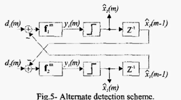
3.2 Alternative
Approach
A DFE-like equalizer
with
time variant feedforward and feedback filters could be also used to perform the detection, asdepicted in Fig. 5 , since we are dealing with an interference removal issue.
From Fq. (9) and (lo), and assuming L=I, we can verify
that the scheme represented in Fig. 5 also detects the
symbols.
Symbols originated by
an
user in demodulated signal are cancelledwith
the feedback of delayed decision. After that the time disperse signal 6 0 m another user that remains is equaliied by a TVFIR filter (fy
orf?
) before the decision. Notice the linear equalizersf;"
andf;
could be replaced also by a DFEequalizer with time variant filter.
2;
imjFig.5- Alternate
detectionscheme.
Ideally, we could obtain the separated'signal yl(m) and Y a ( 4 :
Depending on the value of h,,(m) it should have a noise amplification process and the system performance should be
poor.
It should be necessary to spend more power in thetransmission to keep the performance or use strategies to reduce only the noise power as described in [7]. Applications of such strategies in
this
problem are still being investigated and were not implemented in this work.We have verified during simulations, that this scheme works satisfactorily only in conditions of high signal-to-noise ratio
(SNR).
Despite its poor performance in lowS N R
environments, it remains interesting due to its simpler and flexible structure compared
with
the first one making it more suitable for adaptive processing.Furthermore, the processing with the alternative approach leads to the preservation of an AWGN channel
with
anattenuation of the original signal.
4.
SIMULATION
RESULTS
We have simulated a system with
binary
PAM signals,AjT
=x
,
and
L
= 1.
In this case, the filters for the equivalent model describedin
Fig. 3 are:h;
=hy2 = [ 0
1 03,h;",
= G I= b o b )
h l b > h2",where
t+,(m)= 0 . 2 7 5 7 c o s [ n ( 2 m + l ) / 3 ] ,
h-,(m)
=0 . 6 6 6 7 c o s [ ~ ( 2 m ) / 3 ]
h ( m )
=
0 .2 757 co s[~ ( 2m- l )/ 3]
It worth noting that the filter coefficients
h,
(m)
,
h,
(m)
,
and
h2(m)
although time variant, are periodic with periodP = 3 ,
resulting in only three possible filters. This factsimplifies the implementation of the detection schemes. Fig. 6 shows the symbol error rate
(SER)
at different values of symbol energy by noise density & N o ) for theproposed detection scheme and the altemative one, compared
with
the situation when the detection is done directly &omdemodulated signal without any interference cancellation. For the fist detection scheme, the used equalizer was a DFE equalizer
with
a decision delay equals 2, a time variant feedforward filter with 3 taps and a time variant feedback filter with 4 taps optimized by the MSE criterion.T h e
equalizer of thealtemative scheme is a DFE one with a decision delay equals zero, f e e d f o m d filter
with
1 tap and feedback filterwith
2 taps10‘
zyxwvutsrqponmlkjihgfedcbaZYXWVUTSRQPONMLKJIHGFEDCBA
102
LT
w m
zyxwvutsrqponmlkjihgfedcbaZYXWVUTSRQPONMLKJIHGFEDCBA
\ i
, , ,
zyxwvutsrqponmlkjihgfedcbaZYXWVUTSRQPONMLKJIHGFEDCBA
1
0 2 4 6
zyxwvutsrqponmlkjihgfedcbaZYXWVUTSRQPONMLKJIHGFEDCBA
8 10 12 14 16 18E S f b
i 0“
zyxwvutsrqponmlkjihgfedcbaZYXWVUTSRQPONMLKJIHGFEDCBA
Fig.6- Symbol error rate
The superior performance ‘of the first scheme is evident. The reason for the difference in performance is the cancellation and equalization process in each scheme.
In alternative approach, there is a cross-feedback between usem signals in order to make the principal user canceIIation and
to preserve the terms of interfering user. Then, a
DFE
equalizer with a decision delay equal to zero, eliminates the delayed symbols and maintains the symbols at instant m that aremultiplied by the coefficient
zyxwvutsrqponmlkjihgfedcbaZYXWVUTSRQPONMLKJIHGFEDCBA
h, (m), Eqs. (28) and (29), whichhas low amplitude, resulting in big attenuation. Further, this process amplifies the Gaussian noise and makes the ratio of the signa! to the noise tighter
than
for the first scheme, where the best symbol can be chosen.To cope with this problem, we are studying the impact on
the orthogonality when normalizing
the
channel
to amore
favorable situation.
5.
CONCLUSIONS
AND
zyxwvutsrqponmlkjihgfedcbaZYXWVUTSRQPONMLKJIHGFEDCBA
PERSPECTIVES
We have proposed a mathematical modeling for systems
transmitting non-orthogonal signals with spectral overlapping.
Using the fact that, from the mathematical model, the system can be viewed as a source separation problem, we proposed an interference cancellation scheme for detection of the involved signals.
Simulations have shown that preliminary results fkom the proposed technique to detect two non-olzhogonal n-PAM signals with spectral overlapping for a band-limited channel increases the performance of the system in terms of symbol error rate. The advantage of presented technique (main detection scheme) is low complexity involved even considering the time variant system.
A direct extension o f this work i s the complex modulation.
A generalization of the Viterbi algorithm for multi-user and time variant systems is another technique that is being investigated to be applied in the problem of spectral overlapping.
Further, the consideration of channel estimation is anotber research line to be tracked, since so far we have assumed perfect channel estimation.
6. REFERENCES
[l]
zyxwvutsrqponmlkjihgfedcbaZYXWVUTSRQPONMLKJIHGFEDCBA
S . €3, Weinstein and P. M. Ebert, “Data transmission byhquency division multiplexing using the discrete Fourier
innsfor”’, IEEE Trans. Commun. Techno/. Vol. COM-19, no.
5,pp. 628-634,0Ct.1971.
[2]
R.
L. Pickholtz, D. L. Schilling,L.
B.
Milstein, ‘Theory of Spread-Spectrum Communications-A Tutorial”. IEEE Trans.On
Commun. Vol. COM-30, No. 5 , May 1982.
[3] E. C. Giraudo, F. R. BaIdini and R.
R.
Scarabucci,“On
the(m-QAM)
*
Modulation”. IEEE Communications Let#ers, Vol. 5,no. 10, pp. 426428, Oct. 2001.
[4] Papoulis, A., Probabdity, Random Variables> and
S~ocachastic Process, McGraw-Hill, International Student Edition, 1965.
[SJ
D. Yellin, and E. Weinstein, “MultichanneI Signal Separation: Method and Analysis”, IEEE Trans. on SignalProcessing, VoI. 44, no 1, Jan. 1996.
[6J E. Weinstein. M. Feder, and A. V. Oppenheim, “Multichmel Signal Separation by Decorrelation”, IEEE Trans. on Speech andhdio Proc. Vol. 1 , no 4, Oct. 1993.
[7] J.