Fernando Jorge Varandas Anão Rosado
Licenciado em Ciências da Engenharia Electrotécnica e deComputadores
A Model-driven Architecture for Multi-protocol
OBD Emulator.
Dissertação para obtenção do Grau de
Mestre em Engenharia Electrotécnica e de Computadores
Orientador:
Prof. Doutor Pedro Miguel Maló,
Professor Auxiliar, FCT-UNL
Co-orientador:
Mestre Edgar Miguel Felício Oliveira da Silva,
Investigador, UNINOVA-CTS
Júri:
Presidente: Doutor Tiago Oliveira Machado de Figueiredo Cardoso - FCT/UNL Arguente: Doutor Rui Manuel Leitão Santos Tavares - FCT/UNL
A Model-driven Architecture for Multi-protocol OBD Emulator.
Copyright cFernando Jorge Varandas Anão Rosado, Faculdade de Ciências e Tecnologia,
Universidade Nova de Lisboa
A
CKNOWLEDGEMENTS
Para começar, gostaria de expressar a minha gratidão ao meu orientador Pedro Maló e co-orientador Edgar Silva pela oportunidade de desenvolver esta dissertação sob a sua supervisão. Todo o tempo, apoio e recursos fornecidos foram essenciais para o desenvolvi-mento do trabalho apresentado, mas também para a partilha de conhecidesenvolvi-mentos valiosos.
Aos meus colegas da FCT-UNL e Politechnika Pozna ´nska, pelo espírito de entreajuda e cooperação nas mais diversas situações e pelo convivio proporcionado. Entre eles gostaria de destacar o António Furtado, Cláudio Penedo, Filipe Melo, André Brígida, Miguel Alves, Hugo Frazão, Franscisco Vieira, Nuno de Castro, Mauro Marques, Rúben Anjos, Pedro Sousa, Karim Jalal.
Gostaria também de prestar uma palavra de apreço a toda a minha equipa de natação, CIRL, pelo apoio, perseverança e garra que instruem todos os dias, servindo como escola para as situações do dia a dia. Entre eles não posso deixar de destacar o meu treinador, Alexandre Serrasqueiro, como um exemplo de incansável motivação, dedicação e atitude. Um especial agradecimento à família Pires pelo apoio e preocupação ao longo destes anos.
Aos meus amigos de sempre, também um grande obrigado por acreditarem em mim e estarem sempre do meu lado, tal como todas as outras pessoas que contribuiram para chegar até aqui. Entre eles gostaria de destacar o Manuel Dordio, João Carvalho, Mariana Linhan, Cláudia Marques, Inês Ribeiro, Susana Escária, João Chora, Daniel Lopes (um especial obrigado pela revisão da minha dissertação), João Fialho, João Mósca, Patrícia Magro, Vanessa Magro e fiel Zazu.
Um agradecimento muito especial ao Fernando Brito e Silva por ser um irmão no ver-dadeiro sentido da palavra e à Ana Teresa Maiorgas por todo o apoio incondicional, entreajuda e momentos passados ao longo deste ultimo ano. Obrigado Ana.
A
BSTRACT
The Internet of Things (IoT) might be the next revolutionary technology to mark a genera-tion. It could have a particularly strong influence on the automotive industry, changing people’s perception of what a vehicle can do. By connecting several things in a car, IoT empowers it to sense and communicate. Furthermore, this technology clearly opens the way to emerging applications such as automated driving, to-Vehicle and Vehicle-to-Infrastructure communication.
Vehicle’s information about its environment and surroundings is crucial to the develop-ment of existing and emerging applications. It is already possible to communicate directly (on-site) with vehicles through a built-in On Board Diagnostics (OBD), making it possible to obtain crucial information about the state of the vehicle in real environments. However, there is zero tolerance for error when developing new applications for vehicles that are, a priori, extremely costly and that must also safeguard human lives. Therefore, there is an increasing need for OBD emulators which can allow the development of new applications.
This Thesis proposes a model-driven architecture for multi-protocol OBD emulator, en-couraging the development of new emerging OBD systems in a safety environment, to promote the creation of applications to interact or use vehicles’ data. In this sense, the addressed specifications are: Less expensive comparing with today’s solutions; Compati-ble with different OBD protocols communication; Open Source Hardware and Software suitable for Do-It-Yourself (DIY) development.
R
ESUMO
A Internet das Coisas poderá ser a próxima revolução tecnológica a marcar uma geração. O IoT poderá ter uma influência particularmente forte na indústria automóvel, mudando a percepção das pessoas á cerca do que um veículo pode fazer. Ao ligar várias coisas em um carro, o IoT habilita-o a sentir e comunicar. Além disso, esta tecnologia abre claramente caminho para aplicações em desenvolvimento, como por exemplo: condução autónoma, comunicação veículo-veículo e comunicação veículo-infra-estrutura.
A informação de um veículo acerca do seu ambiente circundante é crucial para o desen-volvimento de aplicações existentes e emergentes. Já é possível comunicar directamente com veículos através de um On Board Diagnostics (OBD), possibilitando assim obter informações importantes relativas ao estado do veículo, em ambientes reais. Contudo, não existe tolerância para erros no que diz respeito a novas aplicações utilizadas em veículos, visto que são a priori dispendiosos e devem salvaguardar vidas humanas. Por conseguinte, existe uma necessidade crescente de emuladores OBD que permitam o desenvolvimento de novas aplicações.
Esta tese propõe uma arquitectura de modelos para emuladores OBD multi-protocolares. Encoraja o desenvolvimento de sistemas OBD emergentes em um ambiente de segurança, de modo a promover a concepção de aplicações para interagir ou usar dados de veículos. Neste sentido, as especificações que foram abordadas são: menos dispendioso quando comparado com as soluções actuais; Compatível com protocolos de comunicação OBD; Hardware e Software em código aberto adequado para desenvolvimento Faça você mesmo (Do-it-Yourself (DIY)).
C
ONTENTS
Contents xiii
List of Figures xv
List of Tables xvii
1 Introduction 1
1.1 Motivation Scenario: OBD - New Emerging Applications . . . 1
1.2 Problem Characterization . . . 3
1.3 Work Methodology . . . 3
1.4 Dissertation Outline . . . 5
2 State-of-the-Art 7 2.1 Review . . . 7
2.2 Individual Review . . . 8
2.2.1 An IoT Gateway Centric Architecture to Provide Novel M2M Services 8 2.2.2 Apache ServiceMix . . . 10
2.2.3 OpenIoT - Open Source cloud solution for the Internet of Things . 12 2.2.4 Universal Device Gateway . . . 14
2.2.5 Synthesis . . . 16
2.3 Main technical approaches . . . 19
2.3.1 JSON . . . 19
2.3.2 Wrappers . . . 19
2.3.3 Model Driven Engineering . . . 20
2.3.4 SaaS - Software as a Service . . . 22
2.4 Remarks . . . 22
2.5 Research Question . . . 23
3 Multiprotocol Architecture for OBD Emulator 25 3.1 Hypothesis . . . 25
3.2 Concept . . . 26
3.3 Architecture Overview . . . 27
3.4 Logical Architecture Specification . . . 28
CONTENTS
3.4.2 Transformation Engine . . . 29
3.4.3 Database . . . 30
3.5 Architecture Composition . . . 31
4 Experimental Setup 33 4.1 On-Board Diagnostics . . . 33
4.2 Supporting Technologies . . . 36
4.2.1 Hardware . . . 36
4.2.2 Software . . . 38
4.3 Experimental Setup Overview . . . 39
5 Implementation and Validation 41 5.1 Controller Area Network . . . 41
5.2 Testing and Validation . . . 44
5.2.1 Data Protocols Meta-Models . . . 46
5.2.2 Arduino to Arduino CAN communication . . . 48
5.2.3 Connect OBD Scanner Module with Arduino . . . 50
5.2.4 Final Demonstrator: Open Source OBD-II Emulator . . . 52
5.3 Summary: Open Source OBD-II Emulator . . . 55
6 Current Solutions 57 6.1 Multiprotocol ECU Simulator - mOByDic4910 . . . 57
6.2 ECUsim 5100 Professional OBD-II ECU Simulator . . . 57
6.3 Freematics OBD-II Emulator MK2 . . . 58
6.4 Comparison . . . 58
7 Conclusions and Future Work 61
Bibliography 63
L
IST OF
F
IGURES
1.1 Overview of the Work Methodology used in this thesis. . . 4
2.1 The proposed IoT Gateway Centric Architecture, based on (Datta et al. 2014). 9 2.2 Apache ServiceMix Architecture, based on (Snyder 2008). . . 11
2.3 OpenIoT Architecture Overview, based on (Soldatos et al. 2015). . . 13
2.4 Universal Device Gateway architecture, based on (Bocchi et al. 2012). . . 15
2.5 An example of a wrapper functionality, based on (GSN Team 2014). . . 20
3.1 OBD Emulator Concept. . . 26
3.2 Communication Enabler Module. . . 27
3.3 Communication Protocols Handler modules. . . 28
3.4 Transformation Engine module. . . 29
3.5 A transformation example between two Data Formats. . . 30
3.6 Architecture Composition. . . 31
4.1 OBD-II connector and respective pinout. . . 34
4.2 Request/Response CAN data frames. . . 36
4.3 The ELM327 Interface Bluetooth version. . . 37
4.4 Front side of Arduino Due. . . 37
4.5 MCP2551 circuit schematic versus MCP2551 real implementation. . . 38
4.6 Experimental Setup Overview. . . 40
5.1 Network with and without CAN, based on (National Instruments 2014). . . . 42
5.2 Can communication electrical levels view, based on (Axiomatic 2006). . . 42
5.3 CAN-Frame in base format with electrical levels (Can Bus - Wikipedia). . . . 43
5.4 Communication Overview. . . 44
5.5 Request Frame. . . 45
5.6 Response Frame. . . 45
5.7 OBD-II Model, based on (OBD-II PIDs - Wikipedia). . . 46
5.8 "Author" Data Protocol Model, based on (OBD-II PIDs - Wikipedia). . . 46
5.9 Arduino to Arduino flowchart (a - Transmitter; b - Receiver). . . 48
5.10 Arduino to Arduino implementation. . . 49
5.11 Arduino to Arduino validation. . . 49
LIST OFFIGURES
5.13 OBD Scanner Module to Arduino implementation. . . 51
5.14 OBD Scanner Module to Arduino validation. . . 51
5.15 ECU Emulator flowchart. . . 52
5.16 Enabler flowchart. . . 53
5.17 Communication Enabler flowchart. . . 54
5.18 Representation of the final implementation. . . 54
5.19 Communication Enabler validation. . . 55
L
IST OF
T
ABLES
2.1 Overview of the State of the Art Research . . . 18
5.1 Meta-Models Mapping, based on (OBD-II PIDs - Wikipedia). . . 47
5.2 Open-Source OBD-II Emulator detailed cost. . . 56
G
LOSSARY
ABS Antilock Braking System4.
ACK Acknowledges.
CAN Controller Area Network.
CEM Communication Enabler Module.
CIM Computation Independent Model.
CPH Communication Protocols Handler.
CPU Central Processing Unit.
CRC Cyclic Redundancy Code.
DF Data Format.
DLC Data Link Connector.
DTC Diagnostic Trouble Codes.
ECM Engine Control Module.
ECU Electronic Control Unit.
EOF End Of Frame.
ESB Enterprise Service Bus.
FTP File Transfer Protocol.
GSM Global System for Mobile Communications.
GSN Global Sensor Networks.
HTTP Hypertext Transfer Protocol.
GLOSSARY
IDE Integrated Development Environment.
IFS Interframe Space.
IoT Internet of Things.
IPsec Internet Protocol Security.
IPv6 Internet Protocol version 6.
ISG Intermediate Sensor Gateway.
ISO International Organization for Standardization.
JAAS Java Authentication and Authorization Service.
JBI Java Business Integration.
JDBC Java Database Connectivity.
JMS Java Message Service.
JSON JavaScript Object Notation.
LSM Linked Stream Middleware.
M2M Machine-to-Machine.
MDA Model Driven Architecture.
MDD Model Driven Development.
MDE Model Driven Engineering.
NMR Normalized Message Router.
OBD On-Board Diagnostics.
ODE Orchestration Director Engine.
OSGi Open Services Gateway initiative.
PCM Powertrain Control Module.
PID Parameter ID.
PIM Platform Independent Model.
PSM Platform Specific Model.
GLOSSARY
RDF Resource Description Format.
REST Representational State Transfer.
RTR Remote Transmission Request.
SaaS Software as a service.
SAE Society of Automotive Engineers.
SMTP Simple Mail Transfer Protocol.
SOA Service Oriented Architecture.
SOAP Simple Object Access Protocol.
SOF Start Of Frame.
SSN Semantic Sensor Networks.
TCM Transmission Control Module.
TCP Transmission Control Protocol.
UDG Universal Device Gateway.
UDP User Datagram Protocol.
WG Wireless Gateway.
WSS Web Services Security.
XML Extensible Markup Language.
XMPP Extensible Messaging and Presence Protocol.
C
H
A
P
T
E
R
1
I
NTRODUCTION
After the World Wide Web and universal mobile accessibility, the Internet of Things (IoT) might represent the biggest technological revolution of our lifetime. The IoT concept refers to the incorporation of several heterogeneous end systems, making them able to commu-nicate among themselves and with users. In this sense, becoming an integral part of the Internet. These interoperable systems find indeed applications in many different domains, such as home and industrial automation, medical aids, intelligent energy management, automotive, traffic management, and many others (Singh et al. 2014).
1.1
Motivation Scenario: OBD - New Emerging Applications
For instance, let us consider the road vehicles used nowadays. Motor vehicles are an essential resource in developed countries; however, car accidents are among the top ten causes of death according to theWorld Health Organization1. A monitoring system which
identifies and reports the status of various vehicle’s subsystems could help prevent road traffic accidents and reduce the response time of emergency services.
As an example, the environment where a car is being monitored and sends all its data to a cloud service. This scenario can be implemented using a microcontroller board connected to the On-Board Diagnostics (OBD), which gives access to live data streams of the vehicle subsystems. This data is processed on a microcontroller and sent, when requested through, for example, an integrated GSM module. A cloud service receives this data and provides it to any smartphone or computer, delivering in real time the diagnosis of the car. The main advantage of this implementation is the capacity to access the car information, with live
1Available at http://www.who.int/mediacentre/factsheets/fs310/en/- last update May
CHAPTER 1. INTRODUCTION
stream data, which can prevent accidents and transmit a distress signal in case of theft. Another important advantage is to reduce the response time of rescue services. In other words, if the microcontroller detects an accident through the OBD data (for example, if the airbag is deployed), an emergency response system will be triggered. This system will send the vehicle localization via a web service to one operator or computer system that will start the emergency procedure. Additionally, an emergency trigger can send a data stream to the police and to roadside assistance, enforcing a rescue procedure.
Another possible application is the prevention and identification of vehicle breakdown. The system can alert the user, through his/her smartphone, and suggest some simple steps to easily solve the problem or take some prevention measures. If the system consid-ers the solution to the car’s breakdown to be complicated for a common pconsid-erson, it can automatically request roadside assistance providing localization and vehicle diagnostic. The central idea behind this application is to help drivers prevent and solve simple problems related to their vehicle, which can become much worse when ignored. From a financial perspective, it can help them to save money on auto repairs by skipping the mechanic altogether.
A different but interesting scenario would be a social study about driver behavior. It would be helpful to have a system which shows how drivers behave per city and even per country. Studying anonymous data from the OBD of each vehicle could be valuable to identify car accidents causes and heavy traffic. Social studies could identify behavior patterns and contribute to efficiently adapt the road traffic regulations. For instance, if there is a considerable number of accidents on a specific street, the OBD data of each vehicle involved could help to identify the causes. Which lead in the adoption of new measures to decrease accidents at that place. In this specific example, the system could identify a need for traffic lights, roundabouts or speed bumps.
Another interesting solution could be to allow car brands to access the OBD data in the cloud services. A statistical study of the OBD data in each vehicle could help car brands to solve massive mechanical failures and improve their own automobiles accord-ing to customer needs. Note that all this OBD data should be anonymous and analyzed statistically to ensure client privacy.
The exponential use of smartphones can bring a new perspective for OBD solutions. As mentioned above, it can alert users in the case of theft as well as automatically alert police and immobilize the vehicle remotely. In terms of quality of life and productivity, when a vehicle enters a parking lot it could be notified with the localization of the nearest free parking space.
These scenarios justify the increased interest in the OBD and their possible applications. The motivation scenario described above is merely representative of what this master’s
1.2. PROBLEM CHARACTERIZATION
thesis can help propel and not the work developed itself.
1.2
Problem Characterization
The problem characterization is the starting point of all research work. Only with this characterization it will be possible to have a base start for the background research, in order to acknowledge all work already developed.
Nowadays solutions does not full fills the needs of the development community. An example of it are the Multiprotocol ECU Simulator, Freematics OBD-II Emulator and ECUsim 5100 Professional which will be analyze in chapter 6.
The general obstacle to overcome in this systems, is to accomplish a technological so-lution which allows intercommunication between several data formats. This sets some key focal points, which needs to be scrutinized.
The first and most obvious one, lies on the future usefulness. It needs to be capable to evolve and be flexible enough to integrate a future solution (a new different protocol), which cannot yet be developed.
Another goal of this characterization relays on system simplicity for adaptive services. The solution development needs to presupposes accessible integration for external services with minimal transformations. It also demands minimal knowledge to understand how to perform the referred integrations.
Finally, the system needs to be light in terms of computational power. The approach has to be executable in devices with limited resources, in order to be used without high needs of Central Processing Unit (CPU), storage and energy.
1.3
Work Methodology
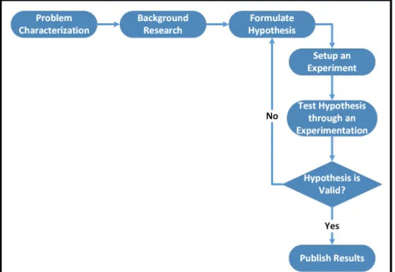
The work methodology applied in this master’s thesis is based upon the basic principles of the Scientific Method (Carey 2011), (Schafersman 1997). The methodology used is illustrated in Figure 1.1, and is composed of the following seven steps:
1. Problem Characterization
CHAPTER 1. INTRODUCTION
3. Formulate Hypothesis
4. Setup an Experiment
5. Test Hypothesis through an Experimentation
6. Hypothesis Validation
7. Publish Results
Figure 1.1: Overview of the Work Methodology used in this thesis.
1. Problem Characterization
The focal point in this step is the problem definition and its characteristics, which lead to a research question that will be the basis of the research work. It is already defined in 1.2.
2. Background Research
This step features the study of prior work related to information about the problem formulated in the first step. This study is based on a characterization, analysis and identification of a question. This approach provides the necessary tools for a starting point of the work itself. Awareness of what has already been accomplished facilitates the identification and justification of the progress that this work aims to accomplish.
1.4. DISSERTATION OUTLINE
3. Formulate Hypothesis
The hypothesis is focused on the background research and specifies a theoretical approach to solve the defined problem, which results in the setup of an experiment. In this master’s dissertation the hypothesis consists in an architecture which supports several tests for OBD systems.
4. Setup an Experiment
In this step the proof-of-concept is implemented to validate the hypothesis. This phase includes detailed planning and execution of the experimental approach to the technological architecture.
5. Test Hypothesis through an Experimentation
This step defines a series of tests to which the implementation will be submitted, according to the characteristics of the problem and formulated hypothesis. The tests must be executed in a controlled environment to ensure their quality. The data collected in each test must be interpreted and analysed in order to validate the previous hypothesis. If possible, qualitative and quantitative data analysis should be applied to the results.
6. Hypothesis Validation
After an extensive analysis of the results in the previous step, and taking into account the characteristics identified in the problem, the hypothesis must be validated. Results can enlarge hypothesis’s value or jeopardize all assumptions made in the beginning of the research. In case of failure, the original approach must be improve, and step 3 must be restructured.
7. Publish Results
This final step consists in publications of the successful results provided by the research work, as well as respective recommendations for further research. In order to make a contribution to the scientific community, the publication must be suitable for the type of research conducted. Scientific papers should be written to present intermediate results and a dissertation must be focused on the hypothesis. This master’s dissertation is the publication invoked in this step.
1.4
Dissertation Outline
CHAPTER 1. INTRODUCTION
also described, serving as a based start for the State-of-the-Art.
In addition to this chapter, the remainder of this dissertation is divided into five other chapters, each one with the following characteristics:
State-of-the-Art:Contains an overview about the previous related work concerning this thesis field. It is based on existing technologies, documents and studies which can help to better understand an subsequently problem, leading to a main Research Question.
Multiprotocol Architecture for OBD Emulator:The third chapter, relays on an exhaustive description of the architecture from its basic concept to its detailed logical specifications.
Experimental Setup:The fourth chapter, describes the supporting technologies that were used in order to perform the implementation, clarifying the OBD concept and defining all its requirements.
Implementation and Validation:This chapter contemplates a detailed view of the imple-mented solution which was based on the proposed architecture. The experimental results are presented and discussed.
Conclusions and Future Work:This document ends with the highlights of final thoughts and conclusions, describing the general impact about the developed work. Finally, it points the direction for future research works regarding the obtained results.
C
H
A
P
T
E
R
2
S
TATE
-
OF
-
THE
-A
RT
In order to start with a solid background, an extensive research was made to identify the current similar technologies and approaches related to this master’s thesis. Various solutions were identified but only five gets main focus with the finality to prepare a research question.
2.1
Review
This investigation keeps its major focus on integration and management of heterogeneous devices in an interoperable environment. Distributed and independent system with a heterogeneous integration and high scalability are eliminator criterion for the searched architectures.
The architectures studied are presented in alphabetic order:
• An IoT Gateway Centric Architecture to Provide Novel M2M Services: This research
proposes an innovative IoT architecture that allows real time interaction between mobile clients and smart sensors/actuators via a wireless gateway (Datta et al. 2014).
• Apache ServiceMix: It is an open source Enterprise Service Bus (ESB) that combines
CHAPTER 2. STATE-OF-THE-ART
• OpenIoT - Open Source cloud solution for the Internet of Things: It is an open source
middleware which communicates with sensor clouds in an independently and inter-operable way. This project handles and manage cloud environments composed by sensors, actuators and smart devices, offering efficient utility-based IoT services. Its provide cloud-based and utility-based sensing services, via an adaptive middleware framework (Soldatos et al. 2015).
• Universal Device Gateway: Develops and provides customized Information and
Communications Technology (ICT) solutions and services enabling among others the integration and management of a highly scalable and heterogeneous IoT. It is also a cross-domain integrator in compressing, energy efficiency, comfort, security and M2M automation, leading the way to a highly scalable network, from home, office building, up to smart cities and beyond (UDG Alliance 2016).
2.2
Individual Review
The next sections will present a detailed analysis about the previous studies.
2.2.1 An IoT Gateway Centric Architecture to Provide Novel M2M Services
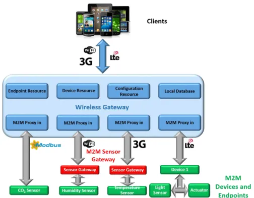
This project introduces an IoT gateway centric architecture in order to provide innovative and improved, Machine-to-Machine (M2M) services. The backbone of the proposed IoT architecture, shown in Figure 2.1, is performed by a Wireless Gateway (WG). The archi-tecture consists in three layers: sensing layers containing M2M devices and endpoints; a gateway API layer; and an application layer. The gateway contains a central database to store resource configurations of devices, endpoints and sensor metadata. Such implemen-tation of the mobile client and wireless gateway is highly applicable in personal health monitoring. The functionalities and APIs are broadly associated with two interfaces, north and south. The north interface communicates with mobiles clients and assists in discovery phase. The south interface manages and interacts with M2M devices and stores their configuration in a local database. The novel services offered by this architecture are:
• Dynamic discovery of M2M devices and endpoints by clients.
• Managing connection with non-smart things connected over modbus.
• Associate metadata to sensor and actuator measurements using Sensor Markup
Language (SenML) representation.
• Extending the current capabilities of SenML to support actuator control from mobile
clients.
2.2. INDIVIDUAL REVIEW
Figure 2.1: The proposed IoT Gateway Centric Architecture, based on (Datta et al. 2014).
Analysis
This approach proposes a solution, via wireless gateway, that allows device and ser-vice discovery; a standard protocol for endpoints integration; and mobile client control. The M2M devices and endpoints must register themselves in the gateway in order to be available to the mobile clients. This is made by a discovery phase which establish a connection to WG, allowing add or remove of M2M devices and endpoints, at real time. The API for the discovery phase is implemented in the gateway which is a novel solution provided by the architecture.
After the discovery phase, users can select, from a sensors list, the desired measure-ments to be received which are represented using SenML (Jennings et al. 2013). In order to contemplate the limited capabilities of M2M smart devices, SenML is a perfect solu-tion because of is lightweight, which provides an easily encode sensor measurements into different media types. Other advantage of SenML is its implementation by using JavaScript Object Notation (JSON) (ECMA-404 2013), enabling a server to efficiently parse huge numbers of sensor metadata at a very short time.
CHAPTER 2. STATE-OF-THE-ART
into SenML metadata. This approach also addresses actuator control from mobile clients. For that, SenML had to extend its capabilities in favor of address actuator control problems.
The APIs are based on the Representational State Transfer (REST), also known as RESTful web services (Fielding and Taylor 2000). The mobile clients are equipped with an applica-tion that receives measurements from sensors and can control actuators.
The M2M device receives requests from clients through Hypertext Transfer Protocol (HTTP). Afterwards there is a protocol that translates the HTTP data into M2M device specific command, make it understandable for the endpoints. In case of non-smart de-vices, the instructions received are converted into machine executable format by suitable mapping to a local database entry. The M2M proxy-in invokes an API which creates the desired SenML compliant metadata.This process can be assist by the Intermediate Sensor Gateway (ISG), helping in the creation of metadata and forwarding it to WG.
2.2.2 Apache ServiceMix
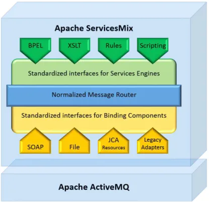
Apache ServiceMix is an open source implementation of an ESB in Java programming lan-guage. The main features of this architecture, shown in Figure 2.2, is to exchange messages from one component to another, as well as, the ability to route messages. It differentiates from other systems mainly because it reuses the communication channels, optimizing, in this way, the classical principles of connectivity and data exchange. ServiceMix fully supports the Open Services Gateway initiative (OSGi) (OSGi Alliance 2016) framework, which add an important feature to the architecture, modularity. That means that it can handle classloading and application lifecycle differently between components.
This architecture is present in Tecsisa, a company specialized in the development of solutions for the energy sector focusing on Service Oriented Architecture and cloud com-puting technologies (Tecsisa 2016). Not less important, GASwerk is an open source project which provides production ready solutions based on others open source components and it also uses ServiceMix (GASwerk 2016).
In order to standardize the ESB, Apache ServiceMix is builded on the Java Business Integration (JBI), which is defined by the JBI 1.0 Specification as"an architecture that allows the construction of integration systems from plug-in components, that interoperate through the method of mediated message exchange."(Ten-Hove and Walker 2005).
The imperative features which compose the ServiceMix are:
• ActiveMQ, to provide remoting, clustering, reliability and distributed failover.
2.2. INDIVIDUAL REVIEW
• JBI specification including: Normalized Message Router (NMR) which is a bus that
shuttles messages between the endpoints deployed on the ESB and JBI Management MBeans that expose management functions.
• Supports many communication protocols: File Transfer Protocol (FTP), HTTP, Java
Message Service (JMS), Simple Mail Transfer Protocol (SMTP), Simple Object Access Protocol (SOAP), Transmission Control Protocol (TCP), Extensible Messaging and Presence Protocol (XMPP).
• Supports many engines: Apache Camel, Apache CXF, Apache Orchestration Director
Engine (ODE), Scripting, Saxon XQuery, Extensible Stylesheet Language Transfor-mations (XSLT).
• Support for Security: Java Authentication and Authorization Service (JAAS), Web
Services Security (WSS).
• Web Container/App Server Integration: Geronimo, JBoss, Jetty, Tomcat, Weblogic,
Websphere.
Figure 2.2: Apache ServiceMix Architecture, based on (Snyder 2008).
Analysis
CHAPTER 2. STATE-OF-THE-ART
ubiquitous integration backbone through which software services and application components flow."(Thomas 2007).
This architecture implements ESB through JBI, which describes all components with Java terminology and interfaces. This enables the integration of services in an independent way, allowing the plug and play concept. The JBI standard allows the manage of data translation and routing.
The messages exchanged in this architecture are embedded with the interoperability concept in order to connect external systems to the bus. This requires a standard trans-lation of messages, called Normalized Message, which contains the actual data, along with various properties and destination endpoint. Normalized Message, typically contains Extensible Markup Language (XML) data, but is not restricted to it, being also possible to attach binary information to the message. The NMR has the responsibility to transport the message to its final destination. When the Normalized Message leaves the NMR, it’s converted to what is understood by the target system.
2.2.3 OpenIoT - Open Source cloud solution for the Internet of Things
OpenIoT is similar to an extension of cloud computing implementations, which is focused on the Internet of Things based resources and capabilities. OpenIoT includes and interre-lates three important IoT technological areas: Middleware for sensors and sensor networks; Ontologies, semantic models and annotations for representing internet-connected objects; and Cloud/Utility computing. This architecture, illustrated in Figure 2.3, is constituted by seven main elements that belong to three different logical planes:
1. Utility/Application Plane
• Request Definition: Enables on-the-fly specification of service requests to the
OpenIoT platform by providing a Web 2.0 interface. It comprises a set of services for specifying and formulating requests, while also submitting them to the Scheduler.
• Configuration and Monitoring: It enables visual management and
configura-tions of functionalities over sensors and services that are deployed within the OpenIoT platform.
• Request Presentation: It is in charge of visualization for service outputs. In
order to visualize these services, it communicates directly with the Service Delivery & Utility Manager to retrieve the relevant data.
2.2. INDIVIDUAL REVIEW
2. Virtualized Plane
• Scheduler: It processes all requests for services from the Request Definition
and ensures its proper access to the resources required. This component under-takes the following tasks: it discovers sensors and associated data streams that can contribute to a given service; it also manages a service and activates the resources involved in its provision.
• Cloud Data Storage: It enables the storage of data streams stemming from the
sensor middleware, thereby acting as a cloud database. The cloud infrastructure stores also the metadata required for the operation of the OpenIoT platform.
• Service Delivery & Utility Manager: On the one hand, it combines the data
streams as indicated by service workflows within the OpenIoT system in order to deliver the requested service either to the Request Presentation or a third-party application. On the other hand, this component acts as a service metering facility, which keeps track of utility metrics for each individual service.
3. Physical Plane
• Sensor Middleware: It acts as a hub between the OpenIoT platform and the
physical world. The Sensor Middleware is deployed on the basis of one or more distributed instances, which may belong to different administrative entities. The prototype implementation of the OpenIoT platform uses the Global Sensor Networks (GSN) sensor middleware that has been extended and now called X-GSN.
CHAPTER 2. STATE-OF-THE-ART
Analysis
This architecture provides an open source IoT platform enabling the interoperability of IoT services in the cloud. The central feature of OpenIoT is Semantic Sensor Networks (SSN) ontology (Compton et al. 2012), which provides a common standards-based model for representing physical and virtual sensors. The implementation of the ontology and its integration in the OpenIoT architecture are realized through the Linked Stream Mid-dleware (LSM) (Le-Phuoc et al. 2011). LSM translates the data from virtual sensors into Linked Data stored using Resource Description Format (RDF).
In order to manages the registration, data acquisition, deployment of sensors and in-terconnected objects over LSM, this approach provides the X-GSN. The GSN is a flexible middleware layer which abstracts from the underlying, heterogeneous sensor network technologies. It supports a fast and simple deployment of new platforms, facilitates effi-cient distributed query processing and combination of sensor data. This provides support for sensor mobility, and enables the dynamic adaption of the system configuration during runtime with minimal effort. The core concept in X-GSN is the virtual sensor. This enables sensor heterogeneity between abstract and concrete entities (GSN Team 2014).
The data acquisition for each virtual sensor is provide by wrappers that collect data through serial port communication, User Datagram Protocol (UDP) connections, HTTP requests, Java Database Connectivity (JDBC) queries, and more. In order to receive data from various data sources, X-GSN implements wrappers and allows users to develop custom ones.
Other advantage of this architecture is its visual tools that enable the development and deployment of IoT applications with almost zero programming.
2.2.4 Universal Device Gateway
Universal Device Gateway (UDG) is a open source, highly scalable, portable, multiproto-col, control and monitoring system for the IoT. It communicates with all sorts of devices, protocols and standards, enabling multiprotocol and cross-domain interoperability. The integration of several devices and protocols generates a flexible interoperable system.
This approach simplifies the harmonization of heterogeneous system with Machine-to-Machine communication. It brings flexibility and easiest evolution of existing deployments by integrating devices through unique Internet Protocol version 6 (IPv6) addresses. Its benefits from high skill capability with approximately 3.4×1038public addresses. That is
more than enough to provide each smart device deployed with an unique address.
2.2. INDIVIDUAL REVIEW
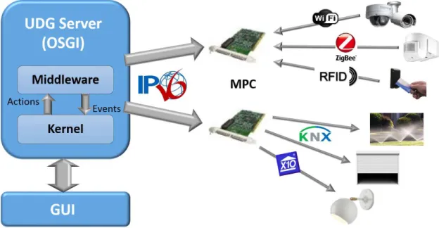
The UDG architecture, shown in Figure 2.4, enables an integration with the global internet and cloud, including Software as a service (SaaS), web application and smart things infor-mation Services. Other distinctive characteristic of UDG is its portability and heterogeneity which can be easily deployed in various hardware, in order to distribute intelligence across the whole network of smart things. This results in the absence of bottlenecks and an unique point of failure.
Figure 2.4: Universal Device Gateway architecture, based on (Bocchi et al. 2012).
Analysis
One of the most differentiating features of this approach is its IPv6 based technology. This enables high scalability and powerful mechanisms such as auto-configuration, multi-cast, anycast and mobility. On the safety level, Internet Protocol Security (IPsec), provides strong security and authentication mechanisms.
This architecture is compliant with IPv6 and M2M, providing interoperability with over 40 communication protocols. In order to allows heterogeneity, UDG permits an unique IPv6 and M2M proxy, enabling bi-directional interactions between non-IP systems and IPv6/M2M standards. Each devices gets its own and unique IPv6/M2M address.
Another important characteristic of this approach is its portability, enabling various hard-ware, from Raspberry-Pi to routers and servers. This results in the absence of bottlenecks and unique point of failure.
CHAPTER 2. STATE-OF-THE-ART
remote monitoring, alerts management, third parties SaaS and web services integration.
From the architectures studies the one which concretely grants a future scalable interoper-ability between systems it is the UDG because of its IPv6 oriented service based. However the IPv6 adoption among Google users is 10% at the moment that this thesis was written (IPv6 Google -). Therefore, it is a solution to take in high count for the future but has some limitations at the moment.
2.2.5 Synthesis
A first look at all four researches it is evident that Wireless Gateway (WG) and Universal Device Gateway (UDG) approaches focuses more on the Machine to Machine (M2M) devices. On the other hand, ServiceMix and OpenIoT are more comprehensive, being even able to manage virtual and pyhsical sensors.
The discovery device phase problem is one of the most discussed in all four architec-tures presents in this chapter. Excluding UDG, which seems to work with servers based on OSGi, all others three systems has its own discovery device system. In this specific case the WG architecture brings a novel discovery system implemented on the gateway, allowing a dynamical discover at real time. The OpenIoT approach, also stands out with its Scheduler system where X-GNS records all devices.
Another recurrent problem covered in this studies is the data translation. All four ap-proaches deals with this problem on a proper way. However two of them differentiate from the others: ServiceMix with Normalized Message, which converts data to XML, and OpenIoT with X-GNS which introduces the wrappers concept.
Multiprotocol communication is addressed in all architectures, except WG which seems to only use HTTP. ServiceMix, introduces its NMR and OpenIoT with IPv6 protocol enables an heterogeneous communication systems.
Besides WG approach, which seems to relegate that to future work, all the others archi-tectures have they security systems based on authentication and time expiration session. The API role on OpenIoT offers a different approach being composed by visual tools with almost zero programming. RESTful web services and SaaS are respectively addressed in WG and UDG architecture as API services.
Concerning modern architectures and flexibility, WG and OpenIoT are one step ahead of UDG and ServiceMix. On the other hand, WG, UDG and OpenIoT offers features suitable to be executed in devices with limited resources. The architectures which use a model-based development guide are OpenIoT and ServiceMix.
2.2. INDIVIDUAL REVIEW
C H A P T E R 2. ST A T E -O F -T H E -A R T
Table 2.1: Overview of the State of the Art Research
Main Feature
Modern and flexible archi-tecture
Run in devices with limited re-sources
Model-based Main technicalapproaches
WG
HTTP requests
and Modbus
Yes Yes No JSON
ServiceMix Reuse Concept(ESB) No No Yes MDE
OpenIoT Allows Virtual
Sensors Yes Yes No Wrappers
UDG IPv6 based No Yes No Software as a
Service
2.3. MAIN TECHNICAL APPROACHES
2.3
Main technical approaches
In this section the main technical approaches will be scrutinized in detail.
2.3.1 JSON
The JavaScript Object Notation (JSON) is an open-standard text format that facilitates structured data interchange between all programming languages and is the most com-mon data format used for asynchronous browser/server communication. It derives from JavaScript code to generate and parse the JSON-format data (Bray 2014).
JSON is agnostic about numbers, what can make interchange between different pro-gramming languages difficult. It offers only the representation of numbers that humans use, like a sequence of digits. Due to the fact that all programming languages know how to make sense of digit sequences, even if they disagree on internal representations, inter-change can be guaranteed.
The JSON text is a sequence of Unicode code points which provides support for or-dered lists of values. Because objects and arrays can nest, trees and other complex data structures can be represented. By accepting JSON’s simple convention, complex data structures can be easily interchanged between incompatible programming languages.
This open-standard text format does not support cyclic graphs and is not indicated for applications requiring binary data.
It is expected that other standards will refer to this one, strictly adhering to the JSON text format, while imposing restrictions on various encoding details. Such standards may require specific behaviours since JSON itself specifies no behaviour (ECMA-404 2013).
2.3.2 Wrappers
The GSN can receive data from various data sources and this is done using wrappers, shown in Figure 2.5. They are used to encapsulate the data received from the data source into the standard GSN data model. This process is called StreamElement, which is an object representing a row of a SQL table.
CHAPTER 2. STATE-OF-THE-ART
The received data has been mapped to a SQL data structure with fields that have a name and a type. GSN is then able to filter this using SQL syntax (GSN Team 2014).
Figure 2.5: An example of a wrapper functionality, based on (GSN Team 2014).
2.3.3 Model Driven Engineering
The basic concept of Model Driven Engineering (MDE), also known as Model Driven Development (MDD) is to address everything as a model, which is characterized by the OMG with a:"set of information about a system that is within scope, the integrity rules that apply to that system, and the meaning of terms used."(OMG 2014). MDE is an open and integrative
approach that embraces a set of associated concepts, body of knowledge, tools, required skills, and possibilities. It simplifies complex systems in several activities and tasks that comprise an information system life cycle. In this way it is possible to maximize compati-bility between systems and promoting communication between developers, increasing productivity.
An enterprise is constituted by business processes, services, information, resources, etc. Each of this core features has an important role describing a model. A single model can be described as a set of expressions composed by information about a system. A model is exposed in a model notation or language and can be visual or textual. A language de-scription contains an abstract syntax, one or more concrete syntax dede-scriptions, mappings between abstract and concrete syntax, and a description of the semantics. The abstract syntax of a language is often defined using a metamodel. In this case a metamodel can be
2.3. MAIN TECHNICAL APPROACHES
defined as a modeling language (Schmidt 2006).
MDE supports models at different levels of abstraction, from high-level business models, focusing on goals, to complex scenario models, for business execution. Subsequently, quality is an important aspect of MDE, which can be guaranteed with: model validation, model checking, and model-based testing (OMG 2014).
Normaly, MDE is often confused with Model Driven Architecture (MDA). However according to Favre (Favre 2004) MDA can be seen as a specific incarnation of the MDE approach. Comparing MDE and MDA it can be concluded that the last one is more focuses on technical software heterogeneity and how to specify a software in independent way within a platform (Kent 2002).
The MDE approach can be define in three different abstractions levels of information:
• Computation Independent Model (CIM), is actually called, by OMG, a Business or
Domain model and it specifies the requirements for the system and environment where it will operate. All of that defines the function of a system without showing constructional details and plays an important role doing a bridge between business, design and IT experts. In order to provide the business needs, CIM, only describes business concepts whereas a PIM may define a high-level systems architecture.
• Platform Independent Model (PIM), is the formal specification of a system from
the platform independent viewpoint. In order to be suitable for several different platforms of similar type, it specifies a system without implementation details.
• Platform Specific Model (PSM), can be defined as a more detailed version of PIM.
This platform associates the specifications in PIM with technical details and imple-mentations that are available in a system. That influences how such system uses a particular type of platform, which includes middleware, operating systems and programming languages.
The input and output of each model must be defined as metamodels and as well classified according to the metamodelling level they belong, which brings optimized interoperability benefits (Kent 2002; OMG 2014).
CHAPTER 2. STATE-OF-THE-ART
The first one, does not affect the abstraction level leading to enable collaborative ac-tivities and interoperability benefits. However the language associated between systems needs to have its specifications well define. On the other hand, Vertical Transformations necessarily implies a change on the abstraction level of the resulting model, affecting its specifications. Vertical transformation tools provide a mechanism to perform model annotations and means to customize the transformation rules according to the user need. They also provide a pre-defined PSMs which influences, along with the code generator, the amount of generated code (OMG 2014).
2.3.4 SaaS - Software as a Service
In the software as a service model, the application, or service, is deployed from a central-ized data center across a network providing access and use on a recurring fee basis. Users "rent," "subscribe to," “are assigned”, or "are granted access to" the applications from a central provider. Business models vary according to the level to which the software is streamlined, to lower price and increase efficiency, or value-added through customization to further improve digitized business processes.
The core value of software as a service is providing access to, and management of, a commercially available application. The potential benefits of the model are significant for both the vendor and the customer.
2.4
Remarks
Multiprotocol is one of the features more approached in this study and the majority of systems fulfill the necessary specifications of IoT architectures. WG not specifies concretely the protocols communication allowed except for non smart devices, where it uses Modbus.
All approaches uses Web Services or OSGI, which grants that all kinds of users can access the network, by different operating systems and using different devices. Nonethe-less WG seems to be still in a early phase of development and do not fully guarantee access rights for multiple users and security & privacy.
In all researches has a mature development for the discovery device feature but Ope-nIoT platform only allows the creation of sensor types called gsn. This is a major issue and limitation as sensors like soil moisture, weather, etc. cannot be discovered (Soldatos et al. 2015).
All the systems referred earlier are not able to fully solve the characteristics of a multipro-tocol OBD emulator architecture. Different functionalities of each system were extracted
2.5. RESEARCH QUESTION
from all of them, in order to identify a problem, respective hypothesis and creating a unique solution capable of fulfilling all the requirements exposed.
2.5
Research Question
In order to create successful On-Board Diagnostics applications, it is inevitable ensure an exhaustive test system which improves user interaction among different environments. However, experiments with vehicles are not economically viable because of possible manipulation in car sensors and actuators. Errors are unavoidable during tests and ma-nipulating sensitive aspects in vehicle could jeopardize the security of users.
In favour of overcoming this issue there are some commercial solutions which simu-late OBD behavior to controllable car data inputs. Upon analyzing OBD simulators in the current market there is a common point between them: the price. In general, OBD simulators are expensive and do not offer all main protocols in their basic kit. For instance, the ECUsim 2000 OBD-II ECU Simulator, from OBD Solutions enterprise, offers many in-teresting characteristics but with only one communication protocol it costs approximately 178e(OBD Solutions -a).
On the other hand, non-commercial solutions where users can manipulate and customize every aspect of their applications are in the line of an unexplored market. For the author of this master’s thesis and until the date that it was written there is no solid academic or independent work which allows the development of projects in a low-cost non-commercial OBD simulator. There a gap on the IoT community for a specific project which addresses this field with open source technology.
These facts leads to the following research question, which supports this master’s thesis:
How a multiprotocol architecture can assist on the developement of new and interoperable OBD systems?
This problem presents a set of characteristics that needs to be addressed:
• Modernity and Flexibility: The architecture must be flexible and capable to evolve
in order to accommodate more protocols that may appear in the future. In this sense, there is a need for modern, flexible and plug-and-play approaches.
• Model-based: The system needs to concern a model-based development and domain
CHAPTER 2. STATE-OF-THE-ART
• Light format: There is a need for simple architectures with small time and spatial
footprints that can be executed in small devices. The output services must come in a standardised frame which can grant interoperability in a light format allowing access to different kinds of devices.
C
H
A
P
T
E
R
3
M
ULTIPROTOCOL
A
RCHITECTURE FOR
OBD
E
MULATOR
This chapter proposes a possible solution to the Research Question introduced previously. The suggested architecture is exhaustively described from its basic concept to its logical specifications. In order to have a clearly overview of this approach it is important to clarify the difference between emulator and simulator. In the author perspective, emulation concept is linked to the duplication of inner workings in a system. On the other hand a simulation tries to duplicate the behaviour of a system. In other words, emulators replicate the original usage of a software or hardware and simulators are an environment of test models with the purpose of analysis and study.
3.1
Hypothesis
Based on the background observation summarized on chapter 2 and in order to satisfy the demands of the research question, it is believed that the following hypothesis could be the answer to the mentioned problematic.
If a Model-based approach is followed, other systems can import these formal descriptions, then new and interoperable OBD systems can be developed.
CHAPTER 3. MULTIPROTOCOL ARCHITECTURE FOR OBD EMULATOR
3.2
Concept
The idea behind OBD Emulator is the development and testing of OBD applications. This system provides external control in a standard OBD port which simulates the output signals of a vehicle’s Electronic Control Unit (ECU). The major advantage for developers is to avoid real connection to an actual vehicle with the purpose of testing and validation of new solutions. This concept also allows common persons to access vital information in a vehicle without expert assistance.
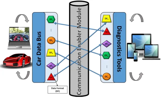
The general idea is to design a method which enables communication between two different systems. In this particular case, one system symbolizes a car and other system represents a diagnostic tool which acquires car data. It is crucial to have an integration platform in order to guarantee interoperability for physical interfaces and data formats. The Figure 3.1 shows the concept designed for the OBD Emulator.
Figure 3.1: OBD Emulator Concept.
This concept relies in sending requests, trough a smart device, over the avaiable Diagnos-tics Tools. These mechanism translates the previous requests to a specific Data Format (DF). Afterwards, forwards it through the Communication Enabler Module (CEM) to other DF, on the car driving simulator side.
The CEM operates as a bridge between devices and car driving simulators. It is responsible for the interoperability among differents DFs and allows communication in an heteroge-neous environment.
3.3. ARCHITECTURE OVERVIEW
Requests/replies are received respectively on the Car Data Bus and Diagnostics Tools, through DFs. These two modules manages requests and respective replies, coding/de-coding the data acquired from car driving simulators or devices (e.g: computers, smart phones), in the available DFs.
3.3
Architecture Overview
At this point it is possible to address the essential module of an OBD emulator architecture, which intends to test the presented hypothesis. It is reasonable to conclude that the above approach is centralized in CEM, therefore it will be scrutinized in next section. The archi-tecture overview in CEM, uses three different logical modules as illustrated in Figure 3.2. A brief description of each individual modules is presented next.
Figure 3.2: Communication Enabler Module.
Communication Protocols Handler (CPH), works as an interface for all communication modules, providing necessary tools for establish connection between incoming and out coming data and the Transformation Engine Module.
Transformation Engine is a central communication bridge in the architecture, receives requests/replies and forwards them from one to other CPH module. It transforms Data Formats according to actual requirements, specifications enabling interoperability between each others.
CHAPTER 3. MULTIPROTOCOL ARCHITECTURE FOR OBD EMULATOR
3.4
Logical Architecture Specification
In the next section is presented a brief description of functionalities and characteristics of each logical module.
3.4.1 Communication Protocols Handler
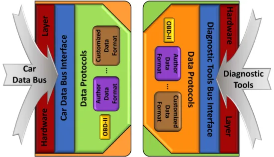
The logical module Communication Protocols Handler (CPH) is responsible for providing system connection with the outside systems data bus, using available data formats to communicate. Data formats can be added or removed independently, not compromising the system. The CPH is composed by three logical sub-modules: Hardware Layer, Car Data Bus Interface or Diagnostic Tools Bus Interface and Data Protocols.
The module composition, showed in Figure 3.3, has input information from the vehi-cle by a bus called Car Data Bus. There is also other CPH module with a similar function but with diagnostic requests data as input. In this way, it is assured bidirectional commu-nication between these two modules.
Figure 3.3: Communication Protocols Handler modules.
The Hardware Layer assures support to other sub-modules with all the physical features necessary for communication. It is constitute by communications protocols (e.g.: tcp/ip, CAN) and their respective physical interfaces (e.g.: ethernet, CAN interface).
The Car Data Bus Interface and Diagnostic Tools Bus Interface are a connection bridge be-tween outside data and the Transformation Engine.
3.4. LOGICAL ARCHITECTURE SPECIFICATION
Finally, the sub-module Data Protocols has the ability to interpret data and arrange them according to the required model specifications (e.g.: OBD-II). This sub-module allows to identify incoming data formats, standard or new ones made by developers, which is an important feature of this architecture, since it is capable to retrieve new data models from the storage module and therefore identify new/different incoming Data Protocols. The author of this thesis customized his own data format, described in chapter 5.
3.4.2 Transformation Engine
The Transformation Engine enables communication between different data formats, trans-forming them in order to be understandable to the receiver DF.
This module receives data from the CPH, in one DF from its list, and transform it (accord-ingly to specified rules) to a target DF in order to be successfully received on the other CPH. The target CPH can contain or not the same source data format. Communication will always be assured by the Transformation Engine module, even between different data formats.
Modulation is the key feature in this transformation and it is supported by rules and models. The module composition is showed in Figure 3.4.
Figure 3.4: Transformation Engine module.
CHAPTER 3. MULTIPROTOCOL ARCHITECTURE FOR OBD EMULATOR
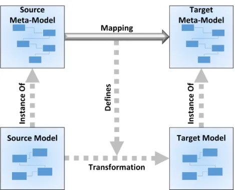
so data can be transform from one format to another. To achieve data conversion, two levels of abstraction must be defined to use the Model Driven Architecture (MDA). The Platform Independent Model (PIM) and Platform Specific Model (PSM). These meta-models concepts are already described in subsection 2.3.3 - Model Driven Engineering.
The explained concept is represented in the next Figure 3.5.
Figure 3.5: A transformation example between two Data Formats.
Succinctly, the mapping between a source meta-model and a destination meta-model generates rules. These rules are applied in the transformation of a source model in order to obtain a target model.
3.4.3 Database
The Database is a repository used to store models that describe data formats and also rules needed to transform a source data model to an target data model. Acting as a repository the DataBase also allows new models to be added, as well as, the corresponding rules necessary for transformation from one source model can be held for different target models.
3.5. ARCHITECTURE COMPOSITION
3.5
Architecture Composition
All together the logical modules described in the previous section with their interfaces provide a new approach to represent the Multiprotocol OBD Emulator Architecture, as showed in Figure 3.6
C
H
A
P
T
E
R
4
E
XPERIMENTAL
S
ETUP
This chapter describes supporting technologies that were used in order to perform the implementation. It clarifies the On-Board Diagnostics (OBD) concept and defines all implementation requirements. Finally, an overview of all experimental setup is described.
4.1
On-Board Diagnostics
On-Board Diagnostics (OBD) is an electronic diagnostic system which has the capacity to receive information transmitted from car sensors. This sensors, controlled by Electronic Control Unit (ECU), are designed to ensure the security of several car subsystems. The ECU controls all the fundamental systems of the car, such as, automatic transmission, drive system, brake system, and steering system. The sensors parameters analysed are used by the ECU, ensuring the safety and efficient operation of the vehicle. Usually it takes more time to diagnose a problem in a vehicle than to rectify it and through this systems it is possible to do an efficient diagnose, saving time (Zaldivar et al. 2011).
The OBD standards were developed to detect car engine issues that can provoke gas emission levels beyond acceptable limits. The first OBD generation, known as OBD-I, did not establish a specific emission level for vehicles and only a few diagnostic parame-ters were defined. However the major disadvantage was the non-standardization, what brought a different OBD system to each car brand.
CHAPTER 4. EXPERIMENTAL SETUP
by the Society of Automotive Engineers (SAE) and International Organization for Stan-dardization (ISO), who standardized five different protocols: SAE J1850 PWM, SAE J1850 VPW, ISO 9141-2, ISO 14230 KWP2000, and ISO 15765 CAN. These protocols have signifi-cant differences between them in terms of the electrical pin assignments. Since 2008, the majority of vehicles are equipped with the ISO 15765-4 CAN protocol or just Controller Area Network (CAN), due to a greater flexibility, immunity to noise and speed.
Diagnostic Trouble Codes (DTC) were strongly regulated, allowing technicians to easily determine the reason of a vehicle malfunctioning, using generic scanners. The proposed format, assigns alphanumeric codes to different causes of failure, although extensions to the standard are allowed to support manufacturer-specific failures.
The adoption of different message priorities was an important improvement in the OBD-II data format, in order to make sure that critical information is processed first. The frame formats allow up to 7 data bytes and include a checksum field to detect transmission errors (Hasan et al. 2011).
The OBD communication is stablish via OBD-II connector, represented in Figure 4.1, which allows the transmission and reception of codes. The Parameter ID (PID), are the serial of codes used to request data from vehicles. SAE standard J-1939 defines many PIDs, but manufacturers also customized they own specific PIDs to their vehicles. After sending the PID request, the scan tool sends it to the vehicle’s through the pre-defined OBD protocol (CAN, PWM, VPW, KWP or OBD Standards). A device on the car’s bus recognizes the respective PID and reports with a reply value of it to the bus. Finally the scan tool reads the response, and displays it in an appropriate device.
Figure 4.1: OBD-II connector and respective pinout.
4.1. ON-BOARD DIAGNOSTICS
Each PID is characterized by its mode, code, number of returned bytes, minimum value, maximum value, units and correspondent formula. On the SAE standard, J-1939, the PIDs codes are subdivided per ten different Modes (in hexadecimal):
• 01 - Show current data;
• 02 - Show freeze frame data;
• 03 - Show stored Diagnostic Trouble Codes;
• 04 - Clear Diagnostic Trouble Codes and stored values;
• 05 - Test results, oxygen sensor monitoring (except CAN);
• 06 - Test results, other component/system monitoring (Test results, oxygen sensor
monitoring for CAN only);
• 07 - Show pending Diagnostic Trouble Codes (detected during current or last driving
cycle);
• 08 - Control operation of on-board component/system;
• 09 - Request vehicle information;
• 0A - Permanent Diagnostic Trouble Codes.
The communication is provided by the referred five protocols, however there are common points in each data frame sent. All data requests might contain the number of additional data bytes, the Mode and PID Code. On the other hand, the response data must have all referred bytes and a value for the specified parameter. Afterwards, the final value is calculate by its correspondent formula.
For instance, lets consider a CAN communication for current data of engine coolant temperature, where there is a Request data frame and a respective Response, represented in the example of Figure 4.2. The Request data frame is composed by: the value 2 in position 0 which represents two additional data bytes, Mode 01 in position 1 and the PID code 05 for engine coolant temperature, in position 2. The remain 5 positions are not used and in CAN protocol may be 55 in hexadecimal.
CHAPTER 4. EXPERIMENTAL SETUP
The next Figure 4.2, presents a request and respective response data frame for current data of engine coolant temperature. The example represents CAN data frames, scrutinized in section 5.1.
Figure 4.2: Request/Response CAN data frames.
4.2
Supporting Technologies
Before execute the planned implementation it is necessary to define its requirements. This section describes the technologies used in order to perform experiments, from software side to hardware one.
4.2.1 Hardware
In the next subsection it will be define all hardware technologies used during the imple-mentation.
4.2.1.1 OBD Scanner
OBD scanner is an electronic tool used to interface with vehicles control modules. The OBD scan tool is connected to the vehicle’s Data Link Connector and reads out Diagnostic Trouble Codes. It allows to transmit/receive data between the five OBD communication protocols and the vehicle. However, this data can be accessed, by the user, via serial or preferably, wireless. With the purpose of chose an adequate OBD Scanner it was prede-fined a few characteristics: inexpensive, multi-platform for the main OBD-II protocols and smart devices. These characteristics justified the choice by ELM327 Interface Bluetooth version, shown in Figure 4.3, with an approximately price of 3.58e1.
1Available athttps://goo.gl/QBLv1q- Accessed 21/08/2016.