Lígia Regina Tomás Coelho
BSc. Biochemistry, FC-ULVascularization: plant decellularization and
electrospinning techniques for the development
of small and medium caliber blood vessels
Dissertation submitted in partial fulfillment of the requirements for the degree of
Master of Science in Biochemistry
Adviser: Jorge Carvalho Silva, Assistant Professor, NOVA University of Lisbon
Co-adviser: Carla Pinheiro, Assistant
Professor, NOVA University of Lisbon
Examination Committee
Chairperson: Prof. Dr. José Ricardo Ramos Franco Tavares Raporteur: Dr. Ana Margarida da Costa Macedo Fortes
Vascularization: plant decellularization and electrospinning techniques for
the development of small and medium caliber blood vessels
Copyright©Lígia Regina Tomás Coelho, Faculty of Sciences and Technology, NOVA Uni-versity Lisbon.
The Faculty of Sciences and Technology and the NOVA University Lisbon have the right, perpetual and without geographical boundaries, to file and publish this dissertation through printed copies reproduced on paper or on digital form, or by any other means known or that may be invented, and to disseminate through scientific repositories and admit its copying and distribution for non-commercial, educational or research purposes, as long as credit is given to the author and editor.
This document was created using the (pdf)LATEX processor, based in the “novathesis” template[1], developed at the Dep. Informática of FCT-NOVA [2].
Ack n o wl ed gemen ts
This thesis could never have come to fruition without the help of some amazing people who I was lucky enough to come in contact with along this entire year. This work is dedicated to them.
To the ladies at the Molecular Ecophysiology Lab at ITQB, Dr. Ana Fortunato and Dr. Olfa Zarrouk, for all the support and valuable suggestions given to me throughout the time I was there. A special thanks to Dr Ana for taking the time out of her busy schedule to guide me through the booking protocols of equipment, teach me about how everything works and especially, watering my plants on the days I couldn’t go to the institute, so I could finish an experiment at the faculty.
To professor Pinto Ricardo at the Plant Biochemistry Lab at ITQB, for his help choosing and identifying plant varieties and always being interested on the project.
To Dr Susete Fernandes from the Polymeric and Mesomorph Materials Group at FCT-UNL, for helping me with the contact angle measurements and teaching me about the process. To all the lab technicians and researchers who have aided me along the way, be it by their work or simple advice, with a special thanks to Hugo Matias for all his greenhouse help during the plant growth step.
To my lab colleagues Diana Querido, Bruno Guerreiro, Daniela Fernandes and Jeniffer Farias for making the hard days when nothing seemed to work much more bearable.
To my partner, David Moreira, for saving me multiple times from some serious informatics mishaps, for all the support and times he’s helped me transport my work from the institute to the university.
Ab s tr act
Vascularization in complex human tissues remains a challenge in the field of tissue engineering. A functional vascular network, capable of providing oxygen and nutrients and the removal of metabolites, is mandatory for the regeneration of large organs. Recent research on whole organ decellularization has showcased advantages regarding biocompatibility and structural integrity on the resulting extracellular matrix. In this work, we explored the possibilities of two different scaffold building techniques, plant decellularization and fibre electrospinning, as natural and synthetic alternatives for the issue of vascularization. Tetragonia tetragonioides
(Pallas) Kuntze,Spinacia oleraceaL. andPhaseolus vulgarisL. leaves were successfully decellu-larized, with a nucleic acid reduction of 89±11 %, 99.0±1.0 % and 99.6±0.4 % respectively.
The structural integrity was highest forT. tetragoniodes. Re-seeding of the leaves with 3T3 fibroblasts and endothelial cells by conventional seeding and a perfusion re-cellularization forS. oleraceawith 3T3 cells were also achieved. In parallel, we were able to produce poly-caprolactone scaffolds interleaved with open channels and evaluate their cellular adhesion and proliferation. A three channel scaffold alongside thick polycaprolactone layers provided the best results. The scaffolds studied in this work may provide effective re-vascularization strategies upon incorporation in large-scale scaffolds for organ regeneration.
Keywords: Tissue engineering, ECM, 3T3, endothelial cells, PCL, PEO,Phaseolus vulgarisL.,
R es u mo
A vascularização em tecidos humanos complexos permanece um desafio no ramo de enge-nharia de tecidos. A existência de uma rede vascular que providencie oxigénio e nutrientes, bem como a remoção de metabolitos é essencial à regeneração de órgãos. Desenvolvimentos recentes acerca da descelularização de órgãos têm demonstrado vantagens relativamente à biocompatibilidade e integridade estrutural da matriz extracelular resultante. Neste trabalho, explorámos as possiblidades de duas técnicas de fabricação de scaffolds, a descelularização vegetal e a electrofiação de fibras, como sendo alternativas naturais e sintéticas ao problema da vascularização. Folhas deTetragonia tetragonioides(Pallas) Kuntze,Spinacia oleraceaL. e Pha-seolus vulgarisL. foram descelularizadas com sucesso, com uma redução de conteúdo de ácidos nucleicos de 89±11 %, 99.0±1.0 % e 99.6±0.4 % respectivamente. A integridade estrutural
foi superior paraT. tetragonioides. Foi possível efetuar oseedingde folhas com fibroblastos 3T3 e células endoteliais por seeding convencional bem como por perfusão de folhas deS. oleracea
com células 3T3. Em paralelo, foram produzidos scaffoldsde policaprolactona intercalados com canais abertos e avaliada a sua adesão e proliferação celular. Os melhores resultados foram obtidos para umscaffoldde três canais juntamente com camadas espessas de policaprolactona. Osscaffoldsutilizados neste trabalho poderão ser uma estratégia eficaz de re-vascularização quando incorporandas emscaffoldsde larga escala para a regeneração de órgãos.
Palavras-chave: Engenharia de tecidos, 3T3, células endoteliais, ECM, PCL, PEO,Phaseolus
C o n ten ts
List of Figures xix
List of Tables xxiii
Glossary xxv
Acronyms xxvii
1 Introduction and Objectives 1
1.1 Vascularization . . . 2
1.1.1 In VivoPre-vascularization . . . 2
1.1.2 In VitroPre-Vascularization . . . 2
1.1.3 Scaffold Design . . . 3
1.2 The Extracellular Matrix . . . 4
1.2.1 The Animal ECM . . . 4
1.2.2 The Plant ECM . . . 6
1.3 Plant Leaf Anatomy . . . 8
1.3.1 Leaf Tissues . . . 8
1.4 Blood Vessel Anatomy . . . 11
1.5 Tissue decellularization . . . 12
1.5.1 Chemical Decellularization Agents . . . 13
1.5.2 Enzymatic Methods . . . 15
1.5.3 Physical Agents . . . 16
1.5.4 State of the art . . . 17
1.6 Electrospinning . . . 20
1.6.1 Polycaprolactone . . . 21
1.6.2 Polyethylene Oxide . . . 23
1.7 Work plan and Objectives . . . 24
2.1.1 Plant germination and growth . . . 25
2.1.2 Plant leaf conservation and transportation . . . 26
2.1.3 Plant leaf decellularization . . . 28
2.1.4 Plant histology . . . 30
2.1.5 Optimization of the decellularized material . . . 31
2.1.6 Mechanical Tests . . . 31
2.1.7 Scaffold DNA assessment . . . 31
2.2 Electrospinning . . . 33
2.2.1 Condition screening . . . 33
2.2.2 Construction of the layered scaffolds . . . 33
2.3 Cellular Assays . . . 35
2.3.1 Scaffold seeding . . . 35
2.3.2 Perfusion re-cellularization . . . 35
2.3.3 Resazurin tests . . . 36
2.4 Imaging techniques . . . 38
2.4.1 Nuclei staining imaging . . . 38
2.4.2 Scanning Electron Microscopy . . . 38
3 Results and Discussion 39 3.1 Plant leaf decellularization . . . 39
3.1.1 Seed germination . . . 39
3.1.2 Plant growth patterns . . . 41
3.1.3 Plant leaf conservation and transportation . . . 44
3.1.4 Decellularization procedures . . . 47
3.1.5 DNA quantification and agarose gel . . . 55
3.1.6 Mechanical Tests . . . 56
3.2 Electrospinning . . . 58
3.2.1 Condition screening . . . 58
3.2.2 The hydrophobicity of PCL: Contact angle measurement . . . 61
3.3 Cellular Assays . . . 62
3.3.1 Resazurin cell viability screening . . . 62
3.3.2 Decellularized leaf scaffolds . . . 63
3.3.3 Electrospun scaffolds . . . 72
3.3.4 Leaf and Fibre Scaffold SEM imaging . . . 78
4 Conclusions and Future Perspectives 83 4.1 Conclusions . . . 83
C ON T E N T S
L is t o f Figu r es
1.1 Pictorical representation of the ECM molecular organization. . . 4
1.2 Schematical representation of the ECM of an angiosperm. . . 6
1.3 Plant leaf anatomy. . . 8
1.4 General representation of a dicot epidermis. . . 9
1.5 Anatomical structure of blood vessels. . . 11
1.6 Advantages ofin vitrorecellularization when compared to other techniques. . 12
1.7 Chemical structure of SDS. . . 13
1.8 Chemical structure of Triton X-100. . . 14
1.9 Decellularized human umbilical vein. . . 17
1.10 Decellularization process on rat heart. . . 18
1.11 Decellularization timelapse in spinach leaf. . . 19
1.12 Basic electrospinning aparatus. . . 20
1.13 Chemical structure of PCL. . . 21
1.14 PLCL scaffold implanted into athymic mice. . . 22
1.15 Chemical structure of PEO. . . 23
2.1 Gravity-based decellularization setup. . . 30
2.2 Resazurin and Resorufin. . . 36
3.1 Plants grown in Fitoclima. . . 40
3.2 Leaf number assessment in different plant varieties. . . 43
3.3 Leaf number assessment in commow sowthistle . . . 44
3.4 Leaves setup for conservation assays. . . 45
3.5 Pigment quantification in bean leaves after leaf conservation assays. . . 46
3.6 Immersion-free perfusion decellularization results. . . 48
3.7 Calibration curve for the pressure exerted by the inserting hydraulic pump in the decellularization setup. . . 49
3.8 pH effect in VS leaves after 7 days of decellularization and an 8 min treatment with acetone. . . 50
3.10 PD16 condition before and after the addition of hypoclorite bleach and Triton-X
100. . . 51
3.11 Safranin O staining of PD16 pre and post-decellularization . . . 51
3.12 PD18 condition before and after added hypochlorite bleach. . . 52
3.13 PD6 and PD2 conditions after full decellularization. . . 53
3.14 PD4 and PD8 conditions after full decellularization. . . 53
3.15 Leaf DNA quantification and obtained agarose gel. . . 55
3.16 Stress-strain curve for decellularized CB. . . 57
3.17 Effect of electrospinning velocity on PCL fibre morphology. . . 58
3.18 Effect of electrospinning velocity on PEO fibre morphology. . . 59
3.19 Characteristics of PCL electrospun fibres. . . 60
3.20 Fibres obtained under the parameters chosen for PCL and PEO electrospinning. 60 3.21 Characteristics of PEO electrospun fibres. . . 61
3.22 Contact angle acquisition images. . . 62
3.23 Corrected absorbance values for the 3T3 and EC resazurin screening assay after 3 days of proliferation. . . 63
3.24 PCC1 cell adhesion and proliferation. . . 64
3.25 DAPI staining imaging for PCC1 after 12 days of incubation. . . 65
3.26 PCC2 cell adhesion and proliferation. . . 66
3.27 Control CB DAPI imaging in condition PCC2. . . 66
3.28 DAPI imaging of gelatin coated CB scaffolds in condition PCC2. . . 67
3.29 Cross-linking reaction between ECH and cellulose. . . 68
3.30 PCC3 3T3 cell adhesion and proliferation. . . 68
3.31 PCC3 EC cell adhesion and proliferation. . . 69
3.32 PCC4 cell adhesion and proliferation. . . 70
3.33 DAPI staining of 2% bovine gelatin coated PCC4. . . 70
3.34 DAPI staining decellularized and non-decellularized NZ leaves. . . 71
3.35 Perfusion recellularization samples. . . 72
3.36 DAPI staining of perfusion-based seeded decellularized Viroflay leaves. . . 72
3.37 SCC1 cell adhesion and proliferation. . . 73
3.38 DAPI staining of scaffolds S17 and S23 after 3 days of incubation with 3T3 cells. 74 3.39 DAPI staining hydrophilic and regular PCL after 3 days of incubation with 3T3 cells. . . 74
3.40 DAPI staining of EC aggregate in S14. . . 75
3.41 SCC2 cell adhesion and proliferation for 3T3. . . 76
3.42 SCC3 cell adhesion and proliferation. . . 77
3.43 DAPI staining of S11 after 4 days of incubation. . . 78
L ist o f F igu r es
3.45 Abaxial view of decellularized NZ leaf seeded with Vero cells. . . 79
3.46 Abaxial view of decellularized NZ leaf with and without seeding with 3T3 cells. 79 3.47 Structure of primary xylem vessels. . . 80
3.48 SEM imaging of decellularized VS leaf seeded with 3T3 cells. . . 81
3.49 SEM imaging of unseeded PCL fibres. . . 81
L is t o f Ta b l es
G l o s s a r y
Anastomosis A connection made surgically between adjacent blood vessels or other channels of the body.
Angiogenisis Process through which new blood vessels form from pre-existing ones, often associated to a particular organ or tissue.
Angiosperm A plant of a large group that comprises those that have flowers and produce seeds enclosed within a carpel, including herbaceous plants, shrubs and grasses.
Atheroma An abnormal accumulation of material, mostly macrophages and debris, in the inner layer of the arterial wall.
Cotyledonary Respective to the cotyledon, meaning an embryonic leaf in seed-bearing plants, one or more of which are the first leaves to appear from a germi-nating seed.
Dicot Abbreviation of dicotyledon, meaning a flowering plant with an embryo that bears two cotyledons. Typically, they have broad stalked leaves with net-like veins.
Hypanthium An enlarged cup or rim of tissue in flowers.
Hyperplasia Increase in the amount of organic tissue, resulting from cell proliferation. Hypoxia Process where there is an inadequate oxygenation of the blood.
Parenchyma A type of tissue in plants, typically soft and succulent, characterized by cells with thin walls and found mainly in the softer parts of leaves etc. Patency The condition of being open or unobstructed.
Proatherogenic That promotes the formation of atheromatous deposits.
Saphenous vein Large superficial vein of the leg.
Scaffold Cell growth support structures composed of biocompatible materials, es-pecially designed for cell attachment.
Seeding To disperse or transfer cells onto a designed scaffold.
Senescence Also known as biological aging, it refers to the condition or process of deterioration with age.
Thrombus A stationary blood clot along the wall of a blood vessel, frequently causing vascular obstruction.
Acro n y ms
AEC Adapted Euro-Collins solution.
bFGF Basic Fibroblast Growth Factor.
Car Carotenoid.
CB Common Bean (Phaseolus vulgarisL.).
CHAPS 3-[(3-CholAmidopropyl)dimethylammonio]-1-PropaneSulfonate. Chl Chlorophyll.
CST Common Sowthistle (Sonchus oleraceusL.).
DAPI 4,6-DiAmidino-2-PhenylIndole. DMEM Dulbeccos Modified Eagles Medium.
EC Endothelial Cell. ECH EpiChloroHydrin. ECM Extracellular Matrix.
EDTA Ethylene Diamine TetraAcetic acid. EGTA Ethylene Glycol TetraAcetic acid. EtOH Ethanol.
FBS Fetal Bovine Serum.
GAG Glycosaminoglycan.
NZ New Zealand spinach (Tetragonia tetragonoides(Pallas) Kuntze).
PCC Plant Cellular Culture. PCL PolyCaproLactone. PD Plant Decellularization. PEG PolyEthylene Glycol. PEO PolyEthylene Oxide. PFA ParaFormAldehyde. PLA Poly-Lactic Acid.
PLCL Poly(l-Lactide-co-ǫ-CaproLactone. PLGA Poly(Lactic-co-Glycolic Acid). PVP Poly(Vinyl Pyrrolidone).
RC Rumex crispusL.
SB SulfoBetaine.
SCC Scaffold Cellular Culture. SDS Sodium Dodecyl Sulfate.
SDS-PAGE Sodium Dodecyl Sulfate PolyAcrylamide Gel Electrophoresis. SEM Scanning Electron Microscopy.
SMC Smooth Muscle Cells.
U.T.S Ultimate Tensile Strength.
VEGF Vascular Endothelial Growth Factor. VS Viroflay Spinach (Spinacea oleracea).
C
h
a
p
t
e
r
1
In tro d u ctio n a n d O b jectiv es
1.1 Vascularization
Blood vessels allow for the transportation of nutrients and oxygenated blood to cells as well as the removal of waste through a network that is subdivided into small capillaries. It plays a pivotal role on the cellular viability of the implanted tissue, especially in regards to parenchymal cells, co-determining their behaviour. This mechanism is limited by the fact that diffusion can only transport oxygen and nutrients at a distance of 100-200µm from the nearest blood vessel. Although some neovascularization processes occur post implantation, as a reaction to hypoxia [3], this growth is limited to tens of micrometeres per day, a rate too low for an organ to be feasible unless previously vascularized [4].
In order to enhance vascularization several strategies have been investigatedin vitroandin vivo, with methodologies such as pre-vascularization with or without the usage of angiogenic factors and scaffold design.
1.1.1
In Vivo
Pre-vascularization
In vivo pre-vascularization is a technique based on a non-vascularized construct that follows a two-step programme. Firstly, a porous acellular scaffold is attached to the patient’s artery, side to side, becoming vascularized post-implantation through cellular infiltration on the scaffold. After a time period of a few weeks, a microvascular network will be formed that can then be harvested an explanted to the host’s target site.
This process allows for the scaffold to be immediately perfused after implantation. How-ever, two separate surgeries are required and, since the vascular axis has to be removed from the first surgery’s site, cells will have to reseed on the second surgery site, a process that can be tricky thanks to nutrient limitations that arise post implantation [5].
1.1.2
In Vitro
Pre-Vascularization
1.1. VA S CU L A R I ZAT I ON
fibroblasts has been found to be particularly useful as fibroblasts have also been shown to modulate the formation of an endothelial cellular network [9].
1.1.2.1 Angiogenic Factors
Angiogenisis consists of the process where new blood vessels are formed, branching out-wards from pre-existing ones in a deeply dynamic process comprised of several steps. Angio-genic factors arise from different sources, being produced by host cells due to an inflammatory response to tissue injury at the moment of or after implantation [10].
These factors can and have been successfully added to designed scaffolds in order to enhance vascularization. In fact, the formation of new vessels can be increased by factors such as VEGF (vascular endothelial growth factor) and bFGF (basic fibroblast growth factor) which stimulate the mobilization and recruitment of progenitor cells, thus accelerating the activation of the host’s microvasculature at the implantation site [11]. In order to deliver them to the implantation site, growth factors are entrapped within a scaffold such as collagen, alginate and PLGA (poly(lactic-co-glycolic acid)). However, induced vessels have been found to be often disorganized, hemorrhagic and unstable [12], thus still requiring optimization.
Protein modification techniques have also been applied in scaffolds, by binding domains for angiogenic factors through fusion proteins. Although successful, issues were found regard-ing the delivery of pro-angiogenic factors towards a specific region. This issue has lead to the exploration of drug-delivery techniques such as loaded microspheres incorporated onto scaffolds. Still, as this process is highly dependant on cellular response, to date, it is seen as better suited as for conditions where these factors can be easier to control [13].
1.1.3 Scaffold Design
Scaffold design deeply affects the rate of vascularization post implantation as it influ-ences its inherent characteristics. Drueckeet al.has shown that vessel ingrowth rate into a poly(ether ester) block-copolymer scaffold is influenced by pore size, where the rate for small diameter pores is lower than the one for pores with a diameter between 200-300µm [14]. The way pores interconnect with each other also plays a pivotal role as cell migration, and thus, vascularization, will only occur when pores are connected [15]. Although its shape and size can be varied through different fabrication techniques, their organization will remain random, leading to obstructed and partially connected pathways that could limit nutrient supply for the seeding cells as well as vessel ingrowth [16].
biocompatibility and structural preservation. The complexity of the microstructure of a de-cellularized ECM cannot be reproduced by any of the current scaffold fabrication methods, either alone or in combination thus making it an interesting approach to the issue of vascular-ization. Also, plant ECM holds several characteristics similar, to a certain extent, to animal ECM.
1.2 The Extracellular Matrix
The ECM is a fairly stable structural component whose main function is to provide phys-ical scaffolding for cell growth and prolifertion. Nonetheless, it plays other important roles, by triggering key biochemical and biomechanical cues, required for tissue morphogenesis and differentiation profiles. It is a highly dynamic structure which is frequently remodelled via both enzymatic and non-enzymatic processes. Each tissue has an individual composition that differs between cellular lineages in a markedly heterogeneous fashion though their main composition remains the same throughout [18]. Cell adhesion and communication is also influenced by the ECM.
1.2.1 The Animal ECM
The Animal ECM is a complex network composed of three main types of molecules: proteoglycans , fibrous (substrate adhesive) proteins and structural components.
1.2. T H E E XT R AC E L LU L A R MAT R I X
1.2.1.1 Proteoglycans and other glycoproteins
Proteoglycans are complex macromolecules, mainly comprised of GAG (glycosamino-glycans) chains covalently bound to a polypetide side chain. Their strong anionic charge allows them to attract counter-ions as well as water molecules in tissues, giving them their characteristic hydration properties and force-resilience [20] [18] [21].
Glycoproteins are comprised of olygosacharide chains covalently bound to a polypeptide side chains which, contrary to proteoglycans, are not negatively charged. Laminins are a group of heterotrimetric glycoproteins that play an important role both in cell adhesion and several other processes such as cellular differentiation and migration via their integrins. Integrins compile a family of cell surface receptors which mediate cell-matrix interactions by binding ECM fibrils and associating with actin filaments through cytoskeletal linker proteins. Each component of the linkage transmits forces that activate a plethera of signaling pathaways for cell survival [22]. Laminins also have the ability to bind to minor collagen species [23] [24] [25].
1.2.1.2 Fibrous proteins
I. Collagen
Collagen is the most common fibrous protein in humans, with an estimated 30% of all protein in the human body being Collagen Type I. It is arranged into fibrils in a triple-helical organizational fashion, which consists of three separateα chains, each of them twisted in the form of a left-handed helix. These chains wrap around each other in a highly ordained way, similar to a rope, producing the tight molecular structure which is then stabilized by inter-chain hydrogen bonds. Its structure gives collagen the ability to help maintain tissue integrity by giving the ECM the tensile strength required to endure mechanical stress as well its resistance to protease attacks. Collagen also plays a role in other mechanisms such as cellular adhesion and migration [24] [26] [21].
II. Elastin
III. Fibronectin
Fibronectin is a highly elastic glycoprotein located within the basement membrane of the ECM. It exists in two different forms depending on their solubility; soluble plasma and less-soluble cellular fibronectin. Its roles are diverse though it is intimately connected to ECM organization and the mediation of cell attachment and migration. It also has the ability to bind to other ECM components such as collagen, fibrin and heparan sulphate proteoglycans [28] [24] [18].
1.2.2 The Plant ECM
Over the last couple of decades, some biologists have adopted the term "extracellular matrix"as a way of assess the dynamic structure of the plant cell wall. The cell wall is mostly comprised of polysaccharides, such as cellulose, xyloglucans and pectins; glycans, lignin and proteins, all organized onto a paracrystalline lattice with ratios that vary between tissues, plant types, cellular differentiation state and environmental factors [29] [21] [30].
Figure 1.2:Schematical representation of the ECM of an angiosperm.Cellulose microfibrils (grey) intertwine with cross-linking glycans (green) forming an environment with a negative net charge that
1.2. T H E E XT R AC E L LU L A R MAT R I X
1.2.2.1 Polysaccharides
I. Cellulose
Cellulose, (C6H10O5)nis a fibrous water-insoluble polisaccharide that comprises the
majority of the cell wall. Structurally, it is comprised of repeating glucose monomers attached end-to-end. It is bonded through its hydrogen, forming micro-fibrils which wind together, forming threads that coil around each other, creating a rope-like struc-ture named macro-fibril. Micro-fibrils are then embedded onto a cross-linked matrix of hemicelluloses, pectins and glycoproteins [21] [31].
II. Hemicellulose
Hemicelluloses combine a diverse group of non-crystalline glycans which are bound to the cell wall, with xyloglucans accounting for the most predominant. Structurally, xyloglucans are similar to cellulose, only containing short side chains of xylose, galactose and sometimes a terminal fucose. They are tightly linked through hydrogen bonds with cellulose micro-fibrils, playing an imporant role in cell growth regulation [21] [31].
III. Pectins
Pectins are a family noncellulosic polysaccharides, containing galacturonic acid residues. They are highly hydrophilic, allowing to water to enter the cell wall, modulating its stretching ability. Nonetheless, they serve many purposes, playing an important role in ion transport and inducing the activation of defence responses and the accumulation of protease inhibitors [21].
1.2.2.2 Structural Proteins
Holding a predominant spot as the main proteic content, structural proteins hold key functions such as contributing for the control of cell wall assembly, hydration and perme-ability. Depending on their enrichment in certain amino acids and the presence of repeated sequence motifs, they can be classified into two groups; hydroxyproline-rich proteins and glycine-rich proteins that cross-link with the cell wall polissaccharides [30].
1.2.2.3 Lignin
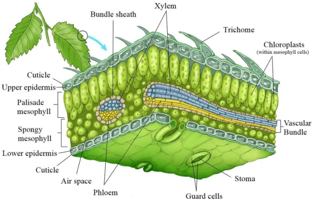
1.3 Plant Leaf Anatomy
Figure 1.3:Plant leaf anatomy. A.The petiole attaches the leaf blade to the stem. Its dimensions vary
between species.B.Adaxial vs Abaxial leaf surface. Image adapted from [33]
As to use the plant ECM for vascularization purposes, it is important to understand the anatomy of plant leaves. Although some differences can be found between plants, leaves possess basic features that are universal. Within the blade, commonly known as the leaf itself, nutrient transportation is delivered through the veins, comprised of vascular tissue. Secondary veins connect in a major vein named midrib, in a fashion that mimics the relationship between large animal vessels such as arteries and veins and their branching towards arterioles, venules and capilaries. Connecting the veins to the plant stem is the petiole, a thin stalk that can be absent in some plant species and allows for nutrients to be delivered from the plant stalk to the leaf.
1.3.1 Leaf Tissues
Leaves are highly organized structures, comprised of three different main tissues, the epidermis, the mesophyll and vascular tissue.
1.3.1.1 Epidermis
1.3. PL A N T L E A F A N ATO MY
Figure 1.4:General representation of a dicot epidermis.The epidermal tissue includes several differen-tiated cell types such as epidermal cells (most numerous and least specialized, typically less elongated in dicots), guard cells, subsidiary cells, and epidermal hairs (trichomes). Adapted from Carlson [35].
I. Cuticle
The cuticle comprises two main lipidic components; insoluble cutin/cutan and soluble waxes.
Cutinis a polyester polymer of variable size, structurally comprised of C16and C18
hydroxy and hydroxy-epoxy fatty acid monomers. Cutanis an alternative highly insol-uble polymer with an unclear molecular structure. It differs from cutin with its ability to withstand alkaline hydrolysis. Together, they form the cuticle matrix. Depending on the plant species, the matrix can be formed by cutin, cutan or both at different weight percentages.
Cuticle waxes can be epicuticular or intracuticular, depending whether they are de-posited on the surface or embedded onto the matrix. Together, they represent the plant’s main barrier to water and solute transportation across the cuticle [36].
II. Trichomes
Trichomes consist of a series of different outgrowths or appendages that come in a variety of shapes and sizes and can serve various functions. Mainly, trichomes have been found to have a protective role against insects, mostly due to its chemical secretions. As an example, bean leaves were used in the Balkan countries as a way to entrap bed bugs, being thrown on the floor and later burnt [34] [38].
1.3.1.2 Vascular Tissue
The plant vascular network allows for the transportation of nutrients and water through-out the plant, ending on the leaves. It comprises two main conductive tissues; the xylem, mainly involved in water and ions conduction from the soil, and the phloem which takes care of the transportation of water and organic molecules. This network will be taken advantage of in the present work.
I. Xylem
The xylem allows for the transportation of water and some ions under negative pressure. It can classified onto two types; the primary and the secondary xylem, depending on the stage and origin of growth. Additionally, it is comprised of tracheary elements, parenchyma cells and supporting cells, also named fibres. Regarding the tracheary elements, two types exist in the xylem; the tracheids and the vessel elements, comprised of the cell walls of dead cells arranged onto a "pipe-like"structure [39] [40] [34].
II. Phloem
1.4 . BL OOD VE S S E L A N ATOM Y
1.4 Blood Vessel Anatomy
Figure 1.5:Anatomical structure of blood vessels. a.Schematic representation of an artery wall.Smooth
muscle cells allow for it to withstand high physiological pressure. b.Structural comparison between
arteries, veins and capillaries.In veins, valves help blood return to the heart from places where gravity has a bigger effect such as the saphenouos vein. Contrary to arteries, capillaries are less resistant to pressure since they are made of a single layer of endothelial cells. Adapted from Blausen and staff [42].
Blood vessels are key parts of the peripheral vascular system including all the vessels outside of the heart, which transport blood throughout the body. It is comprised of arteries and arterioles that transport oxygenated blood from the heart, veins and venules that transport low oxygenated blood to the heart, and capillaries which are branched out vessels. Structurally, they differ slightly, with arteries having thicker walls in order to withstand the high pressure pumped from the heart. However, both arteries and veins possess a wall composed of three tissue layers; the tunica intima (thinnest layer, comprised of a single layer of endothelium supported by a subendothelial one), thetunica media(thickest layer, contains smooth muscle cells, elastic fibers and connective tissue arranged in a circular fashion) and thetunica adventia
1.5 Tissue decellularization
Figure 1.6:Advantages ofin vitrorecellularization when compared to other techniques. Decellular-ization helps reduce the risk of patient immune rejection since it can be seeded with autologous cells.
The usage of anin vitrorecellularization technique prior to implantation has also been known to
reduce the risk of complications such as thrombus formation and calcifications with the added bonus
of inducing the recruitment of progenitor cellsin vivo. Image adapted from Moroniet al.[44]
Tissue decellularization aims for the isolation of the components of the ECM while keep-ing their structural integrity, through the removal of the tissue’s inherent cells. The efficacy of the decellularization process can be assessed through different techniques such as histological staining with nuclei markers like DAPI, hematoxylin and eosin and the quantitative measure-ment of DNA [45]. These methods base themselves on the assumption that the removal of intracellular, membranous molecules and DNA are equally efficient. Also, since intracellular and membrane components possess surface antigens, the removal of these components allows for the reduction of a possible immune rejection due to xenotransplantation.
1.5. T I SSUE DE C E LL U L A R I ZAT I ON
1.5.1 Chemical Decellularization Agents
1.5.1.1 Acids and Bases
Solutions with an extreme pH value can improve the efficacy of cellular removal through the catalysis of biomolecular hydrolytic degradation.Acidssuch as per-acetic have been used in order to remove residual nucleic acids where they have been found to solubilize cytoplas-matic components with no relevant structural disturbance on the ECM. This happens because even though collagen is partially removed, the sulfated GAGs are generally not affected [46]. However, since a balance between the removal of structural protein such as collagen and the removal of other components needs to occur, it is important to optimize both the concentra-tion and exposure time to such agents.
Basesare commonly used for sample processing such as the removal of hair from skin
samples [47]. Commonly used bases such as ammonium hydroxide, sodium sulfide and sodium hydroxide work by denaturing DNA. However, since they remove important growth factors and highly decrease the mechanical properties of the ECM through the disruption of collagen crosslinks, they are a more disruptive method than acids [48].
1.5.1.2 Detergents
Detergents are effective decellularization agents that work by solubilizing cell membranes and dissociating DNA from proteins. However, their common use in protein extraction procedures infers that they will also be disrupted from the ECM, thus having a negative effect on its structural integrity. This con can be managed by lowering both the concentration and exposure time as well as combining detergents with different agents.
I. Ionic Detergents
Figure 1.7:Chemical structure of SDS.The combination of its hydrocarbon tail with a terminal polar group gives this detergent its amphiphilic properties.
achieve an adequate cell removal in animal tissue while retaining proteins such as glyco-proteins and collagens as well as retaining fiber orientation, making a huge difference regarding decellularization efficiency when compared with other agents. However, it is associated with a high GAG and growth factor removal and some structural disruption. Triton X-200 has a greater structural disruption when compared to SDS, though it can only effectively work on thinner tissues, being more commonly used as a final agent [45].
II. Non-Ionic Detergents
Figure 1.8:Chemical structure of Triton X-100.It is comprised of a hydrophilic polyethylene oxide chain and an aromatic hydrocarbon lipophilic group.
Non-ionic detergents are mainly used when it is pivotal to maintain as much of the structural protein integrity and enzyme activity as possible. They work by disrupting DNA-protein, lipid-lipid and lipid protein and, to a lesser extent, protein-protein interactions. Nonetheless, this lowers the efficiency of the process. Practical uses include tissue de-lipidation and the removal of cellular residues as a last step for tissues such as valve conduits [50].
In this category of detergents, Triton X-100 stands out in preference for decellulariza-tion procedures, due to its low structural disrupdecellulariza-tion and high GAG removal [51].
III. Zwitterionic Detergents
1.5. T I SSUE DE C E LL U L A R I ZAT I ON
1.5.1.3 Alcohols
Alcohols are mainly used as dehydrating and lysing agents, since, when permeabilized, their hydroxyl groups can diffuse into the cell, replacing the intracellular water thus lysis the cell by a process of dehydration [57]. Oxidized phospholipids are proinflammatory and proatherogenic agents which can contribute to prosthesis calcification in valves and conduits [58]. Alcohols help fix this issues since they are known lipid dissolvers. However, alcohols such as ethanol and methanol can precipitate proteins and damage the ECM structure by altering the collagen structure through crosslinking [59].
1.5.1.4 Chelators
EDTA and EGTA bind divalent metal cations, mainly Ca2+and Mg2+, helping with the cellular dissociation from ECM proteins. As a result, they are particularly used in combination with trypsin and detergents in order to ensure a maximum cellular removal [48] [57] [60].
1.5.2 Enzymatic Methods
Enzymes are highly specific agents for the removal of cell residues and unwanted ECM components when accompanied by other methods. Nonetheless, special care must be held in order to remove enzyme residues which can hinder recellularization or induce an adverse immune response.
Examples used in decellularization protocols include endonucleases (eg. DNase, RNase), proteases (eg. trypsin, collagenase) and esterases (eg. phospholipase A2) which work in dif-ferent ways. DNase and RNase catalyse the hydrolysis of the interior bonds of the nucleotide chains, while exonucleases catalyse the "exterior"terminal bonds, leading to the degradation of DNA or RNA. As such, they are mainly used as an additive to detergents in order to help remove residual DNA [61]. Since endonucleases cleave nucleotides mid-sequence, they are thought to be more effective than exonucleases at fragmenting DNA. Also, following this logic, non-site specific endonucleases would be more effective compared to site-specific ones [45].
Trypsin(EC 3.4.21.4) is perhaps, the most used enzyme in decellularization protocols. It
Other enzymes used include collagenase, dispase, thermolysin and lipase, which vary in structural disruption properties.
1.5.3 Physical Agents
1.5.3.1 Freeze–thaw cycles
Multiple freeze-thaw cycles have been shown to effectively lyse cells within tissues. How-ever, its intracellular and membranous content are not eliminated unless they are processed afterwards [65] [66]. Freeze-thaw also produces minor disruptions on the ECM structure, with no significant alterations on its mechanical properties [67].
1.5.3.2 Agitation and Immersion
Perhaps the most commonly used techniques for tissue decellularization, protocols re-garding the immersion of tissue in a solution with mechanical agitation have been published for different tissues such as the bladder [60], trachea [68], cartilage [69], dermis [48], and heart valves [70]. This technique allows for endless combinations of conditions which can be adapted to different tissues. For example, thin tissues such as the urinary bladder can be decellularized over a short period of time of a couple of hours of exposure to peracetic acid, when used a relatively aggressive agitation [71]. On the other hand, denser tissues such as the trachea or dermis require a longer exposure time and a combination of different solutions of alcohols, enzymes and/or detergents.
1.5.3.3 Perfusion
The process of perfusion decellularization consists on the usage of pressure gradients though the vascular system of the tissue or organ in order to improve the efficiency of the chemical decellularizing agents and facilitate the elimination of cellular debris, making it particularly useful for hollow tissues such as blood vessels.
Though used in tissues, the work of Wainwrightet alhas demonstrated the viability of perfusion based methods in the decellularization of porcine heart. For this, a retrograde coronary perfusion tactic was used, requiring the usage of trypsin and detergents, in cycles as well as a progressive increase in pressure [72].
1.5. T I SSUE DE C E LL U L A R I ZAT I ON
used in order to ensure a maximum removal of cellular content, as used by Wagneret al[74] in lungs.
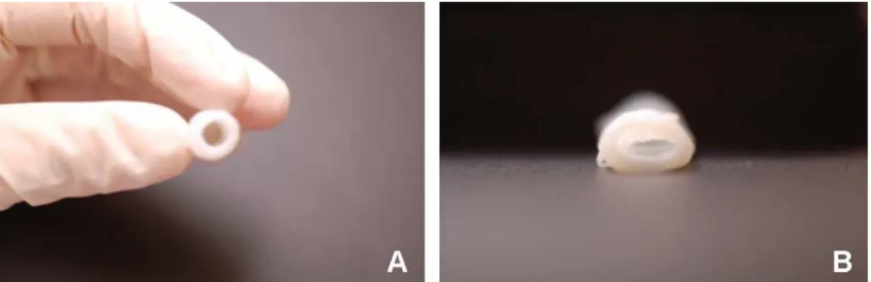
Figure 1.9:Decellularized human umbilical vein. a.Tissue decellularized through luminal perfusion.
b.Tissue decellularized through agitation. Contrary to perfusion, some loss of rigidity is noticeable.
Work and image published by Montoyaet al.[73].
1.5.4 State of the art
1.5.4.1 Decellularization of cardiovascular components
Arteries have long been decellularized successfully. In 2003, Uchimuraet al.have effec-tively decellularized porcine carotid artery and rat aorta using a 1g/mL PEG solution and DNase and re-seeded with rat vascular endothelial cells with a seemingly good conservation of mechanical properties [75].
Also in 2003, Dahlet al.’s work on porcine arteries has tested three decellularization methods. The one consisting of a two-step process presented the best results in terms of cellular content and structural properties, with a maximum stress pressure lowering from 6.6 ±1.7 MPa for native arteries to 2.1±0.7 MPa for the decellularized version. Step one
consisted of a solution blend of 8mM CHAPS, 1M NaCl and 25 mM EDTA in constant agitation for a period of 11h. Step two swapped the zwitterionic detergent with an anionic one, SDS at a 1.8mM concentration for the same period of time. Both steps were performed in agitation in a 10% CO2environment at a temperature of 37◦C. The scaffold was later rinsed with PBS and seeded with PKH-26-labeled porcine vascular SMCs, showcasing no obvious cytotoxicity [76]. The protocol has since been repeated by several groups such as Quintet al.
[77] in 2011 who used a porcine carotid artery which was then implanted as an end-to-end graft and recellularizedin vivo, showcasing good patency and collagen retention.
by nuclease digestion. Both methods showcased little alteration on collagen content and mechanical properties with a preserved function.
Likewise, veins have suffered decellularization through several protocols, though not as popular as arteries. An example is a protocol used by Schaneret al.[80] in 2004 where human greater saphenous veins were decellularized through immersion with different SDS concen-trations of 0.01, 0.025, 0.05 and 0.075% , the later having the best results. The resulting scaffolds possessed a 94% decellularization yield with similarin vitroburst strenght and colla-gen content to native veins, functioning properly with no dilation or rupture after 2 weeks of perfusion.
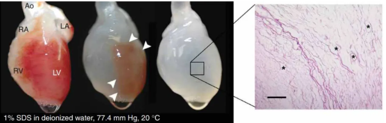
Figure 1.10:Decellularization process on rat heart.After 12h the heart becomes more translucent as the cellular material is removed through the right ventricle. HE staining showcases the conservation of large vasculature conduits (black asterisks). Ao, aorta; LA, left atrium; LV, left ventricle; RA, right
atrium; RV, right ventricle. From Ottet al.[81]
Perfusion is a common technique especially in regard whole-organ decellularization. A great example was published in 2008 by Ottet al.[81] where rat hearts were decellularized by coronary perfusion of 1% SDS for 12h followed 1% Triton-X-100 for 30 minutes and an antibiotic solution for 124h. The scaffold was later reseeded with rat aortic endothelial cells with either intramural injection or perfusion into the vascular conduits, resulting in a bio-compatible matrix with a perfusable vascular tree capable of being implanted.
1.5.4.2 Plant decellularization and blood vessels
Being an easily available and highly vascularized system, with a functional architecture similar to animal tissues, plant leaves are a promising ethically sustainable and environmen-tally friendly material regarding their possible use as a pre-vascularized scaffold for tissue engineering applications. Moreover, their high hidrophilicity allow for cellular expansion through long periods of time in a way that conforms to the microstructure of the plant’s framework.
1.5. T I SSUE DE C E LL U L A R I ZAT I ON
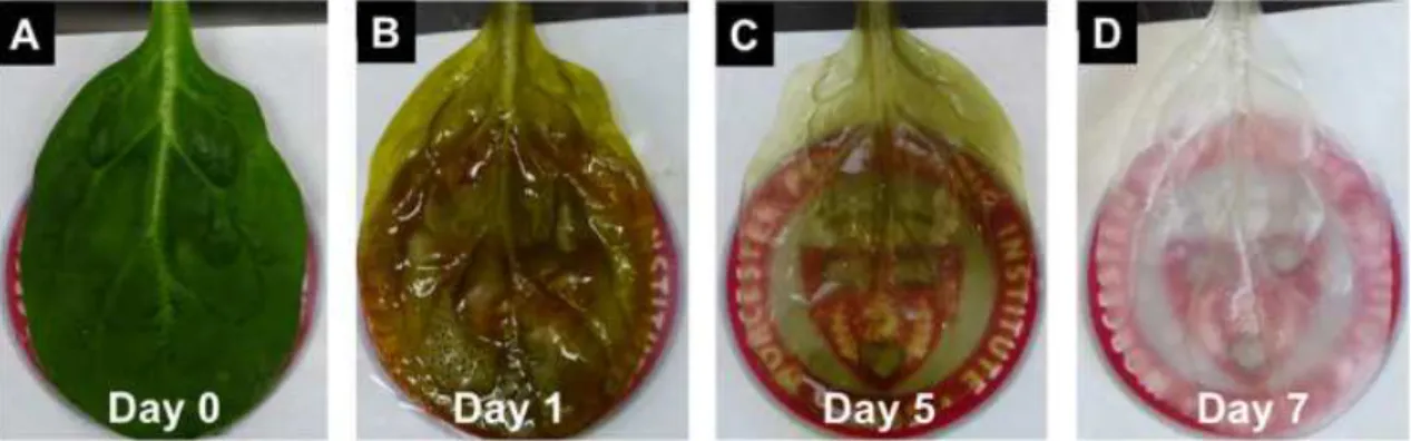
Figure 1.11: Decellularization timelapse in spinach leaf.After 5 days the leaf reaches a translucent
green hue which is removed when a 10% sodium chlorite solution is added (imaged.). Work and image
published by Gershlakaet al.[82].
the properties of native hypanthium (floral tissue) of apples. Firsty, in 2014, the scaffold was successfully seeded with NIH3T3 fibroblasts, mouse C2C12 muscle myoblasts and human HeLa epithelial cells, remaining viable for up to 12 weeks [83]. Its ability to work as an implantable cellulose scaffold was later confirmed in 2018. The developed scaffold showcased an immune response that gradually disappeared as of the 8th week post implantation, with an active migration of fibroblasts and blood vessel formation [84].
However, the usage of plant decellularization techniques as a way to build vascularization was first shown by Gershlakaet al.In their article published in 2017, spinach leaves were treated with hexanes and later decellularized using a 10% SDS solution perfused through can-nulas for 5 days after which a solution mix of 0.1% Triton-X-100 and 10% sodium chlorite bleach was perfused for an aditional 48h, both at a constant pressure of 152 mmHg. Post decel-lularization, the scaffolds retained patency and were capable of transporting microparticles. Later, they were reseeded with human mesenchymal stem cells and human pluripotent stem cell derived cardiomyocytes which adhered to the outer surfaces of the plant leaf. Particularly cardiomyocytes showcased their contractile and calcium handling properties over the course of 21 days [82].
1.6 Electrospinning
Electrospinning is a common technique where a highly viscous synthetic or natural poly-meric solution is made into solid fibres, having a diameter between a few micrometers and a few nanometers, with the help of an electric field. The solution emerges at the end of a blunt needle or capillary tube to which a high voltage (usually between 10 and 30 kV) is applied. The interplay between surface tension and coulombic repulsion between like charges leads to the formation of a conical shape commonly named Taylor cone from which a solution jet emerges. The solution whips and elongates as it travels towards the collector due to the electrostatic repulsions between the surface charges, the Couloumbic force exerted by the external electrical field and solvent evaporation. [85] [86].
Figure 1.12:Basic electrospinning aparatus.The electrospinning technique allows for the production of non-woven nanofibers using an electric force to draw charged polymeric threads towards a moving
or static collector. SEM image represents non-oriented fibres of PVP. Adapted from Liet al.[86].
These fibres can be aligned with the rotation of a cylindrical collector at a high speed since when the linear speed of the rotating cylinder matches that of the evaporated depositions, the fibres align in a circumferential manner. Thus, higher speeds will result at a tighter alignment whereas lower speeds will decrease the alignment.
1.6. E L E CT RO SPI N N I N G
and a grounded metallic collector. Also, optimization can be achieved through the manipula-tion of several different parameters. These include solumanipula-tion properties such as conductivity, viscosity and surface tension; environmental parameters such as air humidity, velocity and the temperature of the solution and process parameters such as the electric potential, flow rate, needle-collector distance, collector composition and its geometry [87].
The flexibility of the electrospinining technique allows it to be used with several different polymers, as long as they can be charged and have the necessary viscosity to be elongated towards the collector. In the present work two polymers will be used, PCL and PEO.
1.6.1 Polycaprolactone
PCL is a hydrophobic, semi-crystalline polymer, belonging to the poly(α-hydroxy) ester family that can be prepared through two different paths; the ring-opening polymerization of the cyclic monomerǫ-caprolactone by a catalyst such as stannous octoate and the polyconden-sation of 6-hydroxyhexanoic acid [88]. Due to its biocompatibility and easy processing (low melting point and solubility in a wide range of organic solvents and miscibility with different polymers), PCL has turned into one of the most commonly used polymers for biomedical purposes [89]. In fact, PCL can be mixed with other polymers as a way to improve its char-acteristics, such as adhesion and stress crack resistance [90] and is known to be soluble in chloroform, carbon tetrachloride, benzene, toluene and dichloromethane at room tempera-ture with a low solubility in acetone and acetonitrile and total insolubility in alcohol [91].
Figure 1.13: Chemical structure of PCL. Resulting from the ring opening polymerization of ǫ -caprolactone, PCL is a biodegradable polyether widely used in tissue engineering due to its mechanical properties.
loss. Once most amorphous regions are degraded, the actual hydrolytic degradation of the crystalline begins [93].
1.6.1.1 State of the art: polycaprolactone in blood vessel engineering
Throughout the last 15 years, several articles have been published regarding the usage of PCL in blood vessel engineering.
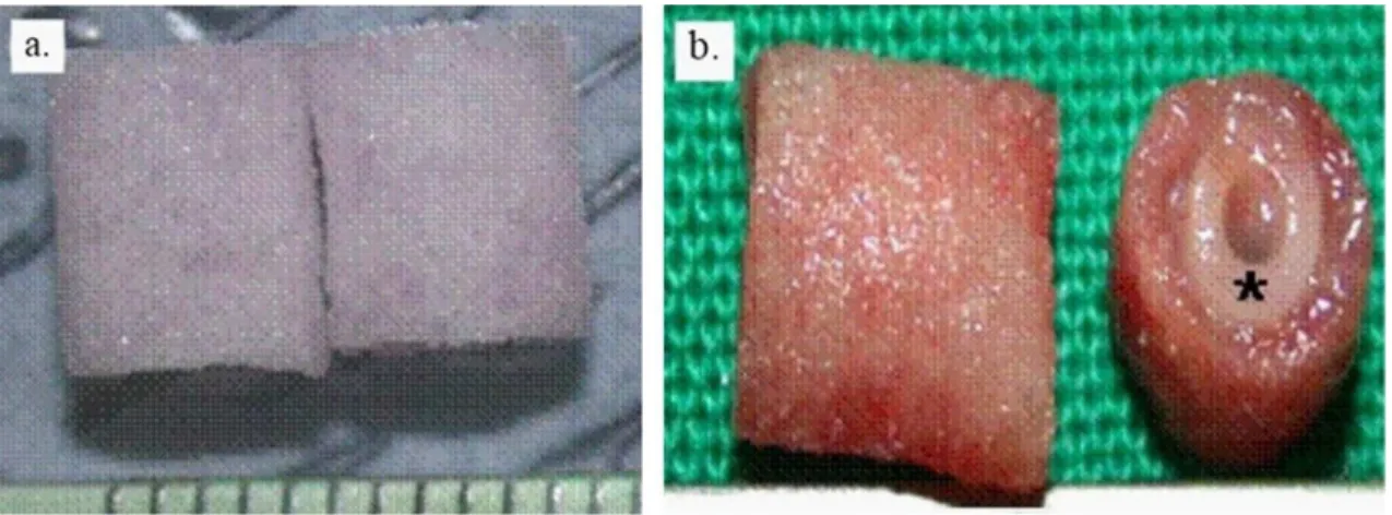
In 2004, Jeonget al.[94] have fabricated tubular, elastic and biodegradable scaffolds from poly(l-lactide-co-ǫ-caprolactone)(PLCL) at a 50:50 ratio which were seeded with smooth muscle cells and implanted onto mice, displaying an "excellent tissue compatibility". The scaffolds have also displayed a high elasticity, being able to withstand an extension of up to 210% with a 97
Figure 1.14:PLCL scaffold implanted into athymic mice. a.Scaffold before implantation.b.Explanted
scaffold (black asterisk) after 8 weeks. Adapted from Jeonget al.[94]. Scale not provided.
Reaching 2005, multi-layered tubular scaffolds have been produced, such as the one made by Vazet al.[95] containing an inner layer of PCL and an outer layer of a stiff polymer named poly-lactic acid (PLA), fabricated layer by layer through electrospinning. The resulting struc-ture contained micro and nanofibers interconnected by pores of an average 10µm, mimicking the natural anatomy of the blood vessel. Their mechanical properties were found to be ac-ceptable, with a composite Young’s modulus much higher than that of simple PCL.
In 2008, Notteletet al.[96] produced electrospun PCL scaffolds averaging between 500-2500 nm diameter, creating 2 and 4 mm vessels. They showcased promising mechanical properties, with tensile stress values up to 7.4 MPa, much higher than the ones for native human blood vessels (1.4 MPa).
1.6. E L E CT RO SPI N N I N G
integrity and patency when exposed to physiological conditions. Also, the matrices were found to resist the adherence of platelets when exposed to blood.
However, in 2012, Valenceet al.’s long-termin vivostudy using electrospun PCL tubes in rat aorta for a period 18 months, has raised questions regarding the viability of PCL as an implantable scaffold. Though results seemed promising by the 6 month mark, with a rapid colonization of fibroblasts and macrophages and wide neovascularization, after 6 months, tissue regeneration began to regress with an increase of calcification, a reduced vascularization and both macrophage and fibroblast count and a cell regression in the hyperplasia of thetunica intima[98], a result that contradicts the previously published by Pektoket al.in 2008 [99].
Since then, PCL has been mainly used in conjunction with other materials such as collagen [100], gelatin [101] and alginate [102] [103].
1.6.2 Polyethylene Oxide
PEO (CH2CH2O)nis a polyether compound best known for its hydrophilic properties to
which terminal hydroxyl groups contribute. However, its ether oxygens along the backbone must be considered in order to understand polymer/water interactions [104]. It can also be named PEG, which is applied to a lower molar mass, suggesting a glycolic chemical nature due to the significant contributions from the terminal hydroxyl groups [105].
Figure 1.15:Chemical structure of PEO.Also known as PEG depending on its molecular weight, PEO is a hydrophilic polyether polymer with a high solubility in water which is largely used for various industries and applicabilities.
1.7 Work plan and Objectives
The work presented concerns the development of a vascular network by taking advantage of the already existing transport complex characteristic of plant leaves. In order to achieve it, a decellularization technique will be used, a process that will be optimized throughout the presented work. Plant decellularization is a cheap and practical way of using the leaf’s vasculature system without an immune response since the nuclear content is removed and both materials and reagents are easily available in large quantities.
Several approaches have been used in the past for the resolving of the problem of tissue vascularization. Thus, we have found important to compare this bio-approach to already known materials. Because of its well-known and proved behaviour, we have decided to test PCL as the main synthetic polymer. Its performance will be upgraded with the conjunction with PEO, due to its easiness to dissolve in water and low cytotoxicity, as to produce pores that can serve as aids for cellular migration.
The work at hand will aim to reach several objectives. Firstly, "Papo de Rola"common beanPhaseolus VulgarisL. (CB), New Zealand spinachTetragonia tetragonioides(Pallas) Kuntze (NZ), Winter Giant (WGS) and Viroflay (VS) spinach Spinacea oleracea L., Rumex crispus
C
h
a
p
t
e
r
2
Mater ia l s a n d Meth o d s
2.1 Plant Leaf Decellularization
2.1.1 Plant germination and growth
2.1.1.1 Plant germination
New Zealand spinach (Tetragonia tetragonioides (Pallas) Kuntze), Winter giant (Spinacia oleraceaL.) and common "papo de rola"bean (Phaseolus vulgarisL.) seeds were both incubated and not incubated at 4◦
C for 7 days pior to germination in order to optimize a decrease in latency periods. Afterwards, the seeds were placed onto a Petri dish coated with humid paper along with the ones of common sowhistle (Sonchus oleraceusL.), and curly dockRumex crispus
L. and left to germinate.
2.1.1.2 Plant growth
After germination the above mentioned plants were transferred onto vases with a potsize 14 x 14.6 cm with a mixture of 1:1:1 soil, peat and sand and divided into 3 growth conditions; Plant Chambers, Lumigrow and Temperature-controlled conditions.
Plant Chambers: A FitoClima (AraLab Fitoclima 700 EDTU) plant chamber was set with
a 12h/12h photoperiod (night/day) and a temperature amplitude of 17-22◦
C at 55-60% relative humidity.
Lumigrow: A room was illuminated with a Lumigrow Pro 325™light set with a spectral
nm) and set with a 12h/12h photoperiod (night/day) and a temperature amplitude of 17-22◦ C. The relative humidity was controlled at an amplitude of 50-60%.
Temperature-controlled conditions: Some of the remaining seedlings were placed onto
a temperature controlled room set between 24-28◦ C.
All plants were watered with 50 mL of nutritive solution twice a month and regular water twice a week. Their growth was monitored in terms of leaf number and height and leaf dimensions measured 3 times a week.
2.1.1.3 Nutritive solutions
All solutions are adaptations from the ones published by D.I Arnon and D.R Hoagland [108] [109].
1M Macro Solution: 500 mL of solution were prepared with 100 mM KNO3 (Merk),
30 mM Ca(NO3)2.4H2O (Sigma-Aldrich), 20 mM anhydrous MgSO4 (Fluka) and 20 mM NaH2PO4(Fluka).
A4 100x Solution: 25 mL were prepared with 9 mM H3BO3(Merk), 2 mM MnCl2.4H2O
(Riedel de Haën), 0.4 mM ZnSO4.7H2O (Merk) and 10 mM Fe(III)-EDTA (Sigma-Aldrich).
B6 10 000x Solution: 10 mL were prepared with 3 mM of CoSO4.7H2O (Merk), 0.7 mM
(NH4)6Mo7O24.4H2O (Riedel de Haën), 0.5 mM K2Cr2O7(Merk), 2 mM NH4VO3(Merk), 5 mM CuSO4.5H2O (Merk) and 2 mM NiSO4.7H2O (Fluka).
The final nutritive solution was prepared with a ratio of 100 mL Macro + 1 mL A4 + 100
µL B6.
2.1.2 Plant leaf conservation and transportation
2.1.2.1 Conservation assays
Five solutions were tested in terms of conservation potential for native leaves incubated at 4◦
C.
Adapted Euro-Collins: The prepared solution was adapted from the protocol published
by Yamazaki et al. [110]. A 4x stock solution was prepared with 960 mM of D-glucose (Ducheta), 3 mM Mg.SO4.6H2O (Fluka), 40 mM KHCO3(Merk), 116 mM K2HPO4(Merk), 117 mM KH2PO4 (Merk), 168 mM C2H3KO2 (Merk), 40 mM NaCl (Panreac) and 20 mM KCl (Sigma-Aldrich). The pH was set to 7.4 by using HCl 1M and the solution sterilized .
PEG 10% + Glucose: A 250 mL solution was prepared by using 2.5g of PEG 4000 (Fluka)
and 10.8g D-Glucose (Ducheta) for a final glucose concentration of 240 mM and later sterilized by autoclave.
2.1. PL A N T LE A F DE C E L L UL A R I ZAT I O N
Bean leaves were divided in sets of 4 (2 fully developed and 2 smaller, younger leaves) and placed in bags, each with 50 mL of the prepared solutions and left in the dark at 4◦
C. The conservation state of the leaves was visually monitored for 11 days.
2.1.2.2 Pigment Quantification
Sample weigh-in: The previously tested leaves, along with regular ones were cut into
sections (while avoiding nerves), excess water removed with a paper towel and weighed.
Determination of water content: The weighed samples were divided onto two groups,
one of which was incubated at 60◦
C. After 2 weeks, the samples were weighed again.
Pigment quantification protocol: Each sample was macerated on an iced mortar and
placed onto an eppendorf tube where they were once more macerated with cold 90% acetone (Sigma-Aldrich) at a ratio of 4.5 mL per gram of fresh material. 1 mL of the supernatant was transferred onto another tube and centrifuged (Eppendorf Centrifuge 5415 R) for 10 min at 12 000×gand 4◦C. Once again, the supernatant was removed and placed onto another
tube of which the absorvance was measured at 663, 645 and 470 nm in a Shimadzu UV-1603 UV-Vis spectrometer.
The formulas used were adapted Ramalhoet al.[111] and Lichtenthaler [112] and corrected toµg.mg−1
.cm−2 .
Chla= 12.25Abs663−2.79Abs645 (2.1)
Chlb= 21.50Abs645−5.10Abs663 (2.2)
Chl(a+b) = 7.15Abs663+ 18.71Abs645 (2.3)
Car(x+c) = 1000Abs470−1.82Chla−85.02Chlb
99 (2.4)
2.1.2.3 Plant transportation
After being grown, the plants were harvested for their leaves which were transported in bags containing a 15% PEG 4000 solution at a constant temperature of 4◦
2.1.3 Plant leaf decellularization
All plant leaves tested were treated before the decellularization process as to remove cuticular waxes. In order to achieve it, a p.a solution of chloroform or acetone was used in repetition cycles of 10 or 15s and its effects on the leave’s structural integrity assessed.
In all decellularization protocols, the samples were immersed in destilled water for a period of 7-15 days and the water was changed every other day.
2.1.3.1 Immersion protocols
Leaves were placed onto a glass crystalizer with 100 mL of decellularization solution and agitated at a rate of 100 rpm until transparency.
Conditions tested:
Table 2.1:Immersion decellularization conditions for SDS and Triton X-100.All samples were im-mersed in a SDS + Triton X-100 solution with varying concentrations. Total time displays the amount of days passed until the end of the assay, let it be for reaching full transparency or problems such as microbial contamination.
Plant
SDS Triton X-100 Total time Condition
(%) (%) (days)
VS & CB
1 5 34 PD1
5 1 72 PD2
1 10 72 PD3
VS 3 3 70-71 PD4
5 3 75 PD5
CB 5 3 68-73 PD6
NZ
5 5 63-76 PD7
5 1 76 PD8
5 3 50 PD9
WGS
1 5 62 PD10
5 3 62 PD11
10 - 62 PD12
RC 5 1 42 PD13
2.1. PL A N T LE A F DE C E L L UL A R I ZAT I O N
Table 2.2: Mixed immersion decellularization conditions. Under parenthesis is represented the amount of days passed with that particular concentration. Concentrations with the same days dis-played represent a mixed solution of those compounds.
Plant SDS Triton X-100 NaCl Bleach Step Time Condition
(%) (%) (M) (%) (days)
VS
5 0.5 - - 1 18
PD15
- - - 0.5 2 6
5 - - - 1 16
PD16
- 3 - 0.5 2 6
CB - 3 0.2 - - 19 PD17
1 3 0.2 - - 64 PD18
RC
- 5 0.2 - - 19 PD19
- 1 0.2 - - 45 PD20
5 - 0.2 - - 19 PD21
1 5 0.2 - - 19 PD22
2 3 0.2 - - 45 PD23
Table 2.3:Detergent-free decellularization conditions.Condition 24 is seeded onto an acetate buffer
made with 100 mM C2H3NaO2(Sigma-Aldrich) and 100 mM CH3COOH (Sigma-Aldrich) per 100
mL of solution. Condition 25 is seeded onto a potassium bicarbonate buffer built with 84 mM KHCO3
(Sigma-Aldrich) per 100 mL of solution.
Plant Ethanol pH Bleach Total Time Condition
(%) (%) (days)
VS
4 4 - 7 PD24
4 8.5 - 7 PD25
- - 0.5 7 PD26
2.1.3.2 Perfusion protocols
Two perfusion methods were tested where pressure came from either gravity or a pump.
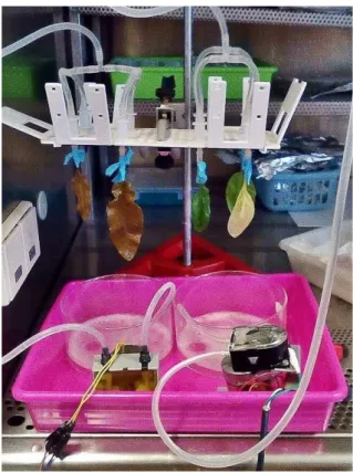
Gravity-based perfusion:Leaves were perfused through a blunt needle along the petiole
Figure 2.1:Gravity-based decellularization setup.The chosen decellularization solution is perfused through plastic tubes onto blunt needle tips towards the leaves, which are also immersed onto the same decellularization solution inside glass tins. Setup built at FCT-UNL.
Pump-based perfusion:Likewise, the leaves were immersed and set onto the support in a
similar fashion. A peristaltic pump circulates the decellularization solution from the tin to the leaves. A sensor was placed underneath the pump pressure converted to a voltage value, read by a multimeter. The sensor setup used was built by Ana Pádua [113] and allowed for the calculation of the pressure exerted onto the leaves by a simple calibration curve between pressure and voltage. The pressure was found to oscillate slightly along the process between 81 and 100 mmHg.
2.1.4 Plant histology
2.1. PL A N T LE A F DE C E L L UL A R I ZAT I O N
2.1.5 Optimization of the decellularized material
2.1.5.1 Gelatin coatings
Epichlorohydrin (ECH) treatment:Decellularized leaves were cut onto circular sections,
10 mm in diameter. The samples were immersed in 10mM ECH (Sigma-Aldrich) solution containing 67mM NaOH and incubated for 2h at 50◦
C. They were then removed from the solution and rinsed with distilled water until neutral. The used protocol was retrieved from Zenget al.[115].
Gelatin solutions:Bovine skin type B (Sigma-Aldrich) and porcine skin (Sigma-Aldrich)
gelatin solutions were produced at a concentration of 0.5, 2, 4 and 5% in water and sterilized by autoclave at 120◦
C. 500µL of the 0.5, 2 and 5% solutions were added to the scaffolds placed on 24-well microplaques and left overnight. The solutions were later removed and washed with PBS and seeded according to the protocol shown in section 2.3.1.
2.1.6 Mechanical Tests
Plant scaffolds were cut into sections and their dimensions measured. The samples were then mounted in a tensile testing machine from Rheometric Scientific using a load cell of 20 N. Load was applied at a rate of 1 mm/min with a clamps separation of 2 mm.
2.1.7 Scaffold DNA assessment
2.1.7.1 DNA extraction and quantification
Samples of regular and decellularized CB, VS and NZ were cut onto approximately 0.3g aliquots while avoiding the petiole and vein area, frozen with liquid nitrogen, throughly macerated and placed onto 2 mL microcentrifuge tubes. The following protocol was adapted from Keb-Llaneset al.[116].
Extraction Buffer A (EBA): 50 mL were prepared with the following concentrations:
100 mM Tris-HCl buffer (pH 8.0), 20 mM EDTA (Sigma-Aldrich), 1.4 M NaCl (Panreac), 4% (w/v) polyvinylpyrrolidone (PVP) (Merk) and 0.1 % (w/v) ascorbic acid and autoclaved. 2% (w/v) hexadecyltrimethylammonium bromide (CTAB) (Sigma-Aldrich) and 30µL ofβ -mercaptoethanol (Sigma-Aldrich) were added the day of the experiment.
Extraction Buffer B (EBB):50 mL were prepared with the following concentrations: 100
mM Tris-HCl buffer (pH 8.0), 50 mM EDTA (Sigma-Aldrich) and 100 mM NaCl (Panreac) and autoclaved. 30µL ofβ-mercaptoethanol were added the day of the experiment.
TE Buffer:100 mL were prepared using 10 mM of Tris-HCl (pH 8.0) buffer and 1 mM
Firstly, 300µL of EBA, 900µL of EBB and 100µL of SDS 20% (Sigma-Aldrich) were added to the tubes containing the samples and further ground with a tube pestle. The tubes were spun on vortex for 2 min and incubated at 65◦
C for 15 min. Afterwards, they were placed on ice and 410µL of cold 5 M potassium acetate solution (Merk) were added. The tubes were mixed by inversion and placed on ice for 5 min, after which they were centrifuged at 16 000
×gfor 15 min in a refrigerated (4◦C) Eppendorf 5415R centrifuge. 1 mL of the supernatant
were then transferred to a new microcentrifuge tube, added 540µL of ice cold isopropanol (Riedel del Haën) and incubated in ice for 40 min. The tubes were again centrifuged at 16 000×gfor 15 min and the pellet washed with 500µL of 70% ethanol (Scharliau). The dry
pellet was again ressuspended using 600µL of TE and 500µof ice cold isopropanol and again centrifuged, discarded the supernatant washed with ethanol and left to dry. Once dried, the pellets of regular CB and VS were resuspended with 50µL TE and the remaining ones with 30µL.
DNA quantification was performed using a NanoDrop ND-2000C spectrofotometer.
2.1.7.2 Agarose Gel
The extracted samples were loaded onto a 1 % (w/v) agarose (Seakem) gel in 1x TAE (Tris-Acetate-EDTA buffer) added with Gel Red Nucleic Gel Stain 10 000×, using 5µL of sample
diluted onto 5µL of loading solution (Sigma-Aldrich). A Gene RulerT M DNA Ladder Mix ready to use marker was used.