Universidade do Minho
Escola de Engenharia
Maria Manuel Carvalho de Freitas Martins
Online Control of a Mobility Assistance
Smart walker
Dissertação de Mestrado
Ciclo de Estudos Integrados Conducentes ao
Grau de Mestre em Engenharia Biomédica
Trabalho realizado sob a orientação de
Professora Cristina P. Santos
Universidade do Minho
Professor Anselmo Frizera Neto
DECLARAÇÃO
Nome: Maria Manuel Carvalho de Freitas Martins
Endereço electrónico: [email protected] Telefone: +351 965774086 Número do Bilhete de Identidade: 13460809
Título dissertação: Online Control of a Mobility Assistance Smart Walker Ano de conclusão: 2011
Orientador: Professora Cristina P. Santos Co-Orientador: Professor Anselmo Frizera Neto
Designação do Mestrado: Ciclo de Estudos Integrados Conducentes ao Grau de Mestre em Engenharia Biomédica
Área de Especialização: Electrónica Médica Escola: de Engenharia
Departamento: de Electrónica Industrial
DE ACORDO COM A LEGISLAÇÃO EM VIGOR, NÃO É PERMITIDA A REPRODUÇÃO DE QUALQUER PARTE DESTA TESE/TRABALHO.
Guimarães, ____/____/________
iii
Acknowledgments
First I want to thank my parents. Without their love, affection and all the support that they always gave to me in these past years, I may not be where I am now. In addition, for all their support, they always made available the necessary for my academic success, always instilling in me a great sense of responsibility. For these reasons I am very proud of them and hope never to have them disappointed.
Thank to my mentors, Cristina Santos e Anselmo Frizera.
Professor Cristina thank you for your unconditional support, knowloedge, experience and friendship. Thank you for all the strength and courage that you gave me so that everything went in the best way possible. Thanks to your constant encouragement, I could overcome all my problems and challenges.
Thank you Anselmo for the support and especially for allowing me to participate in this project and perform it in the best way. Even far we can be a good team and develop a great work.
To my collegues from the CSIC group and ASBG for their friendship and help. I want to thank especially Eloy and Miguel that always shown willingness to help me in what I needed, always contributing with their good mood and knowlodge to help me to do a good work. Thank you also for the tremendous support and patience. And all the volunteers that performed the experiences.
To Ramón for your great knowldge and share of experience throughout this work.
To professor Paulo Carvalhal and Manuel João for the willigness, help and advices that you shared with me.
To my friends and brother who always accompanied me and lived with me this past year. Thanks for your support and patience and all the strenght that you gave me during this work.
To Sara Tribuzi for her enormous help in the formatting of this thesis.
Thank you very much to everyone.
v
Agradecimentos
As minhas primeiras palavras de agradecimento vão para os meus pais. Sem o amor, carinho e todo o apoio que sempre me deram ao longo dos anos possivelmente não estaria onde estou. Além, de todo o seu apoio, sempre me disponibilizaram o necessário para que o meu aproveitamento escolar dependesse apenas de mim, incutindo-me sempre um grande sentido de responsabilidade. Por estas razões tenho muito orgulho neles e espero nunca os ter decepcionado. Aos meus grandes orientadores, Cristina Santos e Anselmo Frizera. Professora Cristina obrigada pelo seu apoio incondicional, conhecimento, experiência e grande amizade. Obrigada por toda a força que me transmitiu e ânimo para que tudo corresse da melhor forma. Graças aos seus constantes incentivos, mensagens de coragem, consegui ultrapassar as minhas dificuldades e superar os desafios.
Anselmo obrigado pelo apoio e força e principalmente por permitir que entrasse neste projecto, e que o realizasse da melhor forma. Mesmo longe conseguimos ser uma boa equipa e desenvolver um grande trabalho.
Aos meus colegas de grupo do CSIC e do ASBG pelo seu companheirismo e ajuda. Queria agradecer especialmente ao Eloy e ao Miguel que sempre mostraram disponibilidade para me ajudar no que fosse preciso, contribuindo sempre com a sua boa disposição para a obtenção de um bom trabalho. Obrigado também pelo grande apoio e paciência. E claro a todos os voluntários que me participaram nas experiências.
Ao Ramón Ceres pelo seu grande conhecimento e partilha de experiência ao longo deste trabalho.
Queria também agradecer ao professor Paulo Carvalhal e professor Manuel João pela disponibilidade, ajuda e conselhos que partilharam para a realização de um bom trabalho.
Aos meus amigos e irmão que sempre me acompanharam e conviveram comigo neste último ano. Obrigado pelo apoio e paciência e por toda a força que me deram durante a realização deste trabalho. E claro à Sara Tribuzi por ter tido tanta paciência e me ter ajudado na formatação desta tese. Sem a tua ajuda isto não tinha ficado tão bonito.
“Pedras no caminho ?
vii
Abstract
This work presents the NeoASAS project that was developed at the Bioengineering Group, Consejo Superior de Investigaciones Cientificas (CSIC) in Madrid. Further, it continued with adaptations and improvements at Minho University with the Adaptive System Behavior Group (ASBG) in Guimarães, being designated by ASBGo Project.
These developments include the conceptual design, implementation and validation of Smart Walkers with a new interface approach integrated into these devices. This interface is based on a joystick and it is intended to extract the user’s movement intentions. It was designed to be user-friendly and efficient, meeting usability aspects and focused on a commercial implementation, but not being demanding at the user cognitive level. Considering the ASBGo walker, the overall assemblage, mechanical adjustments, electronics and computing have been performed.
First, a review about the mobility assistive devices is presented, specially focused on Smart Walkers. Despite the intensive research, in current literature, there are not many works providing a "point of the situation", and explaining the role that robotics can play in this domain.
Healthy users performed preliminary sets of experiments with each walker, which showed the sensibility of the joystick to extract command intentions from the user. These signals presented a higher frequency component that was attenuated by a Benedict-Bordner g-h filter, considering the NeoASAS walker and by a Butterworth circuit, considering the ASBGo walker. These methodologies offer a cancelation of the undesired components from joystick data, allowing the system to extract in real-time user’s commands. Based on this identification, an approach to the control architecture based on a fuzzy logic algorithm was developed, in order to allow the control of the walkers’ motors. In addition, a set of sensors were integrated on the walker for safety reasons: an infrared sensor to detect if the user is falling forwards; two force sensors to make sure that the user is properly grabbing the hand support; and two force sensors in the support forearms to verify if the user is with his forearms properly supported. This will make sure that the device stops when one of these situations happens.
Thus, an assistive device to provide safety and natural manoeuvrability was conceived and offers a certain degree of intelligence in assistance and decision-making. These results will be used to advance towards a commercial product with an affordable cost, but presenting high reliability and safety. The motivation is that this will contribute to improve rehabilitation purposes by promoting ambulatory daily exercises and thus extend users’ independent living.
ix
Resumo
Este trabalho apresenta o projecto NeoASAS desenvolvido no Grupo de Bioengenharia, do Consejo Superior de Investigaciones Cientificas (CSIC) em Madrid. Este teve continuidade com adaptações e melhorias na Universidade do Minho com o grupo Adaptative System Behaviour (ASBG) em Guimarães, sendo designado por projecto ASBGo.
Estes desenvolvimentos incluem o projecto concetual, implementação e validação de andarilhos inteligentes com uma nova interface integrada nestes dispositivos. Esta interface é baseada num joystick e tem como objetivo a extração de intenções de comando do utilizador, sendo intuitiva e eficiente. Atende a aspectos de usabilidade e está focada numa aplicação comercial, não sendo exigente a nível cognitivo. Considerando o andarilho ASBGo, foi realizada a construção deste, bem como, ajustes mecânicos, eletrónicos e programação.
É apresentada uma revisão sobre os dispositivos de assistência à marcha, tendo especial enfoque os andarilhos. Apesar da intensa investigação, na literatura não existem trabalhos que apresentem o ponto de situação desta área, bem como o seu papel na robótica de reabilitação.
Depois foram realizados testes com utilizadores, mostrando a sensibilidade que o joytick tem na identificação de inteções de comando do utilizador. Além disso, os sinais apresentam uma componente de alta frequência que foi atenuada, no caso do NeoASAS, com um filtro g-h Benedict-Bordner, e no caso do ASBGo, através de um filtro Butterworth implementado em hardware.
As metodologias apresentadas oferecem um cancelamento componentes indesejáveis, permitindo ao sistema a extração das intenções de comando do utilizador em tempo real. Desta forma, uma arquitetura de controlo baseada em fuzzy logic foi desenvolvida de maneira a fornecer uma assistência segura ao utilizador, através do controlo dos motores. Foram também integrados um conjunto de sensores no andarilho por razões de segurança: um sensor infravermelho para detetar a queda frontal do utilizador, dois sensores de força nos apoios de mão para detetar se o utilizador está a agarrá-los, e dois sensores de força nos suportes de antebraço para certificar que o utilizador está devidamente apoiado.
Assim, foi concebido um dispositivo que garante a segurança do utilizador e oferece um certo grau de inteligência e tomada de decisão. Estes resultados serão utilizados para a criação de um produto comercial com custo acessível, mas com alta confiabilidade. A motivação deste trabalho reflete-se na contribuição que este dispositivo terá na melhoria da reabilitação e desenvolvimento de dispositivos ambulatórios para promover exercicios diários, e melhorar a vida dos utilizadores.
xi
Table of Contents
Acknowledgments ... iii Abstract ... vii Resumo ... ix Table of Contents ... xi List of Figures ... xvList of Tables ... xxi
1. Introduction ... 1
1.1. Motivation ... 1
1.2. Context ... 1
1.3. Objectives ... 4
1.4. Results from the thesis ... 5
1.5. Structure of the thesis ... 5
2. Review and Classification of Assistive Mobility Devices ... 9
2.1. Introduction ... 9
2.2. Gait Dysfunctions ... 10
2.3. Mobility Assistive Devices ... 12
2.3.1. Mobility Training Devices ... 14
2.3.2. Self-ported Devices ... 19 2.3.3. External Devices ... 20 2.4. Walkers ... 21 2.4.1. Conventional Walkers ... 22 2.4.2. Smart Walkers ... 25 2.4.2.1. Physical Support ... 25 2.4.2.2. Sensorial assistance ... 28 2.4.2.3. Cognitive assistance ... 29 2.4.2.4. Health Monitoring ... 30
xii
2.4.2.5. Advanced Human-Machine Interface ... 30
2.5. Conclusions ... 37
3. Background and Presentation of the NeoASAS and ASBGo Projects ... 41
3.1. Introduction ... 41
3.2. Background: Project ASAS and SIOMBIOSIS ... 42
3.3. NEOASAS walker and ASBGo walker ... 44
3.3.1. Considerations about the NEOASAS and mechanical modifications ... 44
3.3.2. Considerations about the ASBGo and mechanical modifications ... 46
3.3.3. Subsystem for evaluation of user’s command intentions ... 48
3.3.3.1. Specifications of the interface ... 49
3.3.3.2. User’s gestures while guiding the Smart Walker ... 52
3.3.4. Fall and Grasp Detection – Safety considerations ... 53
3.3.5. Modular Architecture for Data Acquisition and Processing ... 53
3.3.5.1. NeoASAS Architecture ... 53
3.3.5.2. ASBGo Architecture ... 55
3.4. Conclusions ... 56
4. Validation of the Proposed Interface ... 59
4.1. Introduction ... 59
4.2. Evaluation of the signal related with the users’ command intentions in the NeoASAS and ASBGo walkers. ... 60
4.3. Joystick’s Signal Processing Architecture ... 67
4.4. Signal processing architecture of the NeoASAS walker ... 67
4.4.1. Selection and implementation of a filter strategy ... 68
4.4.1.1. Selection of the filters parameters and their optimization ... 89
4.4.1.1.1. Conclusion of the Filter Strategy ... 102
4.5. Signal processing architecture of the ASBGo walker ... 102
xiii
4.5.2. Z-signal Circuit Hardware ... 105
4.5.3. Digital Filter Strategy ... 108
4.5.4. Digital Processing of the Joystick’s signals. ... 109
4.6. Conclusion of the Acquisition and Processing Architecture of the NeoASAS and ASBGo walker. 109 5. Fall and Grasp Detection – Safety considerations ... 113
5.1. Introduction ... 113
5.2. Detection of a forward fall ... 113
5.2.1. Walker’s lower base ... 114
5.2.2. Walker’s upper base ... 115
5.2.2.1. Sensor to detect the distance between the user’s chest and the walker .... 115
5.2.2.2. Detection of a forward fall ... 116
5.3. Detection of a backwards fall. ... 120
5.3.1. Detection of contact on the forearm supports ... 120
5.3.1.1. Sensor to detect user’s contact with the forearm supports ... 121
5.3.2. Detection of handles grasping. ... 125
5.4. Conclusions ... 125
6. Control Strategy of the walker’s motors ... 129
6.1. Introduction ... 129
6.2. Mechanical structure of the motor control unit... 129
6.3. Design and implementation of a control strategy to drive the walker ... 132
6.3.1. Theory of the Fuzzy sets ... 132
6.3.1.1. The Model ... 133
6.3.1.2. Fuzzification ... 134
6.3.1.3. Inference and Generation ... 136
6.3.1.4. Defuzzyfication ... 137
xiv
6.3.3. Tuning, validation and results of the control strategy ... 144
6.4. Conclusion ... 153
7. Conclusions and Future Work ... 155
7.1. Conclusions ... 155
7.2. Future Work ... 157
References ... 159
Appendix A ... 167
A.1. Joystick and springs Datasheet ... 167
A.2. Y-signal Circuit Hardware ... 169
A.3. Z-signal circuit... 171
Appendix B ... 173
B.1. Sharp Sensor Datasheet ... 173
B.2. Sensor Operation ... 176
Appendix C ... 178
C.1. Flexiforce Properties ... 178
C.2. Acquisition circuit of the flexiforce signal. ... 178
Appendix D ... 179
D.1 Motor’s specifications (DOGA: 111.9041.30.00) ... 179
D.2. Control board used in the NeoASAS platform to control the motors ... 180
D.3. Control platform used in the ASBGo walker to control the motors ... 181
xv
List of Figures
Figure 2.1 a) Manual Wheelchairs [14] and Smart Wheelchairs with b) BCI interface [18] and c)
bipedestation position [19]. ... 13
Figure 2.2 Parallel Bars [20]. ... 15
Figure 2.3 Robotic mobility-training devices: a) Lokomat [22], b) LokoHelp [26] and c) LOPES [27]. ... 16
Figure 2.4 Ambulatory-traning devices : a) LiteGait [34], b) KineAssist [32], c) Where-II [33]... 17
Figure 2.5 Standimovi mechanism. ... 17
Figure 2.6 a) GaitTrainer [35], b) HapticWalker [35]. ... 18
Figure 2.7 NEUROBike [36] ... 19
Figure 2.8 Self-ported devices: Orthoses a)HAL-5 exoskeleton [40], b) ReWalkTM [41], c) RoboKnee [42], d) MIT active ankle-foot orthoses[44]. ... 20
Figure 2.9 Passive Orthoses based in the Gravity-Balancing Principle [46]. ... 20
Figure 2.10 External Devices: a) Standard Canes [59], b) Multi-feet cane [10], c) Crutches [50], d) SmartCane [48] and e) GuideCane [49] ... 21
Figure 2.11 Conventional Walkers: a) Standard walker [55], b) Front-wheeled walker [55] and c) Rollator [10]. ... 22
Figure 2.12 Climbing the stairs with Boomer [53]. ... 23
Figure 2.13 U-Step walking stabilizer [56]. ... 24
Figure 2.14 Adjustment system of velocity and compactation of the U-Step Walker [56]. ... 24
Figure 2.15 Smart Walker Móbil [64] ... 26
Figure 2.16 PAM-AID walker [70] ... 27
Figure 2.17 i-walker [72] ... 28
Figure 2.18 PAMM Smart Walker [74]. ... 30
Figure 2.19 Walker with a joystick as an interface [77]. ... 31
Figure 2.20 The haptic interface handlebars of the Morris’s walker [58]. ... 32
Figure 2.21 Guido Walker [78] ... 32
Figure 2.22 The Walkmate and its handle-bars as a force interface [79]. ... 33
Figure 2.23 Prototype of the JARow [84]. ... 34
xvi
Figure 3.2 SIMBIOSIS walker and a scheme of the orce sensors installed on the SIMBIOSIS walker
[90]. ... 43
Figure 3.3 NeoASAS walker. ... 46
Figure 3.4 a) Four-wheeled walker given by Orthos XX1 anf b) ASBGo walker. ... 47
Figure 3.5 Upper structure of the ASBGo walker. ... 47
Figure 3.6 Structure for the height-adjustment. ... 48
Figure 3.7 The joystick CH-Hall Effect. ... 49
Figure 3.8 Load Springs ... 50
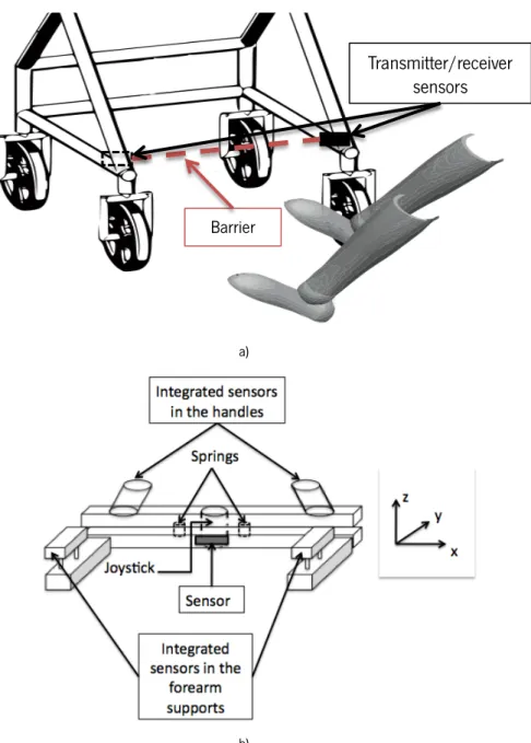
Figure 3.9 Schematic of the joysticks’ displacement. ... 51
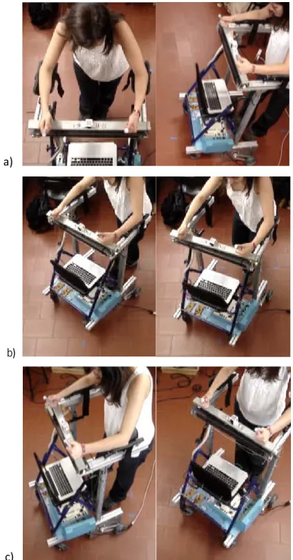
Figure 3.10 The user is a) walking forward, b) turning left and c) turning right. ... 52
Figure 3.11 Schematic of the sensors integrated in a) the lower base and b) the upper base of the walker. ... 54
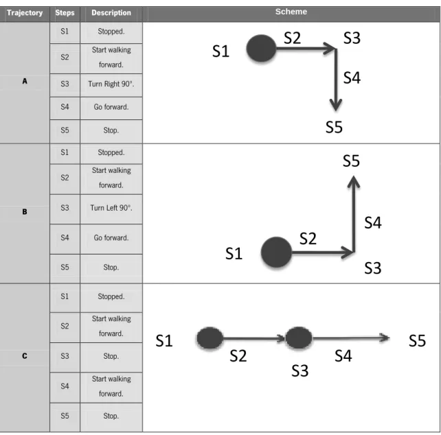
Figure 4.1 Typical raw Y (a) and Z (b) joystick data in the NeoASAS walker when the user is performing the three different trajectories explained in table 1: Top) A, Middle) B, Bottom) C trajectories. ... 62
Figure 4.2 Typical raw Y (a) and Z (b) joystick data in the ASBGo walker when the user is performing the three different trajectories explained in table 1: Top) A, Middle) B, Bottom) C trajectories. ... 63
Figure 4.3 Different phases of the trajectory B. S1- The user is stopped; S2- User starts walking forward; S3- User turns right; S4- User walks forward; S5 – User stops. ... 64
Figure 4.4 Typical raw Joystick data a) Y-signal and b) Z-signal obtained when the user is performing a translation curve (trajectory B) with the ASBGo walker. ... 65
Figure 4.5 Differente phases of the trajectory C. S1- The user is stopped; S2- User starts walking forward; S3- User stops; S4- User walks forward; S5 – User stops. ... 66
Figure 4.6 Diagram of the processing architecture of the Y and Z-signals. ... 67
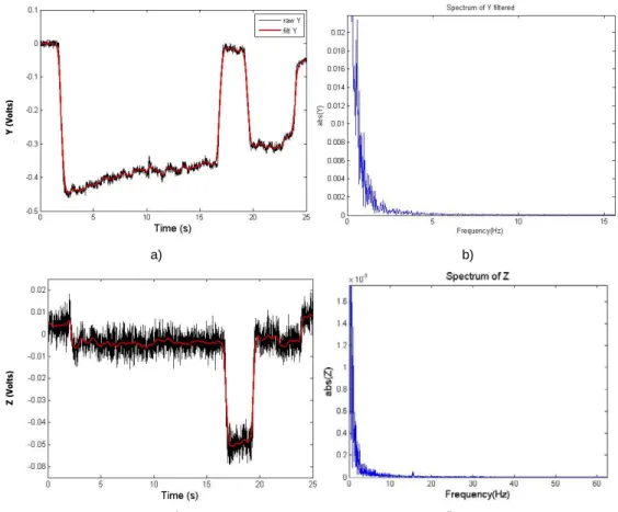
Figure 4.7 Example of a Frequency Spectrum for a) raw Y-signal and b) raw Z-signal. It is observed that user’s command intentions are below 2Hz and have considerable more energy than the noise components (higher frequencies). ... 68
Figure 4.8 Attenuation of higher frequency components by means of recursive digital filters (Butterworth) with 2Hz of cut-off frequency. a) The raw Y-signal (black) and the filtered Y-signal (red) with the digital filter; b) and d) Frequency Spectrum of Y and Z filtered, respectively,; c) The raw Z-signal (black) and the filtered Y-signal (red) with the digital filter. ... 70
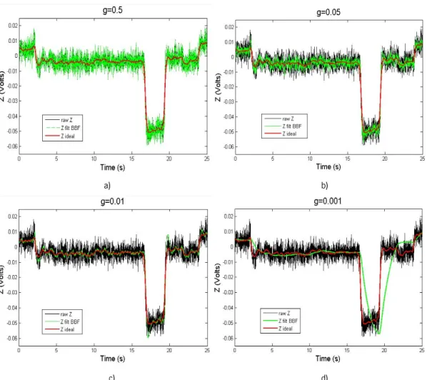
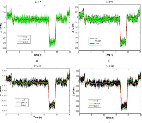
xvii Figure 4.9 Influence of the variation of the g parameter on the filter BBF. a) g=0.5, b) g=0.05, c) g=0.01, d) g=0.001. All graphs represent the raw Z signal in black, the filtered Z signal with BBF in green and the ideal Z in red. ... 75 Figure 4.10 Influence of the variation of the θ parameter on the filter CDF. a) θ=0.5, b) θ=0.95, c)
θ=0.99, d) θ=0.998. All graphs represent the raw Z signal in black, the filtered Z signal with CDF
in green and the ideal Z in red. ... 77 Figure 4.11 A complete Picture of the operation of the Kalman filter. ... 81 Figure 4.12 Measured state (raw Z) in black; estimated state (Z filt Kalman) in green and true state (ideal Z) in red. ... 83 Figure 4.13 Black: error between the true state and the measured state. Red: error between the true state and the estimated state. ... 84 Figure 4.14 a) The a priori error covariance (black) and the a posteriori error covariance (red); b) The kalman gain. ... 84 Figure 4.15 Measured state (raw Z) in black; estimated state (Z filt Kalman) in green and true state (ideal Z) in red. ... 85 Figure 4.16 Black: error between the true state and the measured state. Red: error between the true state and the estimated state. ... 86 Figure 4.17 a) The a priori error covariance (black) and the a posteriori error covariance (green); b) The kalman gain. ... 86 Figure 4.18 Measured state (raw Z) in black; estimated state (Z filt Kalman) in green and true state (ideal Z) in red. ... 87 Figure 4.19 Black: error between the true state and the measured state. Red: error between the true state and the estimated state. ... 88 Figure 4.20 a) The a priori error covariance (black) and the a posteriori error covariance (red); b) The kalman gain. ... 88 Figure 4.21 a) The superposition of the raw Z with the results of BBF, CDF and Butterworth; b) The superposition of the raw Z with the results of BBF, Kalman and Butterworth. ... 100 Figure 4.22 a) The superposition of the raw Z with the results of BBF, CDF and Butterworth; b) The superposition of the raw Y with the results of BBF, Kalman and Butterworth. ... 100 Figure 4.23 Attenuation of higher frequency components by the BBF filter a) The raw Z-signal, the ideal Z and the filtered Z-signal with the BBF filter; b) and d) Frequency Spectrum of Z and Y filtered
xviii
with BBF, respectively,; c) The raw Y-signal, the ideal Y and the filtered Z-signal with the BBF filter.
... 101
Figure 4.24 a) Z-signal filtered with BBF filter (g=16.87x10⁻³) and b) Y-signal filtered with BBF filter (g=44.29x10⁻³) . ... 101
Figure 4.25 Diagram of the circuit hardware for the processing of the Y-signal. ... 103
Figure 4.26 a) The raw Y-signal processed by software (black) and the Y-signal processed by hardware; b) The raw Y-signal without processing. ... 104
Figure 4.27 Comparison between the Spectrum of the raw Y signal (blue )and the Y-signal filtered by hardware (red) ... 105
Figure 4.28 Diagram of the circuit hardware for the processing of the Z-signal. ... 105
Figure 4.29 a) The raw Z-signal processed by software (black) and the Z-signal processed by hardware; b) The raw Z-signal without processing. ... 107
Figure 4.30 Comparison between the Spectrum of the raw Z-signal (blue )and the Y-signal filtered by hardware (red). ... 107
Figure 4.31 Attenuation of higher frequency components by means of recursive digital filters (Butterworth, first order). a) The Y-signal filtered by hardware (YH) in red and the YH filtered with the digital filter in black; b) Frequency Spectrum of Y and Z , respectively,; c) The Z-signal filtered by hardware (ZH) in red and the ZH filtered with the digital filter in black; ... 108
Figure 4.32 Complete system architecture implemented on NeoAsas walker. ... 110
Figure 4.33 Complete system architecture implemented on ASBGo walker. ... 110
Figure 5.1 a) Sketch of the walker with the markers and b) the lower limbs of the user with the markers. ... 114
Figure 5.2 Frames from the BTS shootings. The lower base of the walker and the lower limbs in 2D. ... 114
Figure 5.3 Sharp IR sensor (GP2Y0A21YK0F) ... 116
Figure 5.4 Sharp IR sensor integrated in the upper base of the ASBGo walker. ... 116
Figure 5.5 Typical IR output signal in trajectory a) A, b) B and c) C. ... 117
Figure 5.6 Typical IR output signal from user that is walking normally and then falls forward. ... 118
Figure 5.7 Algorithm to detect if the user is falling or not through the readings of the IR sensor output signals. ... 119
xix Figure 5.9 Mechanical device to support the sensor and ensure that the load made by the user on
the forearm support is enterly made on the sensing área of the Flexiforce sensor. ... 122
Figure 5.10 Assembly of the FlexiForce sensor with the forearm support. ... 123
Figure 5.11 Typical signal of the Flexiforce sensor when first, the user is not loading the sensor, and then loads. ... 123
Figure 5.12 Algorithm to detect if the user is falling or not through the readings of the flexiforce output signals. ... 124
Figure 6.1 Motors on walker’s structure of a) NeoASAS and b) ASBGo walkers. ... 130
Figure 6.2 Processing platform, Board control and batteries located on the lower zone of the NeoASAS walker. ... 131
Figure 6.3 Arduino Platform, H-bridges, sensors’ auxiliary circuits and the power source. ... 131
Figure 6.4 Membership function for a very negative value. ... 133
Figure 6.5 Fuzzy logic system diagram. ... 134
Figure 6.6 Examples of membership functions types [108]. ... 135
Figure 6.7 Inference and Generation steps of the Fuzzy logic system [108]. ... 137
Figure 6.8 Various defuzzification shemes for obtaining a numerical output [108]. ... 137
Figure 6.9 Membership functions for a) the forward input (Y), b) the rotation input (Z), and c) Motors. X-axis represents the numerical values of the inputs/outputs, and the Y-axis represents the degree of membership μ. These images are a print screen of the functions generated in Matlab. ... 140
Figure 6.10 Scheme of the behaviour of the fuzzy system while the user is performing trajectory A. ... 142
Figure 6.11 Scheme of the behaviour of the fuzzy system while the user is performing trajectory B. ... 143
Figure 6.12 System Architecture and control flow of the NeoASAS walker designed in Simulink. The control block is presented in detail. ... 145
Figure 6.13 Results from the system architecture of the NeoASAS walker acquired while the user was performing the trajectory A. a) raw acquired joystick signals and the result from the filtering with the BBF filter; b) signals before the amplification and restrictions; c) output of the fuzzy system (left) and the conversion and integration of these results to then be sent to the control board hardware (right). ... 147
xx
Figure 6.14 Results from the system architecture of the NeoASAS walker acquired while the user was performing the trajectory B. a) raw acquired joystick signals and the result from the filtering with the BBF filter; b) signals before the amplification and restrictions; c) output of the fuzzy system (left) and the conversion and integration of these results to then be sent to the control board hardware (right). ... 148 Figure 6.15 A schematic of the complete control architecture system used in the ASBGo walker. It starts with a circuit hardware block that sends signals to the Arduino platform. Then the outputs are sent to the H-bridges, which power the motors. ... 149 Figure 6.16 Results from the ASBGo system of the acquired while the user was performing trajectory A. a) acquired joystick signals after the pre-processing with the hardware circuit. b) signals before the amplification and restrictions in the Arduino platform; c) output of the fuzzy system (left) and then the conversion and integration of these results to then be sent to the H-bridges and then to the motors (right). ... 151 Figure 6.17 Results from the ASBGo system architecture acquired while the user was performing trajectory B. a) acquired joystick signals after the pre-processing with the hardware circuit . b) signals before the amplification and restrictions in the Arduino platform; c) output of the fuzzy system (left) and then the conversion and integration of these results to then be sent to the H-bridges and then to the motors (right). ... 152
xxi
List of Tables
Table 2.1 Assistive Mobility Devices ... 13 Table 4.1 Description of the three trajectories (A, B and C) performed by five individuals, five times each. ... 60 Table 4.2 SNR (signal-to-noise ratio) of the Y and Z signals (raw and filtered with the Butterworth filter). ... 69 Table 4.3 Uptade and Predictions equations of the g-h filter ... 73 Table 4.4 Average values* of the best solutions of the g parameter (BBF), delay between the Y original signal and the filtered signal and KTE for each Y joystick signal organized by subjects (1,2,3,4, 5) and trajectories (A, B, C). Table provides mean ± standard deviation. ... 91 Table 4.5 Average values* of the best solutions of the g parameter (BBF), delay between the Z original signal and the filtered signal and KTE for each Z joystick signal organized by subjects (1,2,3,4, 5) and trajectories (A, B, C). Table provides mean ± standard deviation. ... 92 Table 4.6 Average values* of the best solutions of the θ parameter (CDF), delay between the Y original signal and the filtered signal and KTE for each Y joystick signal organized by subjects (1,2,3,4, 5) and trajectories (A, B, C). Table provides mean ± standard deviation. ... 93 Table 4.7 Average values* of the best solutions of the θ parameter (CDF), delay between the Z
original signal and the filtered signal and KTE for each Z joystick signal organized by subjects (1,2,3,4, 5) and trajectories (A, B, C). Table provides mean ± standard deviation. ... 94 Table 4.8 Average Mean values* of the best solutions of the Q parameter (Kalman), delay between the Y original signal and the filtered signal and KTE for each Y joystick signal organized by subjects (1,2,3,4, 5) and trajectories (A, B, C). Table provides mean ± standard deviation. ... 95 Table 4.9 Average values* of the best solutions of the Q parameter (Kalman), delay between the Z original signal and the filtered signal and KTE for each Z joystick signal organized by subjects (1,2,3,4, 5) and trajectories (A, B, C). Table provides mean ± standard deviation. ... 96 Table 4.10 Best parameter solutions for each filter (BBF, CDF and Kalman). ... 97 Table 4.11 – Comparison between P initial value equal to the steady value, 0.5245, and P initial value equal to Q, using the average values of KTE and Delay, related to Y-signal, for each subject. ... 98
xxii
Table 4.12 Comparison between P initial value equal to the steady value, 0.5245, and P initial value equal to Q, using the average values of KTE and Delay, related to Y-signal, for each subject. ... 98 Table 4.13 Comparison between the proposed filters using the average values of the selected parameters for the 5 subjects for the Y signal. The presented average values correspond to the mean between the means of each trajectory .Table provides mean ± standard deviation. ... 99 Table 4.14 Comparison between the proposed filters using the average values of the selected parameters for the 5 subjects for the Z signal. The presented average values correspond to the mean between the means of each trajectory .Table provides mean ± standard deviation. ... 99 Table 4.15 SNR of the filtered Y and Z signals... 102 Table 6.1 General Membership Funtions. ... 135 Table 6.2 Membership funtions of the inputs/outputs of the fuzzy inference system. ... 139
1. Introduction
1.1. Motivation
The number of people with reduced mobility capacities increases every year. The reduction on mobility is a factor that influences both people quality of life and their dependence of others in daily life.
This demands the development of devices that can support and aid this people. Among the existing mobility assisting devices, walkers play an important role on giving lateral stability, balance, partial weight support, among others, to its large number of potential users.
1.2. Context
In this context, it is presented a project of a robotic walker that was first developed in the Consejo Superior de Investigaciones Cientificas (CSIC) with the Bioengineering Group, in Madrid, called NeoASAS project. Further, it continued in Minho University with the Adaptive System Behavior Group (ASBG) at Portugal, being designated by ASBGo project.
These projects propose the development of a command and control interface of a robotic walker. It is based on an earlier project called SIMBIOSIS, in which was demonstrated the great rehabilitation and functional compensation potential of an instrumented walker. The SIMBIOSIS also allowed the conclusion that a new instrumentation system was necessary if a commercial focus was to be faced.
The purposed walker will give continuity to the SIMBIOSIS project, developed in CSIC, maintaining its stability and reliability, but with a simplification on the instrumentation system, giving the aim on a commercial focus. Therefore, this system has to be implemented with simple and low cost sensors that can provide for an active safety device and generate strategies for a more natural and secure command interface to guide the walker. This walker is based on a conventional four-wheeled walker.
This thesis focuses on the characterization of assisted human-machine interaction during gait, using a joystick and other safety low cost sensors systems. It is aimed at the development of an
interaction strategy between the user and the walker to control two separate motors that will push the device, in a safe and user-friendly way. The integration of this interface pretends to decrease the cognitive effort required to the user when he is guiding the walker.
The work developed in CSIC was coordinated by Dr. Anselmo Frizera and Professor Ramón Ceres and was divided into four stages that were implemented over the five months of work.
The first stage consisted on reviewing the existing literature about the assistive devices for human mobility, conventional and Smart Walkers, among others and human-machine interfaces. On the second stage it was performed an introduction to the programming oriented to the NeoAsas using RT Matlab xPC Target. Then it was made the assembly of the electronic to acquire and extract the signals from the joystick. On the third stage, the walker was experimented using healthy volunteers. The experiments with the users were done without any motorization of the device. This was done to acquire the natural signals obtained through the interface without the interference of any control strategy. So, by studying the signals that are capture from the interface the real movement intentions of the user can be seen. Then, with this information it was characterized the interaction between both agents. It was found that the signal was composed by two components: one related to the vibrations caused by irregularities on the device’s wheels or the floor, and the other composed by transient events related to the guidance intentions. For each one of the components, a study to estimate them and/or eliminate them was necessary. Therefore, it was created a g-h filter to eliminate the vibrations from the signal.
After obtaining the data processing, a control strategy was implemented in the NeoASAS walker. This control strategy was based on fuzzy logic. The algorithm was developed to classify the signals sent by the joystick and transform them into motor inputs (direction and velocity). These algorithms were made in Simulink, MATLAB.
Finally, on the fourth stage it was made the validation of the control strategies of the guidance of the walker, adapting the programs to the electronic architecture. Necessary improvements were made during the validation. Then, new sensors and their localization were studied to improve the detection of dangerous situations.
This study was made with the help of a motion analysis system to analyse the position of the patient related to the walker, determining the possible places to integrate sensors that could detect possible falls of the user.
This study took continuity in Minho University, Industrial Electronics Department, under the supervision of Dr. Cristina Santos.
In the first stage of this work a new robotic walker was built, as well as its electronics. Through the mechanical modification of a conventional four-wheeled walker, the ASBGo was built. Thus, the first months were dedicated to the search of materials (steel, motors, pulleys, chains, sensors, forearm supports, handles, etc.) to the construction of the walker. A protocol was created with the company Orthos XXI that contributed with the conventional four-wheeled walker. Among the different types of walkers it was selected a four-wheeled to become possible the installation of sensors and motors for the driver of the walker. Among the four-wheeled walker it was given priority to one that allow the installation of the electronics and heavy components in the lower zone of the walker to improve the general stability of the set user-walker.
Then, it was searched for materials to modify the walker, as well as, DC motors, supports, handles, pulleys and others. When all material was found, the ASBGo was assembled. An additional structure was implemented to integrate the motors of the robotic walker and then an additional support base for the upper limbs, in order to find the best way to frame the interface that will be studied on the support.
The second stage consisted in surveying and extend the initial started state of art and write a journal review as well as an article about human-machine interfaces in Smart Walkers, including the work that is being developed in this thesis.
In the third stage, a study about the existing filter strategies suitable for this application, able to attenuate the noise components present in the joystick signals, was made, as well as experiments to find the best one to use here. The previously implemented g-h filter was more detailed studied as well as the Kalman filter. This stage involved both analytical, modelling and simulation phases.
The fourth stage consisted in designing the acquisition and processing architecture for the ASBGo walker. First, a hardware circuit to acquire, filter and amplify the joystick sensors was designed. Then, an Arduino platform was programmed with the control strategy studied in CSIC and adjustments were made. Finally, the connection to the motors through H-bridges was established.
The fifth stage began with experiments performed by 5 healthy volunteers. The joystick signals were acquired and analysed, as well as the signals sent to the motors. The validation of the designed hardware and the control strategy based in fuzzy logic was analysed and studied.
The sixth stage addressed additional safety issues. Firstly, research consisted in studying potential sensors to provide safety to the user during the use of the walker, to then select the more
suitable for this purpose. The decision about the sensors was based on price, precision measurement, type of power source and consumption, among others.
The idea was to find areas in the walker that could cover and identify dangerous situations, such as the backwards and forwards falls of a user. So these areas were studied and three were found: handles, forearm supports and upper base at the chest height.
In order to experiment and validate these areas, among some selected sensors, two types of sensors were selected: infrared sensors and Flexiforce sensors. These sensors were experimented, including experiments with users and its suitability was proven. The electronics and algorithm to classify the sensor signals were also developed and experimented.
At the end, a Smart Walker platform was built, with all the sensors interface integrated.
1.3. Objectives
In order to achieve the main aim of the proposed thesis, the following objectives have to be attained:
• Development and assembly of a Smart Walker platform based on a conventional four-wheeled walker and provide for the required modifications.
• Elaborate a critical review of the state of the art in the robotic technology for mobility assistive devices for people with mobility disabilities. The important role that robotics can play in mobility assistive devices is presented, as well as the identification and survey of mobility assistive devices subsystems with a particular focus on the walkers technology. It is presented a review of the available literature of walkers and it is discussed major advances that have been made and limitations to be overcome.
• The design of a robotic walker system. The sensory system must be integrated into an overall architecture to analyse the user interaction with the walker and to provide for his safety during the use of the walker.
• The development and implementation of control strategies, as well as the fusion of information of the sensors interface to detect the user’s intentions so that he can guide the walker.
walker.
• To delineate and implement the required experiments to validate the proposal.
This work aims to build a walker with an autonomous system capable of controlling the movement of the walker through the extraction of the users’ movement intentions obtained by the integrated sensory system. Thus, it seeks to develop a tool that provides for a clear benefit to a large number of people with limited ability to walk by improving the safety and reliability of walkers. Therefore, the users will avoid to inadequately resort to wheelchairs, that have disabling effects, thus contributing to the maintenance/improvement of the physical and cognitive capabilities of the user, through functional compensation.
1.4. Results from the thesis
A Smart Walker was built, implemented and validated, being a safe and stable device to support and help people with disabilities. In addition, a simple, user-friendly and intuitive interface was integrated into the device to allow an intuitive driven of the Smart Walker.
1.5. Structure of the thesis
This thesis is organized as follows.
In Chapter 2 it is presented a critical review of mobility assistance devices, with a special focus on the walkers as a tool for functional rehabilitation and compensation. This chapter has been proposed as an article review.
Chapter 3 does a brief presentation of the ASAS and SIMBIOSIS projects, followed by a presentation of the goals of the walker covered in this thesis.
In Chapter 4 it is described the main components of the signals obtained through the joystick and its potential to detect the intentions of the user to guide the walker. A processing strategy to improve/filter the signal is also presented.
In Chapter 5 it is described the additional safety measures included in this thesis and the characteristics of the applied infrared and FlexiForce sensors, as well as their potential to detect dangerous situations, such as, the fall of a user.
In Chapter 6 it is presented the control strategy implemented on the walker to attend the user movement intentions, as well as its validation on healthy subjects.
In Chapter 7 it is presented the conclusions and major contributions of this thesis, indicating possible areas of interest for future research on this area and to continue this work.
2. Review and Classification of Assistive
Mobility Devices
2.1. Introduction
During the twentieth century the proportion of older people had an important rise, and this trend is expected to continue into the twenty-first century. The proportion of population over 60 years old was 8% in 1950, and 10% in 2000, and it is estimated to reach 21% in 2050 [1]. Loosing complete or part of mobility, affects not only the ability to walk but also the ability to perform personal tasks, which is a major determinant in life quality and causes dependence of others in daily life.
In an aging society it is extremely important to develop devices, which can support and assist the elderly in their daily life, since their mobility degrades with age. This situation requires a great medical care, incurs large costs and can be fatal in some cases. Elderly tend to have cognitive impairments and experience more serious falls but there is strong evidence that daily exercise may result on fall prevention and postural stability [2]. So, it becomes more and more relevant to find ways and tools to compensate, to improve or to restore and to enhance this mobility.
For several years, researchers have been addressing the needs of persons with mobility disabilities alternative or augmentative devices [2]. These solutions are selected based on the degree of disability of the user. On the one hand, in case of total incapacity of mobility, alternative devices are used. These devices are usually wheelchairs or solutions based on autonomous especial vehicles [3-4]. On the other hand, the augmentative devices are developed to users with residual mobility capacities. They are used to avoid, whenever possible, the inadequate use of alternative devices, thus improving the physical and cognitive capabilities. These elements can be used as training mobility devices, self-ported devices, such as protheses or orthoses, or external, such as crutches, canes and walkers.
Among the external augmentative devices, the walkers assume an important role, due to the large number of potential users, considering its simplicity and ambulatory potential. They were designed to improve pathological gait, through a support base for the upper limbs that improves the balance of the individuals and reduces the load on their lower limbs [5]. In addition, use the person’s remaining locomotion capability in order to move [5], avoiding the early and deteriorative
use of wheelchairs. Over the past years, technological advances allowed the incorporation of sensors and actuators in conventional walkers, providing the stability of four-legged walkers, without affecting the resultant naturalness of the users’ gait patterns. Besides, these devices enable to identify the movement intentions of the users and therefore control the mobility assistance accordingly.
It is intended to cover all of the major developments in the mobility assistive devices described before, particularly focusing on the walker devices. In this chapter, it is presented a brief review of the causes and consequences of the gait dysfunctions that lead patients to use mobility assistive devices. Then, it is reviewed the literature regarding the corresponding mobility assistive devices. Finally, the literature regarding the walker’ devices is focused, presenting a more detailed review about the various existing models to date. It is presented a discussion of this information, summarizing the major accomplishments in the field and identifying the limitations to be overcome in future researches.
2.2. Gait Dysfunctions
The causes that affect the human mobility are rarely associated to only one disease [6].
The elderly are the ones that suffer more of mobility disorders, because the age causes a number of changes to mobility. Speed tends to decrease slightly and this is thought to increase efficiency of body motion since less energy is expended per stride. Less speed also allows better compensation of major muscle groups for any difficulties such as pain or weakness and allows less force to descend on any particular joint. There also tends to be some decrease in stride length. A decrease of speed and length may also play a role in maximizing balance and stability and be a natural way of helping prevent excess fall risk. [6]
The danger of falls in elderly people is due to high susceptibility to injuries caused by prevailing diseases e.g. osteoporosis or reduced protective reflexes. Besides the direct risk of fall-related injuries (e.g. major fractures or head trauma) another important consequence of falls is reduced mobility and loss of self-confidence, which in turn leads, therefore, to a significant reduction of quality of life. [7]
Disordered mobility, defined as a gait that is slowed, aesthetically abnormal, or both, is not necessarily an inevitable consequence of aging but rather a reflection of the increased prevalence and severity of age-associated diseases. These underlying diseases, neurologic and non-neurologic,
contribute to disordered mobility. Elderly patients usually have more than one condition contributing to their mobility disorder.
When asked about difficulties in walking, patients most often cite pain, stiffness, dizziness, numbness, weakness, and sensations of abnormal movement. Conditions seen in the primary care setting that can contribute to mobility disorders include degenerative joint disease, acquired musculoskeletal deformities, intermittent claudication, impairments following orthopedic surgery and stroke, and postural hypotension. Other conditions that cause mobility dysfunctions are hemiplegia, knee and hip diseases and metabolic disorders [6].
Walking is traditionally seen as an automatic motor task that requires little, if any, higher mental functions. In the past decade, new insights have drawn attention to the importance of cognition in daily walking. Normal walking requires strategic planning of the best route, as well as continuous interaction with the environment and with internal factors.
Failing to understand the significance of an obstacle, choosing an inappropriate route, or misinterpreting one’s own physical abilities can lead to falls. The safety and efficacy of normal walking rely not only on sensorimotor systems, but also critically depend on the interaction between the executive control dimension (integration and decision of action) with the cognitive dimension (eg. navigation, visual-spatial perception, or attention) and the affective dimension (mood, cautiousness, and risk-taking). A common situation where such integration is challenged is observed when people must walk while performing one or more secondary tasks. Lundin-Olsson and colleagues [8] were the first to note the significance of a failure to maintain a conversation while walking (“stop walking while talking”) as a marker for future falls. The ability to maintain normal walking while performing a secondary task has become the classic way to assess the interaction between cognition and gait.
In elderly people, this dual task ability deteriorates because central resources decline, secondary to subclinical disease processes or medication. This deterioration leads to a mismatch between the limited personal resources of elderly people and the complexity of the demand (the combined walking and secondary task). As a consequence, elderly people slow down or have increased stride variability (suggesting reduced automaticity) while performing a secondary task during walking. Gait becomes less secure and the risk of falling increases. In patients with overt disease, such as stroke or Parkinson’s disease, gait deteriorates even more during dual tasking [9].
It is noteworthy, that the elderly are not the only age group to suffer from mobility disorders. Any person that has cardiovascular problems, strokes, etc., can be affected with the mentioned consequences.
To reduce the degree of mobility disorder, the patient can be exposed to a medical intervention. This intervention is effective, but usually leaves some residual damage that cannot be reverse. Thus, it is important to consider other types of interventions like the use of mobility assistive devices for rehabilitation or functional compensation of the mobility, so that the patient can recover from his dysfunction without injuries.
2.3. Mobility Assistive Devices
Because of the many available devices and the importance of selecting the one best for each individual patient, a formal evaluation should be carried out by an experienced physical therapist before purchasing a device. Once the device is purchased, the therapist can make the appropriate equipment adjustments to meet the specifications of each patient and can provide training in the proper use of the device. Potential problems can be assessed by the physical therapist before the device is used [10]. In Table 2.1 is presented the different categories of assistive mobility devices and the corresponding purposes.
In case of total incapacity of mobility, considering both bipedestation and locomotion, the alternative devices, represented by the wheelchairs and the special vehicles, are the optimal solution. These have been the targets of intensive research, especially considering Autonomous Robotic Wheelchairs (ARW) [11-13].
Beyond the manual wheelchairs (Figure 2.1a) [14], offer robotic solutions able to provide for autonomous and assistive navigation to wheelchairs (Smart Wheelchairs) making use of human-machine interfaces, like BCI’s (Brain Computer Interfaces) and EMG (Electromyographic) signals [15-17] (Figure 2.1b). Additionally, some smart wheelchairs also enable a bipedestation position [19] (Figure 2.1 c)).
Table 2.1 Assistive Mobility Devices
Mobility Assistive Devices Examples Purpose Degree of
incapacity Alte rn ativ e Wheelchairs • Manual
• Autonomous with assistive navigation and/or bipedestation Transportation Total incapacity of mobility Autonomous especial vehicles • Autonomous vehicles to improve cognitive capacities; • Bipedestation Transportation. Improvement of cognitive capabilities. Au gm en ta tiv e Mobility-training devices • Parallel Bars • Treadmill-training devices • Ambulatory-training devices • Feet-manipulator training device
Mobility Rehabilitation Training
Residual mobility capacities
Self-ported devices • Orthoses
Functional Compensation (Supplement the function of the
limbs)
External devices
• Canes • Crutches • Walkers
Functional Compensation (Support during walking, to increase gait
stability, and balance) and Rehabilitation training.
a) b) c)
Figure 2.1 a) Manual Wheelchairs [14] and Smart Wheelchairs with b) BCI interface [18] and c) bipedestation position [19].
blood circulation and physiological functions, skin sores, among others. For these reasons considering the remaining locomotion capacities, it is interesting to encourage, whenever possible, the use of augmentative devices [5].
The augmentative devices can help the patient with reduced mobility to avoid the previously presented health problems and allow using the user’s patient remaining locomotion capability. In some cases, users can even relearn to walk safely and efficiently, in order to retrieve all the necessary movements for a normal gait. In other cases, these devices actuate like functional compensation elements that assist movements that the patient has lost. This means that the patient can learn new strategies to move, contributing to his independent locomotion on the daily life.
So, the augmentative devices can be used as 1) mobility-training devices during rehabilitation; 2) self-ported devices such as prostheses and orthoses, or 3) external devices, such as crutches, canes and walkers.
In the following, each of these types of augmentative devices will be described in more detail as well as the motivation for their use and evolution to more robotic systems when appropriate.
2.3.1. Mobility Training Devices
The mobility-training devices purpose is to help on the rehabilitation of the patient’s movements that have gait disabilities.
The most basic mobility-training devices are the parallel bars [20] (Figure 2.2). Their objective is to help people regain their strength, balance, range of motion, independence and to recover from some injuries, and other debilitating conditions. Patients are required to repeat concise movements that work more than one joint and muscle. Parallel bars are also used for ambulatory exercises to improve a patient’s ability to walk independently or with assistance. This kind of technique has shown to produce good results in terms of rehabilitation of patients [20].
Figure 2.2 Parallel Bars [20].
However, this therapy requires the involvement of two or three therapists to assist patients in walking, holding their lower limbs to control movement. Thus, it is required a substantial commitment and effort on the part of therapists [21]
Robotics appears applied to rehabilitation, resorting to the use of robots for mobility training of patients with disabilities.
It is known [22] that a new movement, or a qualitative improvement to an existing movement, can be achieved only through repetitions. Thus, therapy intensively addresses movement repetition in the training. This is the type of tasks that can be attempted by robotic devices. Research on this field led to the existence of robotic mobility training devices capable to expand the work of therapists so that each patient can receive enough therapy to easily attain an optimal recovery.
However, previous studies [23-25] have shown that patients have to be intensively engaged on the procedure; otherwise they lack interest with time, with a passive or no participation at all, causing bad results at the rehabilitation level. Their engagement must go beyond the novelty of the first sessions. Robotic mobility training devices are expected to provide to the therapists the necessary assistance to allow the patient to complete a certain task on locomotion; repeat as much as possible cyclic movements while motivating them to actively participate in the training.
Robotic mobility-training devices can be further divided into three different types of devices, according to the patients’ pathologies.
The first are the treadmill-training devices, which apply a treadmill while training. Some examples use a partial body-weight support, assisting patients to re-learn which reduces the weight supported by the patient while training; therefore patients can re-learn walking movements through repetition and task-oriented training. The main aim is to eliminate the need of the patients to deal with balance during the gait, focusing their concentration on the lower limbs movements. The treadmill-based training devices have been the most common method for mobility training.
The target patients of these devices are neurological target users (stroke, spinal injury, cerebral palsy) [22]. Their training mainly aims at improving the functional movements and sensorial stimulation through repetition. On the literature, there are well known devices like Lokomat [22], Lokohelp [26], LOPES [27] (Figure 2.3), whose goal is to provide an intensive training on movement repetition.
a) b) c)
Figure 2.3 Robotic mobility-training devices: a) Lokomat [22], b) LokoHelp [26] and c) LOPES [27].
The second type of devices, denominated by ambulatory-training devices, is quite similar to the previous ones, but do not use the treadmill. Comparatively to the former type of devices, these propose an over ground training that can be as effective as training over a treadmill, with the advantage that requires less equipment.
Their target users are patients, which suffer from musculoskeletal or neurological disorders (muscular dystrophy, amputee, multiple sclerosis, spinal cord injury, lower extremity joint pain). One of the most debilitating aspects for musculoskeletal or neurological disorders is the loss of the ability to ambulate [28].
Ambulatory devices explore the ability of the device to provide dynamic assistance in order to facilitate the movement of the patient, so that the patient can learn to walk with proper upright posture. On the literature, there are examples like the LiteGait [29], Walkaround [30], WalkTrainer [31], KineAssist [32], Where-II [33] (Figure 2.4) and Standimovi (Figure 2.5).
a) b) c)
Figure 2.4 Ambulatory-traning devices : a) LiteGait [34], b) KineAssist [32], c) Where-II [33]
Standimovi is currently in development at the Bioengineering Group – CSIC and the author of this thesis has actively participated in the first stages of the development and validation of its electronic platform.
This device is a self-guided ambulatory training device based on the integration of a human-machine interface to drive and adapt the device to the user’s requirements. Thus, this system aims to provide a higher degree of technical aid, to help patients to get autonomy to improve their remaining mobility capacity and mental state. Additionally, Standimovi also allows the patient to be transferred from the wheelchair to a walking position, without the help of others, with a safely and easily mechanism. The device and its mechanism are shown in figure 2.5.
Finally, the third type of devices denominated by feet-manipulator training devices, are based on holding the patient’s feet to a robotic manipulator. It supports and gently leads the patients in the continuous practice of walking situations. The wheelchair-bound patient is attached to a steel frame in a type of harness, their feet on plates whose trajectories can be fully programmed and imitate everyday walking situations: walking on a level, tripping, slipping or climbing up and down stairs. Reacquiring these abilities is essential for mobility in everyday life. The objective is to copy these movements as naturally as possible. As a result of these artificial feet movements the slack muscles between the toes and the hips are forced into action again.
These devices address patients who have neurological disorders. In the literature it can be found examples like the GaitTrainer [35] and the HapticWalker [35] (Figure 2.6).
Figure 2.6 a) GaitTrainer [35], b) HapticWalker [35].
The described devices manipulate the legs, according to the kinematics provided by each mechanism and the speed desired. However, they need to be permanently installed in a room. They require that patients have to be moved from their beds to that room to experience the robotic rehabilitation. Unfortunately, depending on the healthy state of the patients, it may not always be possible to move the patient out of his bed to start the rehabilitation therapy. Additionally, waiting may imply destruction of cortical tissues, and less possibilities of recovering these neural functionalities [36].
To overcome the above-mentioned limitations, it was designed the NEUROBike [36] presented in figure 2.7. The NEUROBike system is a robotic device dedicated to the recovery of walking skills in stroke patients during the acute phase, when they are on bed, not yet able to keep a safe upright posture and walking. The system has been designed in order to provide, as soon as possible,
rehabilitation therapy, thus avoiding as much as possible further damages of the cortical tissues due to their non-use [37], and to facilitate neural function recovery with repetitive exercise.
Figure 2.7 NEUROBike [36]
2.3.2. Self-ported Devices
Self-ported devices are carried by the user either to improve function of movable parts of the body (orthoses) or to substitute a lost member (prostheses) [38]. Between these two, orthoses are the ones that present an intense physical and cognitive interaction with the user, and are intended to offset the loss of mechanical function and work together with the movements of the patient. Orthoses allow the patient to perform a wide range of locomotor tasks on the ground, compared with the other mobility-training devices. Their function is to mechanically compensate or enhance functionally of the damaged member, acting in parallel with it [39].
Orthoses can be active or passive. Active orthoses bring the necessary energy to enable the movement by applying actuators or motors. These types of orthoses use actuators or motors. For a detailed survey verify work of AM Dollar [38] and N Costa [51]. HAL-5 (Hybrid Assistive Limb) [40], ReWalkTM [41], RoboKnee [42], MIT active AFO (ankle-foot orthoses) [43], MIT active ankle-foot
orthoses [44] (Figure 2.8), and GAIT [45] are some examples that can be found in the literature. Passive orthoses (Figure 2.9) don’t provide energy, and remain passive. Energy is provided by the user. These devices only use springs and links and are based on the Gravity-Balancing principle [46]. This principle takes advantage from the gravity force to balance the gait of the patient.
a) b) c) d)
Figure 2.8 Self-ported devices: Orthoses a)HAL-5 exoskeleton [40], b) ReWalkTM [41], c) RoboKnee [42], d) MIT active ankle-foot orthoses[44].
Figure 2.9 Passive Orthoses based in the Gravity-Balancing Principle [46].
2.3.3. External Devices
Canes, crutches and walkers represent the external devices. These devices are indicated to help users with balance problems and for partial weight-support.
Canes are more commonly used to increase the gait stability than to partial weight-support. A simple single point cane may prevent or reduce falls in patients with imbalance. An example is the standard cane [47] (Figure 2.10a). However, it does not seem to help falls due to retropulsion, which contributes to falls. So, there are canes that can provide greater support, like the multi-feet cane [47] (Figure 2.10b).
Crutches (Figure 2.10c) are orthopaedic devices that allow a direct support of the body thus providing great stability and balance in walking and a greater weight support compared with the canes. However, the crutches are cumbersome and are increasingly out of favour because they provide an unnatural gait.
As robotic examples of canes, it can be found the SmartCane [48] and the GuideCane [49]. (Figure 2.10d and figure 2.10e)
a) b) c) d) e)
Figure 2.10 External Devices: a) Standard Canes [59], b) Multi-feet cane [10], c) Crutches [50], d) SmartCane [48] and e) GuideCane [49]
Finally, walkers are the devices from this group that provide greater support. They can have feet or wheels and are pushed by the user using hands or the forearms to guide the device. As this work is devoted to the study of these specific devices, it will be presented, on the following section, a detailed critical review about the walkers.
2.4. Walkers
Walkers assume an important role due to its simplicity and rehabilitation potential. These devices are interesting once they work as a supporting device during bipedestation and, in addition, use the person’s own remaining locomotion capability in order to move [5] avoiding the early and deteriorative use of wheelchairs.
Walkers are prescribed to improve patients’ mobility and help them maintain balance [10] [52]. The devices can increase confidence and sense of safety, which can raise a patient’s level of activity and independence. There may be physiological benefits of limiting osteoporosis, reducing cardiopulmonary deconditioning and improving peripheral circulation [10].
Static equilibrium is maintained when the body’s centre of mass is positioned over the base of support. Loss of balance can result when the centre of mass is displaced in relation to the base of support because of voluntary movements or external perturbations, such as slips, trips or pushes. Use of a walker increases the base of support, thereby allowing a greater tolerated range for centre
of mass [66]. They can also prevent instability by allowing stabilizing reaction forces such as holding on or pushing against the ground [10].
There are many types of walkers, considering their constitutive materials, accessories, sizes and structural configurations. These are classified them in two types: Conventional and Smart Walkers, detailed described on the following.
2.4.1. Conventional Walkers
An important aspect that classifies conventional walkers is the ground contact configuration, so they are classified by its type of support with the ground [5]: Standard, Front-wheeled and Rollators.
a) b) c)
Figure 2.11 Conventional Walkers: a) Standard walker [55], b) Front-wheeled walker [55] and c) Rollator [10].
The Standard walker (Figure 2.11a) is a metal, four-legged frame with rubber tips, which must be lifted and moved forward while walking. This type of walker is used when maximum assistance with balance is required or when restrictions on weight bearing are present. While easier to use than a cane, this type of walker does require some degree of upper body strength and cognitive ability to use safely, and results in a fairly abnormal gait [61]. This device has also little value for retropulsion (many patients fall over backwards still holding their walker) and propulsion [10].
The Front-wheeled walker (Figure 2.11b) is designed for people who have weaker upper-limbs or that tend to fall backwards when lifting the device. This type of walker promotes a forward displacement of the center of gravity and allows a more normal gait, as the person can continue walking without stopping to lift the walker. It is particularly useful in patients with Parkinson’s disease, as it reduces the risk of falling backwards. Cubo et al. [54] studied Parkinson patients who had gait freezing with objective measures and found that although standard walkers may stabilize
patients and may increase confidence, walking speed actually slowed when using a walker. In this study, the standard walker increased freezing and the wheeled walker had no effect on freezing.
In addition, it is less likely to allow the patient to pick up speed as he goes along, relatively to the four-wheeled walker [5].
The studies [10] show that most patients now prefer the Rollators (four-wheeled) compared to the other conventional walkers (Figure 2.11c). They do not need to be picked up, but have modern wheel systems so they roll and pivot smoothly and with little effort. They promote the most natural gait patterns. They are the easiest to use of the three types, but also provide the least stability. Wheeled walkers for use in the community can be equipped with baskets for shopping, and a seat that allows the person to stop and rest, if required [5]. Hand brakes can be selected to stop the device when squeezed or when released [10]. However, the user must be capable of learning to apply the brakes in order to use them safely [5]. Another option is the presence of a padded bar across the front that initiates braking if the patient presses or falls onto it. This bar is useful for patients with poor grip strength, speed or dexterity [10].
For example, Boomer [53], presented in figure 2.12, was designed by Daniel Molloy, Australia, and has a futuristic aesthetic. It allows the user to climb stairs: by pushing a bottom the front wheels can move along to near the back wheels so that it becomes a kind of cane that helps in the up and down of the stairs. The user can support his weight on the structure safely, because the wheels are locked and have a linear motion from top to bottom in order to help to climb the stairs.
Figure 2.12 Climbing the stairs with Boomer [53].
Another example is the U-Step walking stabilizer [56], of the In-Step Mobility (Figure 2.13). Its velocity can be adjusted through crank, as well as the height. Its structure can have also a compact form (Figure 2.14).