Revest i ment o não-ader i do: cr i t ér i os desempenho
est r ut ur al e dr enabi l i dade
Luiz Fernando Batista da Silva
Ercio Thomaz
Luciana Alves de Oliveira
Abstract
ladding systems have significant effect on the performance and durability of building façades, contributing to the building
watertightness, property valuation, aesthetic finishing, and decoration. Non-adherent cladding, also named rainscreen cladding or ventilated cladding, is currently used in residential and commercial buildings, new
constructions, or retrofit operations, and it is considered an efficient measure to improve the moisture safety of building envelopes. Therefore, the absence of Brazilian normalization to ventilated cladding systems is one of the difficulties limiting its increased local application. In Brazil, a technical standard, NBR 15575, parts 1–6, (2013), establish the general performance requirements and test methods to evaluate residential building systems including structure, wall, floor, coverage, and hydraulic installation. However, this standard cannot be integrally applied to the cladding systems because it was developed considering the vertical wall system as a whole. In this study, we propose the criteria and test methods for assessing ventilated cladding systems while taking into account the structural safety (wind loads resistance, hard and soft impact resistance) and drainability requirements. The following activities are performed: literature review, practical case study, and tests on prototypes for validation of the proposal. The tests allow verification of the feasibility of the criteria and tests methods proposed. In addition, the proposal makes it possible to guide design, construction, and maintenance needs, thereby inducing the growth of this technology in Brazil.
Keywords: Ventilated cladding systems. Rainscreen claddings. Building Performance
criteria. Moisture safety. Test methods.
Resumo
O sistema de revestimento não-aderido (RNA) influencia o desempenho da fachada dos edifícios, pois impacta na durabilidade, estanqueidade à agua, estética e valorização do imóvel. O RNA, também denominado pelo mercado como fachada ventilada, é frequentemente utilizado em fachadas de edifícios residenciais, comerciais, novas construções, renovações ou retrofit, considerado também uma forma eficiente de reduzir os problemas de umidade da fachada. Entretanto, a ausência de normalização técnica específica limita o crescimento do uso desta tecnologia no Brasil. Além disso, no Brasil, existe a NBR 15575, partes 1-6 (2013), que estabelece critérios de desempenho, bem como os respectivos métodos de avaliação para avaliar os principais sistemas do edifício: estrutura, piso, vedações verticais, cobertura e instalações. Entretanto, esta norma pode somente ser parcialmente adotada para o RNA, pois a NBR apresenta critérios considerando toda a fachada e, não somente, o revestimento. No presente artigo são propostos critérios de desempenho e métodos de ensaio aplicados para RNA, particularmente abordando os requisitos de segurança estrutural (resistência a cargas de vento, e a impactos de corpo mole e corpo duro) e drenabilidade. Para este estudo, as seguintes atividades foram realizadas: revisão bibliográfica, estudo de caso e ensaios em protótipo para validar a proposta de critérios e métodos de ensaios.
Palavras-chave: Fachada ventilada. Revestimento Não-Aderido. Critérios de
C
Luiz Fernando Batista da Silva Inst it ut o de Pesquisas Tecnológicas do Est ado de São Paulo São Paulo - SP – Brasil
Ercio Thomaz Inst it ut o de Pesquisas Tecnológicas do Est ado de São Paulo São Paulo - SP – Brasil
Luciana Alves de Oliveira Inst it ut o de Pesquisas Tecnológicas do Est ado de São Paulo São Paulo - SP – Brasil
Introduction
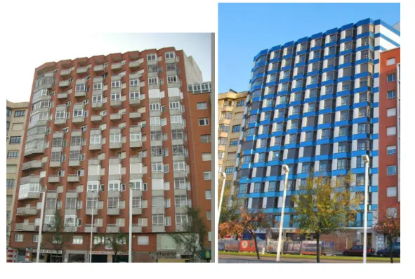
Façade systems are comprised of several layers such as a wall and cladding, of which the latter is the most exterior layer and it may or may not be bonded directly (adhered) to the substrate (wall). According to some previously reported publications by Resende, Barros e Medeiros (2001), Ribeiro and Barros (2010), and Becere (2007), a cladding system has a significant influence on the performance and durability of a façade as it contributes to the building watertightness, valorization, aesthetic finishing, and decoration. One of the cladding technologies currently being used in residential and commercial buildings, new construction, or retrofitting (Figure 1), is the non-adherent cladding system, also named as rainscreen cladding or ventilated cladding. In such a system, there is an air space between the cladding elements and external wall, and the air space is always drained and may be kept ventilated. Usually, the elements used as the external cladding include extruded ceramic tiles, porcelain tiles, fiber cement boards, aluminum composite panels, and phenolic boards.
Employing rainscreen and ventilated cladding is a common measure to improve the moisture safety of building envelopes, and in addition it serves as a capillary break and a drainage plane between the exterior climate and the inner group of structural elements and substrate (STRAUBE; FINCH, 2009; LANGMANS; ROELS, 2015).
Presently, in Brazil, several companies are providing ventilated cladding systems and their use is increasing (ARCO, 2012). However, there are no technical standards or regulatory documents that specify and set guidelines to design, build, and maintain cladding systems, and neither there is a performance assessment concerning their safety, habitability, durability, serviceability, and maintainability.
Therefore, the lack of Brazilian normalization in reference to ventilated cladding systems is one of the difficulties in homogenizing their design, construction, and use while taking into account aspects related to safety, habitability, durability, and maintainability. Consequently, this impacts the decision-making phase in which the façade technology is selected.
In Brazil, NBR 15575 (ABNT, 2013), a general performance standard applied to residential buildings, sets the requirements and evaluation methods for the five most important building elements, namely, structure, wall, floor, coverage, and hydraulic installation. However, this standard
cannot be adopted for the cladding system as it applies to the entire wall system. Among the national standards, NBR 10821 (ABNT, 2011a) provides some of the requirements and evaluation methods for structural performance (wind loads) and durability that can be adopted for the ventilated cladding systems.
Among the foreign documents and standards, some items of the American Society for Testing and Materials (ASTM) can be used as a reference to perform the technical assessment of the cladding systems, for instance, these systems must provide airtightness (AMERICAN…, 2012), evenly distributed loads (AMERICAN…, 2014), and resistance to water pressure (AMERICAN…, 2009).
The European Organization for Technical Assessment (EOTA) published, in June 2012, the European Technical Approval Guideline (ETAG 034) (EUROPEAN…, 2012a) that is a regulatory document establishing the performance requirements and evaluation methods for cladding systems by considering their mechanical strength and stability, fire safety, safety in use, protection against noise, energy savings, thermal characteristic, and durability.
regulations such as ASTM and ETAG do exist, it is not possible to adopt them in the Brazilian context without appropriate adaptation.
Ventilated cladding systems with open joints do not have to be watertight. However, they must provide protection such that they reduce the water incidence into the substrate (wall), which is the rainscreen phenomenon (ROUSSEAU; POIRIER; BROWN, 1998). This performance for reducing the water incidence into the substrate is known as the drainability requirement; it is the capacity of the cladding to drain out the water that penetrates into the air space or the condensed water, with the aim of reducing the moisture damage on the building façade.
Moisture accumulation in the air space between the cladding and substrate can facilitate migration of water into the building over time, which can in turn generate condensed water for the useful life of the system and cause staining and dirt on the external surface of the cladding (TRECHSEL; BOMBERG, 2009). Contribution of the ventilated cladding to the façade watertightness exhibited in the drainability assessment suggests conduction of a study to optimize the waterproof products applied to the substrate.
The requirements hereby discussed can be adopted by several configurations of ventilated claddings independently of the cladding elements or fixation devices. Therefore, we will not discuss the individual characteristics of each component that forms the cladding system.
This paper is divided into the following six parts: (a) purpose and introduction;
(b) brief description of the ventilated cladding system;
(c) research method;
(d) proposed Performance Criteria;
(e) methods and test result (proposal validation); and
(f) conclusions.
In this paper, we have adopted the following terminology (from ETAG034 (EUROPEAN…, 2012a)):
(a) air space: space between the cladding and substrate.
(b) cladding kit or cladding system: is a specific kit made of an external cladding and defined fixing devices.
(c) substrate: refers to a wall that meets the necessary airtightness and mechanical strength requirements (resistance to static and dynamic loads).
(d) subframe: an intermediate assembly of vertical and/or horizontal metal profiles, located between the cladding elements and the substrate.
(e) cladding element: sheet, tile, board, panel or cassette made of durable material applied at the external face of a wall such as: fiber cement, stone, ceramics, metal, plastics, brick slips, etc.
Brief description of the
ventilated cladding system
Marble and granite associated with mechanical fixings were used in the Kaiser Franz Josef Project at the onset of the 20th century, which is one of the first records of a ventilated cladding application. A similar cladding was used during the construction of the São Leopoldo church in Steinhoff, Austria, between 1905 and 1909; marble claddings 20-mm thick was mechanically fixed to the substrate via copper anchors (PATÓN, 1995).In the recent past, the Institute for Research and Coordination in Acoustics/Music (IRCAM), stands out as one of the first buildings in the 1970s to apply a ventilated cladding on its façade. Renzo Piano and Richard Rogers have designed the façade using ceramic claddings (PIANO, 2016).
Presently, there are several materials such as porcelain tiles, ceramics, fiber cement panels, stones, metal, resin mortar, and others chosen as cladding elements so that numerous architectural solutions are possible during the façade design. Ventilated cladding is wrongly associated with ventilated façade, curtain walls, double skin façade, and other technologies with similar aspects (SIQUEIRA JÚNIOR, 2003). The ventilated cladding kit is the most external layer of the wall and it only has the cladding function contributing to the façade watertightness, valorization, aesthetic finishing, and decoration.
Therefore, the ventilated cladding kit is a specific kit made of an external cladding, defined for fixed devices that are normally, but not always, delivered together on site. The cladding is mechanically fixed to the wall (substrate) using a subframe. The space between the cladding element and wall is intended to be a ventilated air space (EUROPEAN…, 2012a; VEDOVELLO, 2012).
According to ETAG 034 (EUROPEAN…, 2012a), external wall claddings are considered ventilated when the distance between the cladding elements and substrate (ventilation air space) is at least 20 mm. In addition, the ventilation openings are envisaged, as a minimum, at the building base point and at the roof edge with cross-sections of at least 50 cm2 per linear meter.
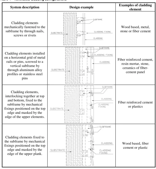
Cladding kits have different configurations based on their fixing devices and cladding elements as shown in Table 1 and Figure 2.
The layout of the subframes varies according to the design, cladding elements, dimensions, substrate, and construction details.
Among the ventilated cladding kit alternatives, Machado (2012) and Siqueira Junior (2003) explain that aluminum subframes anchored to the substrate are commonly used in Brazil.
Anchoring devices are responsible for fixing the subframe to the substrate and transferring the cladding loads to the building structure. The anchors can be classified into two groups. The first group includes cast-in-place anchors that are installed during concreting or other substrate execution. The second group is the post installation anchors that are fastened to the finished substrate. Fixing devices are designed considering the material of the cladding elements. The fixings can be clips, screws, and nails, which respect the design solutions. The criteria and test methods we have proposed have the potential to assess the performance of all the cladding solutions (configurations illustrated in Table 1).
Research methods
The current work has been developed based on the the following activities:
(a) bibliographical review: information relating to ventilated cladding systems reviewed, for instance, manuscripts, theses, and national and international technical standards. The main bibliography is ETAG 034, the basis of the proposals set in this work;
(b) case study: design analyses and visits to a building with ventilated cladding kits were conducted. This study was performed in the city of São Paulo, Brazil. Analysis of the design and construction aspects of this case study allowed the development of an understanding of the on-site application of the system. The feasibility of meeting the performance criteria and ability to perform the respective tests methods was verified by conducting the tests on the prototypes
(described later on item “c”) that were designed and executed taking into account the cladding kit of the case study; and
(c) tests on the prototypes for verification of the feasibility of the proposals: tests were performed to verify the structural and drainability
performance of the cladding system considered. For assembling the specimen, we adopted a cladding system similar to the building in the case study. The specimens were constructed to simulate the use conditions, including the air space and open joints.
Proposed performance criteria
Structural performance
The ventilated cladding system is not responsible for the stability and structural performance of the building. However, it is required to support its non-load bearing parts and transmit wind non-loads to the main structure without one of its parts falling and endangering the users.
Table 1 – Ventilated Claddingconfigurations
System description Design example Examples of cladding
element
Cladding elements mechanically fastened to the
subframe by through nails, screws or rivets
Wood based, metal, stone or fiber cement
Cladding elements installed on a horizontal grid of metal rails or pins, screwed to a
vertical subframe by through aluminum alloy profiles or stainless steel
pins
Fiber reinforced cement, resin mortar, stone,
ceramics of fiber-cement panel
Cladding elements, interlocking together at top
and bottom, fixed to the subframe by mechanical fixings positioned on the top
edge and masked by the edge of the upper elements.
Fiber reinforced cement or plastics
Cladding elements fixed to the subframe by mechanical fixings positioned on the top edge and masked by the edge of the upper plank.
Wood based, fiber cement or plastic
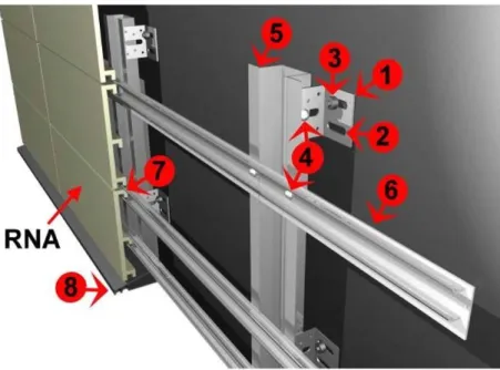
Figure 2 – External claddings parts
Note:
1 Anchorage;
2 Obl ong hol es t o f it t he screw; 3 Screw;
4 Met all ic grid; 5 Met all ic Subf rame;
6 Rail – part of t he cl adding f ixing; 7 Cl adding f ixing; and
8 Wat er drainage device.
Furthermore, the cladding kits must be stable to the combined stresses generated by the normal loads such as regular weight, temperature, humidity, and shrinkage, as well as movements of the substrate, direct impacts (soft and hard impacts), and wind forces (pressure and suction). Therefore, the following aspects must be considered to calculate and evaluate the structural performance:
(a) normal load resistance: the system should support its own weight without excessive deformation and shattering;
(b) impact load resistance: the system must be designed to maintain its stability when submitted to impacts caused by regular use. Accidents, maintenance activity, or vandalism actions caused by widespread impacts should not cause damage resulting in injuries to the users, such as those inflicted by sharp edges or the falling of components on the users. In addition, impact damage should not crash the system, thereby compromising the satisfaction of the performance requirements. In case of a rupture, the cladding elements cannot present sharp edges and their surface should not cause bodily harm to users or bystanders;
(c) wind resistance: the cladding system must exhibit an appropriate mechanical resistance to the
forces of pressure, suction, and vibration owing to the wind; and
(d) hygrothermal variations resistance: the cladding system must withstand movements caused by humidity and temperature changes, except at the structural joint where special precautions have to be taken in the design.
Once the main loads that the cladding kits will be subjected to (items "a" to "d") are calculated, the subframe must be assigned dimensions according to the relevant technical standards. In the Brazilian context, the standards are NBR 8800 (ABNT, 2008), NBR 6123 (ABNT, 1988), and NBR 14762 (ABNT, 2010).
The fixing devices (screw, anchors, and nails) must be evaluated according to NBR 14827 (ABNT, 2002a) and NBR 14918 (ABNT, 2002b), whereas ETAGs 001 (EUROPEAN…, 2012b), 020
(EUROPEAN…, 2012c), and 029
(EUROPEAN…, 2013) are used to support the structural calculation of the subframe.
Wind load resistance
Kumar, Stathopoulos and Wisse (2003) demonstrated the insufficiency of national and international wind codes and standards for developing ventilated cladding (rainscreen walls) designs, and thereby, highlighted the need for performing tests to study the diverse situations. In addition, the authors also estimated the impact of various design parameters on the wind loading on the rainscreen; however, they did not explain how to formulate a wind test that considers all the different situations. Currently, ETAG 034 (EUROPEAN…, 2012a) is adopted as a reference for the wind load resistance evaluation of a ventilated cladding.
According to ETAG 034 (EUROPEAN…, 2012a), […] both the tolerance due to manufacturing and/or installation and deformations due to temperature and humidity variations have to be taken into account and the most critical case shall be tested […].
Furthermore, it highlights that the test results are only valid for those fixing patterns that are tested. Therefore, ETAG 034 proposes that the results of the mechanical test to evaluate the wind resistance must generate the follow information:
(a) the load “Q” for which the test specimen fails (rupture load);
(b) the type of failure; and
(c) the value of deflection as a function of the load, given in a graphical form.
Failure is defined by one of the following events: (a) cladding element breakage; and
(b) significant permanent deflection of a cladding element: failure of fixings: failure or detachment of the frame.
The tests proposed by ETAG necessitate reaching the rupture of the components without setting the deflection limit. In Brazil (because of the equipment limitation), it will not be possible to reach the
rupture load in all situations. Therefore, this study proposes to conduct the wind load test in Brazil by considering the criteria in NBR 10821-2 (ABNT, 2011a) (standard for glass curtain wall), however, with a few adaptations as it is a standard applied to façade components. The loads (pressure or suction) are set considering the service and rupture loads. Thus, the cladding kit should not exhibit the following performance when submitted to service loads caused by the wind:
(a) total rupture or partial collapse of any of the components including the cladding element; (b) maximum instant deflection of L/175, where “L” is the free length of the profile under consideration and is limited to 30 mm;
(c) residual deflection less than 0.4% of the free length of the profile, measured after 3 min of the shutdown of the test pressure; and
(d) failure of fixings.
For the rupture loads, the cladding kit cannot exhibit rupture, total or partial collapse of any of the components, including the cladding elements. In general, the rupture load is 1.4 or 1.5 times higher than the service load.
Impact resistance
According to ETAG 034 (EUROPEAN…, 2012a), for setting the impact energy, the categories listed in Table 2 should be considered corresponding to the degree of use exposure. This table does not include any allowance for acts of vandalism. Table 3 presents the performance criteria relating to the hard and soft impact resistances set by ETAG 034, considering the use categories.
According to ETAG 034 (EUROPEAN…, 2012a), […] the approval body shall establish that the cladding product does not present sharp or cutting edges and its surfaces do not cause bodily injury, to the occupants or people nearby […].
Table 2 – Definition of use categories (EUROPEAN…, 2012)
Use Category Description
I A zone readily accessible at ground level to the public and vulnerable to hard body impacts, but not subjected to abnormally rough use
II
A zone liable to impacts from thrown or kicked objects, but in public locations where the height of the kit will limit the size of the impact; or at lower levels where access to the building is primarily to those with some incentive to exercise care.
Table 3 – Impact categories (EUROPEAN…, 2012a)
Category IV Category III Category II Category I
Impact 1 J cladding element not cracked (2) - - -
Impact 3 J - cladding element not cracked (2) No deterioration(1) No deterioration (1)
Impact 10 J - - Cladding element not cracked (2) No deterioration (1)
Impact 60 J - - No deterioration(1) No deterioration (1)
Impact 300 J - - No deterioration(1) -
Impact 400 J - - - No deterioration(1)
Note: (1)Superf icial damage, provided t here is no cracking, is considered as showing “ no det eriorat ion” ; and (2)The t est resul t is assessed as being "cracked" if circul ar cracks penet rat ing are observed.
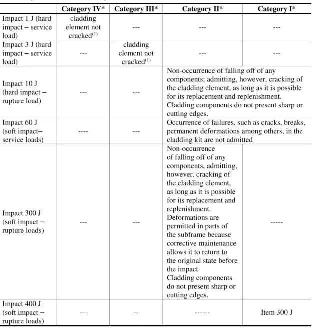
Therefore, in the Brazilian context, we propose to include other points with these performance criteria (set on Table 4), which detail the rules and take into account the service and rupture loads, such as the wind resistance assessment, avoiding subjective analyses.
The cladding designer together with other stakeholders of the building production is responsible for deciding whether the cladding must also exhibit the impact performance in the upper floors (effects of hail storms, etc.). However, it is proposed that in regions predisposed to be submitted to impacts by objects thrown or kicked, such as in areas of public access, or on floors of public access, the test of impact of 300 J should be performed.
Drainability
The cladding kit must contribute to the watertighness of the external walls, reducing the penetration of rain inside the building. According to ETAG 034 (EUROPEAN…, 2012a), the drainability of a cladding kit is generally assessed based on the design, taking into account the characteristics of the materials, geometry of external cladding, thickness of the air space, and joints among cladding elements. In addition, the drainability of water in the kit should be visually assessed.
Therefore, the drainability assessment aims to analyze the relationships of the volume of rainwater hitting the façade with the wind pressure and volume of water that penetrates into the air space and hits the wall (substrate). This enables verification of the eventual concentration of water in the profiles of the subframe cladding.
This assessment can be made via design analysis, verifying the air space thickness (EUROPEAN…, 2014). However, in non-regular façades with various geometric configurations or with different shapes than those contemplated by NBR 6123
(ABNT, 1988), a more detailed analysis is required to determine the amount of water that passes through the cladding and reaches the substrate (wall).
Thus, for drainability assessment, we propose calculating the relation between water sprinkled and water captured during the test, i.e., water that reaches the substrate and water collected (during and after the test). Such information will make it possible to analyze if waterproofing the substrate and the air space thickness specified in the design are suitable for promoting watertightness of the external wall (substrate + ventilated cladding). By means of the tests, it was possible to estimate that 5% is an appropriate relation between water sprinkled and water captured to promote the tightness of the façade.
Methods and results of tests
This section describes the proposed test methods and the tests that were performed to demonstrate their feasibility and to show that the results can attain the proposed performance criteria.Structural PERFORMANCE
Wind load resistance
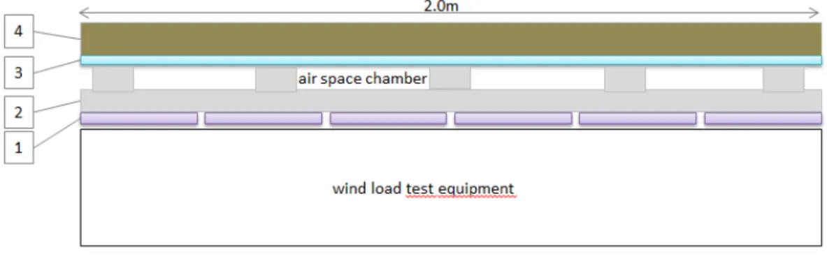
inside to the outside of the specimen, to reproduce the air flow in a ventilated cladding system (air space chamber). The substrate can be composed of a polycarbonate plate, whose thickness must be calculated in the function of the vent load. The open joints between the polycarbonate plate and metal
profiles also contribute to the air flow. The outer face of the specimen must be placed in front of the test chamber where the loads will be applied. Figure 3 shows a generic specimen scheme to be assembled in wind load test equipment.
Table 4 – Proposed Soft and Hard Impact Criteria
Category IV* Category III* Category II* Category I*
Impact 1 J (hard impact – service
load)
cladding element not
cracked(1) --- --- ---
Impact 3 J (hard impact – service load)
--- element not cladding
cracked(1) --- ---
Impact 10 J (hard impact –
rupture load) --- ---
Non-occurrence of falling off of any
components; admitting, however, cracking of the cladding element, as long as it is possible for its replacement and replenishment. Cladding components do not present sharp or cutting edges.
Impact 60 J (soft impact–
service loads)
---- --- Occurrence of failures, such as cracks, breaks,permanent deformationsamong others, in the cladding kit are not admitted
Impact 300 J (soft impact –
rupture loads) --- ---
Non-occurrence of falling off of any components, admitting, however, cracking of the cladding element, as long as it is possible for its replacement and replenishment. Deformations are permitted in parts of the subframe because corrective maintenance allows it to return to the original state before the impact.
Cladding components do not present sharp or cutting edges.
---
Impact 400 J (soft impact –
rupture loads) --- -- --- Item 300 J
Note: (1)The t est result is assessed as being “ cracked” if circul ar cracking penet rat ing is observed; and *Cat egory set on
Figure 3 – Generic specimen scheme in the plant to be assembled in the wind load test equipment
The specimen tested was designed and executed taking into account the cladding kit of the case study, which is formed with ceramic elements mechanically fastened to the subframe fixed to the main building structure and wall (substrate) through anchors.
The cladding elements of the specimen constitute ceramic plates that have variable widths (150 mm to 300 m) and lengths (1185 mm to 1415 mm). The subframe is made of aluminum profiles with the following dimensions: 50 × 73 × 50 × 73 × 4. 76 mm. The fixing devices are also made of aluminum according to the design specifications. EPDM profiles are placed between the metal parts and ceramic to absorb possible differences of motion/vibration between them. The substrate specimen is composed of a 10-mm thick polycarbonate plate structured by metal profiles. Figure 4 illustrates the specimen assembled for testing the wind load resistance and drainability. Next, the test was performed considering 2210 Pa as rupture load, 1480 Pa as service load, pressure, and suction, and one building of 90 m height situated in the city of São Paulo (Class IV, according to NBR 6123 (ABNT, 1988)). Table 5 lists the test results for pressure loads and Table 6 presents those for the suction loads.
From the analysis of the test procedure and results, it can be concluded that the method proposed is adequate and feasible to perform, highlighting that the specimen was assembled simulating the reality and tests were also performed to simulate real loads, in the case, considering the Brazilian wind load standard, NBR 6123 (ABNT, 1988). The test results of this specimen were satisfactory because no fault (e.g. excessive deflection, cracks or breaks) was observed.
Soft impact resistance (60 J and 400 J)
The criteria to evaluate the tests are based on Table 4.
The specimen must be mounted at one-floor height and at least 3.0 m length.
The substrate is the main difference between the wind test specimen and impact test specimen, which is formed by the wall (masonry or other, depends on the real project). Figure 5 shows a generic specimen scheme to be assembled for performing impact load test.
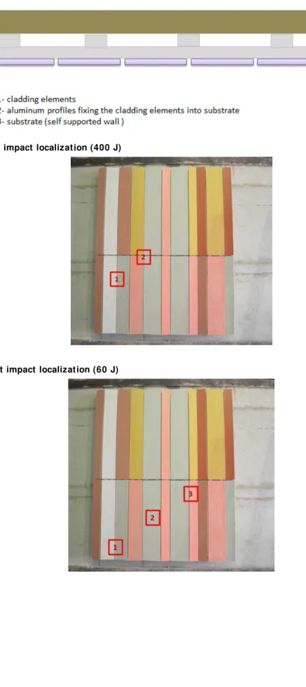
The impact energies (300 J and 400 J) are carried out with a bag weighing 40 kg, from a height of 0.75 m to 1.0 m. Such tests must be carried out in those regions where the cladding is installed at ground level or where there is easy access to the public. This test must be carried out in two points on the cladding kit: point 1 – between the vertical joints, point 2 – in the horizontal joint, in the region where the four cladding elements join each other (Figure 6).
The impacts of 60 J must be assessed at three points on the cladding element: point 1 – on the bottom edge, near to vertical joints, point 2 – on the center of the cladding element; and point 3- on the top edge of the cladding elements (Figure 7).
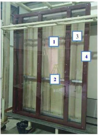
Figure 4 – Back area of specimen 1 (specimen placed to the wind pressure equipment )
Note:
1. back area of ceramic pl at e;
2. al uminum prof il es where t he ceramic pl at e is f ixing; 3. subst rat e composed of pol ycarbonat e pl at e; and 4. met al prof iles t hat st ruct ured t he subst rat e.
Table 5 – Wind pressure test results
Percentage of load Load (Pa) Deflection (mm) Observations
0 0 0,00 None reported
30% 444 0,32 None reported
0 0 0,00 None reported
60% 888 0,65 None reported
0 0 0,00 None reported
100% 1480 1,20 None reported
0 0 0,07 None reported
Rupture load 1 2210 None reported
Rupture load 2 2210 None reported
Table 6 – Wind suction test results
Percentage of load Percentage of load (Pa) Deflection (mm) Observations
0 0 0,00 None reported
30% 444 0,33 None reported
0 0 0,00 None reported
60% 888 0,70 None reported
0 0 0,00 None reported
100% 1480 1,24 None reported
0 0 0,07 None reported
Rupture load 1 2210 None reported
Figure 5 – Generic specimen scheme in the plant to be assembled for performing impact load tests
Figure 6- Soft impact localization (400 J)
Figure 8 – Front of the specimen 2 (cladding system) fixed to masonry
Note:
1. masonry (subst rat e); and 2. ceramic pl at es.
Figure 9 – Back of the specimen 2 (reinforced ceramic plates)
Note:
3. subf rame of t he al uminum prof iles;
4. EPDM prof il es bet ween t he met al and t he ceramic part s; and 5. al uminum composit e reinf orcing t he ceramic pl at es.
Tables 7 and 8 summarize the test results of the soft body impact of 400 J and 60 J. Both tests were performed considering the cladding on the ground floor, with reinforcement of aluminum plate on the back of ceramic plates.
By analyzing the test procedure and results, it is possible to conclude that the method proposed is adequate and feasible to perform, and the impact resistance criteria proposed can be possibly reached. In addition, the tests results are satisfactory because the occurrences did not affect the cladding performance, according to Table 3.
For others floors, the tests were not performed without reinforcing the ceramic elements, and so it was not possible to affirm that the cladding supported the soft impact resistance, even for 60 J.
Hard impact
Table 7 –Test results of soft body impact – 400 J
Impact localization Energy (J) Impact nº Occurrences
1 400 1 Breakage of thewithout falling off of any of the parts of the ceramic plate at the impact point, system
2 400 2 None reported
Table 8 – Test results of soft body impact – 60 J
Impact localization Energy (Joule) Impact nº Occurrences
1 60 1 None reported
2 60 2 None reported
3 60 3 Deformation of one part of the cladding fixation (Figure 7)
Figure 10 - Localization of the hard impact points (10 J)
The impact energy (10 J) is carried out with a steel ball weighing 1 kg and from a height of 1.0 m. Table 9 summarizes the hard body impact test results. This test was also executed considering the cladding on the ground floor with reinforcement of aluminum plate on the back of the ceramic.
Therefore, it is proper to assume the same conclusion for the soft and hard body tests, relating to the test procedure and results.
Drainability
The drainability test must be performed according to the watertightness test of NBR 10821-3 (ABNT, 2011b), considering the water pressure to be compatible with the classification of wind speed (according to NBR 6123, 1988) and with the height of the building. The specimen tested are the same as those used in the wind load tests. The aim of this test is to measure the water that reaches the
substrate or remains in the cladding inner, i.e., to quantify the water that was not drained out. Next, two moments were measured:
(a) immediately after the end of the test; and (b) 24 h after the end of the test, allowing the capture of the residual water remaining on the substrate or in other localizations.
It was also necessary to mount a device to capture the water that reaches the substrate (polycarbonate, in this case). The device consisted of troughs positioned in the metal structure of the specimen, hoses, a pipe collector, and a container for measuring the amount of water, as shown in Figure 11.
Then, for the test conducted on the specimen, a pressure of 296 Pa (20% of the service load pressure) was considered at 90 m height of the building situated at São Paulo (Class IV, according
1
2
3
4
to NBR 6123 (ABNT, 1988)). Table 10 summarizes the drainability test results.
The content of water that reaches the substrate is low in relation to the total water sprinkled, suggesting that if the design considers the ETAG considerations (minimum 20-mm thick air space
and ventilation openings at the base point and a roof edge with cross-sections of at least 50 cm2 per linear meter), there exists a possibility of performing drainability analysis based on the design, even in Brazil. However, it is considered necessary that the largest database of drainability test results be used for validating this hypothesis.
Table 9 – Test results of hard body impact - 10J
Impact
localization Energy (J) Occurrences
1
10
Fissure
2 Fissure
3 inner surface (back of the ceramic), without falling of any pieces or parts Sinking on the outer surface of the ceramic, and small fissure on the
4 Localized cracking*
5 Fissure without falling of any pieces/parts
Note: *resul t not considered because t he impact was appl ied on t he edge, not respect ing ETAG 034 Guidel ines.
Figure 11 – Device for collect ing water in the drainability test
Not es:
1. subst rat e composed of polycarbonat e pl at e; 2. t roughs horizont all y posit ioned; and 3. pipe col lect or.
Table 10 – Drainability test results
Sprinkling of water per nozzle (L/min)
Quanti ty of nozzle
Test Time (min)
Total water sprinkled
(L)
Water captured
during the test+
water uncaught¹ (L)
Relation between water sprinkled and water captured (%)
2 4 15 120 0,5 0,4
Conclusions
The ventilated cladding system has the potential to contribute to the façade watertightness, although this criterion must be satisfied by the entire façade and not just by the cladding system. However, the cladding has specific performance requirements and criteria to comply with, which justify this research work.
The proposed criteria and tests methods were feasible on the basis of the tests performed and obtained results. However, while conducting the tests, reproducibility of the cladding specimen must be analyzed corresponding to real design to avoid false analysis and inaccurate results. The specimen must be so assembled to always simulate the reality and the tests must be performed for simulating the real loads.
In future studies, we recommend performing soft-body and hard-soft-body tests in reference to the cladding elements without reinforcements (in this study aluminum plates were glued to the ceramic plates) and drainability tests while varying the thickness of the air space.
In regard to the drainability tests, to consolidate the test methods, the rate of 5% must be sustained in all the performed tests considering air space variation in cladding and fixing devices. Drainability performance contributes to the specification of the waterproof products used on the substrate (wall). Other tests, such as protection against noise, safety in case of fire, and aspects of durability and serviceability shall be performed in future studies. Considering the durability of the required systems, tests categorized as accelerated aging, natural aging, moisture chamber, and salt spray may be performed to estimate the cladding elements, subframe, and fixings performances. The data so obtained will provide guidance to formulate preventive maintenance activities of the cladding system.
References
AMERICAN SOCIETY FOR TESTING AND MATERIALS. ASTM E 283: standard test
method for determining rate of air leakage through exterior Windows, curtain walls, and doors under specified pressure differences across the specimen. Philadelphia, 2012.
AMERICAN SOCIETY FOR TESTING AND MATERIALS. ASTM E 330: standard test
method for structural performance of exterior Windows, doors, skylights and curtain walls by uniform static air pressure difference. Philadelphia, 2014.
AMERICAN SOCIETY FOR TESTING AND MATERIALS. ASTM E 331: standard test
method for water penetration of exterior Windows, skylights, doors, and curtain walls by uniform static air pressure difference. Philadelphia, 2009. ARCO. Fachadas Ventiladas no Mercado Brasileiro. Revista Finestra, v. 77, nov. 2012. Available on:
<https://arcoweb.com.br/finestra/tecnologia/tecnol ogia---especial-fachadas-fachadas-ventiladas>. Acess in: 01 apr. 2016.
ASSOCIAÇÃO BRASILEIRA DE NORMAS TÉCNICAS. NBR 10821: esquadrias para
edificações: parte 2: esquadrias externas: requisitos e classificação. Rio de Janeiro, 2011a.
ASSOCIAÇÃO BRASILEIRA DE NORMAS TÉCNICAS. NBR 10821: esquadrias para
edificações: parte 3: esquadrias externas e internas: métodos de ensaio. Rio de Janeiro, 2011b.
ASSOCIAÇÃO BRASILEIRA DE NORMAS TÉCNICAS. NBR 14762: dimensionamento de estruturas de aço constituídas por perfis formados a frio. Rio de Janeiro, 2010.
ASSOCIAÇÃO BRASILEIRA DE NORMAS TÉCNICAS. NBR 14827: chumbadores instalados
em elementos de concreto ou alvenaria: determinação da resistência à tração e ao cisalhamento. Rio de Janeiro, 2002a.
ASSOCIAÇÃO BRASILEIRA DE NORMAS TÉCNICAS. NBR 14918: chumbadores
mecânicos pós-instalados em concreto: avaliação de desempenho. Rio de Janeiro, 2002b.
ASSOCIAÇÃO BRASILEIRA DE NORMAS TÉCNICAS. NBR 15575: edificações
habitacionais: desempenho. Rio de Janeiro, 2013. ASSOCIAÇÃO BRASILEIRA DE NORMAS TÉCNICAS. NBR 6123: forças devidas ao vento em edificações: procedimento. Rio de Janeiro, 1988.
ASSOCIAÇÃO BRASILEIRA DE NORMAS TÉCNICAS. NBR 8800: projetos de estruturas de
aço e de estruturas mistas de aço e concreto de edifícios. Rio de Janeiro, 2008.
BECERE O. H. Revestimentos de Ligantes
Sintéticos: proposta de métodos de ensaios para
avaliação de desempenho. São Paulo, 2007. Dissertação (Mestrado em Engenharia Civil) - Instituto de Pesquisas Tecnógicas, São Paulo, 2007.
EUROPEAN TECHNICAL APPROVAL
EUROPEAN TECHNICAL APPROVAL GUIDELINES. ETAG 020: plastic anchors for
multiple use in concrete and masonry for non-structural applications. Brussels, 2012c. EUROPEAN TECHNICAL APPROVAL GUIDELINES. ETAG 029: metal injection anchors for use in masonry. Brussels, 2013. EUROPEAN TECHNICAL APPROVAL GUIDELINES. ETAG 034: ventilated cladding kits comprising cladding components and associated fixings. Brussels, 2012a.
EUROPEAN TECHNICAL ASSESSMENT. ETA
14/041: external wall claddings in ventilated
façade. Barcelona, 2014.
KUMAR, K. S., STATHOPOULOS, T., WISSE, J. A. Field Measurement Data of Wind Loads on Raincreen Walls. Journal of Wind Engineering
and Industrial Aerodynamics, v. 91, p. 1401–
1417, 2003.
LANGMANS, J.; ROELS, S. Experimental Analysis of Cavity Ventilation Behind Rainscreen Cladding Systems: a comparison of four
measuring techniques. Building and
Environment, v. 87, fev, 2015.
MACHADO, A. L. A. Diretrizes de Projeto Para Revestimentos Não Aderidos de Fachada
Constituídos de Placas Cerâmicas Extrudadas.
São Paulo, 2012. Dissertação (Mestrado em Engenharia Civil) - Instituto de Pesquisas Tecnológicas, São Paulo, 2012.
MARINOSCI, C.; SEMPRINI, G.; MORINI, G. L. Experimental Analysis of the Summer Thermal Performances of a Naturally Ventilated Rainscreen Façade Building. Energy and Buildings, v. 72, p. 280–287, 2014.
PATÓN, V. El Nascimiento de Uma Técnica.
Tectónica Cerramientos Pesados: Aplacados y
Panales – Envolventes (II). Barcelona, v. 2, p.
4-11, 1995.
PIANO, R. Fachada do IRCAM Institut de Recherche et Coordination
Acoustique/Musique. Available:
<http://www.rpbw.com/project/12/ircam>. Acess in: 23 nov. 2016.
RESENDE, M. M.; BARROS, M. M. S. B.; MEDEIROS, J. S. A Influência da Manutenção na Durabilidade dos Revestimentos de Fachada de Edifícios. In: WORKSHOP SOBRE
DURABILIDADE DAS CONSTRUÇÕES, 2., São José dos Campos, 2001. Anais... São José dos Campos, 2001.
RIBEIRO, F. A.; BARROS, M. M. S. B. Juntas de Movimentação em Revestimentos Cerâmicos
de Fachadas. São Paulo: PINI, 2010.
ROUSSEAU, M. Z.; POIRIER, G. F.; BROWN, W. C. Pressure Equalization in Rainscreen Wall Systems. Construction Technology Updates no. 17. Institute for Research in Construction, National Research Concil of Canada, 1998.
SANJUAN, C. et al. Energy Performance of an Open-Joint Ventilated Façade Compared With a Conventional Sealed Cavity Façade. Solar
Energy, v. 85, n. 9, p. 1851-1863, 2011.
SIQUEIRA JÚNIOR, A. A. Tecnologia de
Fachada-Cortina Com Placas de Grês
Porcelanato. São Paulo, 2003. Dissertação
(Mestrado em Engenharia Civil) - Escola
Politécnica, Universidade de São Paulo, São Paulo, 2003.
STRAUBE, J.; FINCH, G. Ventilated Wall
Claddings: review, field performance, and
hygrothermal modeling. Research Report – 0906, 2009. Available on: <http://buildingscience.com>. Acess in: 15 apr. 2016.
TRECHSEL, H. R.; BOMBERG, M. T. Moisture
Control in Buildings: the key factor in mold
prevention. Baltimore, 2009.
VEDOVELLO, C. A. S. Gestão de Projetos de
Fachadas. São Paulo, 2012. Dissertação
(Mestrado em Engenharia Civil) - Escola
Luiz Fernando Batista da Silva
Cent ro Tecnológico do Ambient e Const ruído, Diret oria de Operações e Negócios | Inst it ut o de Pesquisas Tecnol ógicas do Est ado de São Paul o | Av. Prof . Almeida Prado, 532, Cidade Universit ária Armando de Salles Oliveira, But ant ã | São Paulo - SP – Brasil | CEP 05508-901 | Caixa Post al 0141 | Tel. : (11) 3767-4556 | E-mail: lf ernando@ipt . br
Ercio Thomaz
Cent ro Tecnológico do Ambient e Const ruído, Diret oria de Operações e Negócios | Inst it ut o de Pesquisas Tecnol ógicas do Est ado de São Paul o | E-mail: et homaz@ipt . br
Luciana Alves de Oliveira
Cent ro Tecnológico do Ambient e Const ruído, Diret oria de Operações e Negócios | Inst it ut o de Pesquisas Tecnol ógicas do Est ado de São Paul o | E-mail: luciana@ipt . br
Revist a Ambient e Const r uído
Associação Nacional de Tecnol ogia do Ambient e Const ruído Av. Osval do Aranha, 99 - 3º andar, Cent ro
Port o Al egre – RS - Brasil CEP 90035-190 Telef one: +55 (51) 3308-4084
Fax: +55 (51) 3308-4054 www. seer. uf rgs. br/ ambient econst ruido
E-mail : ambient econst ruido@uf rgs. br