Nonlinear analysis of concrete structures using GFEM
enrichment strategy with a microplane constitutive model
Análise não linear de estruturas de concreto usando a
estratégia de enriquecimento MEFG com um modelo
constitutivo de microplanos
a Instituto Federal de Santa Catarina (IFSC), São Carlos, SC, Brasil;
b Universidade Federal de Minas Gerais (UFMG), Programa de Pós-Graduação em Engenharia de Estruturas (PROPEEs), Belo Horizonte, MG, Brasil.
Received: 09 Mar 2017 • Accepted: 06 Nov 2017 • Available Online:
A. R. V. WOLENSKI a
anderson.wolenski@ifsc.edu.br
A. B. MONTEIRO b
ane.lize.eng@gmail.com
S. S. PENNA b
spenna@dees.ufmg.br
R. L. S. PITANGUEIRA b
roque@dees.ufmg.br
F. B. BARROS b
felicio@dees.ufmg.br
Abstract
Resumo
One of the most widespread methods to the nonlinear analysis of structures is the Finite Element Method (FEM). However, there are phenomena whose behavior is not satisfactorily simulated by the standard FEM and this fact has quickened the development of new strategies such as the Generalized Finite Element Method (GFEM), understood as a variation of the FEM. In parallel, nonlinear analysis of concrete structures requires the use of constitutive models that represents the nucleation and propagation of cracks. In this paper it is used an anisotropic constitutive model, based on the microplane theory, which is able to represent the behavior of concrete structures, together with the GFEM approach. These re-sources are incorporated on the INSANE system (INteractive Structural ANalysis Environment), used in the numerical simulations presented here to demonstrate the feasibility of using the GFEM enrichment strategy, in the nonlinear analysis of concrete structures, with validation made from comparisons with experimental results available in the literature.
Keywords: INSANE system, physically nonlinear analysis, microplane theory.
Um dos métodos numéricos mais difundidos para a análise não linear de estruturas é o Método dos Elementos Finitos (MEF). No entanto, há fenômenos cujo comportamento não é satisfatoriamente representado pela forma convencional do MEF e isso tem estimulado o desenvolvimen-to de novas estratégias, como o Médesenvolvimen-todo dos Elemendesenvolvimen-tos Finidesenvolvimen-tos Generalizados (MEFG), entendido como uma variação no MEF. Em paralelo, a análise não linear de estruturas de concreto exige o uso de modelos constitutivos que representem a nucleação e propagação de trincas. Neste trabalho, é usado um modelo constitutivo anisotrópico, baseado na teoria de microplanos, capaz de representar o comportamento de estruturas de concreto, juntamente com a aproximação MEFG. Tais recursos estão incorporados no sistema INSANE (INteractive Structural ANalysis Envi-ronment), usado nas simulações numéricas aqui apresentadas com objetivo de demonstrar a viabilidade do uso da estratégia de enriquecimento do MEFG, na análise não linear de estruturas de concreto, com validação realizada a partir de comparações com resultados experimentais disponíveis na literatura.
1. Introduction
Several engineering problems can be described using partial differ-ential equations relating field variables inside a particular domain. To obtain reasonable solutions it is used some numerical method since such problems have complex geometry and boundary conditions. In this context, it was developed the Finite Element Method (FEM), which is an efficient numerical tool to solve boundary value problems. Although the FEM is a quite consolidated numerical technique in the study of several structural engineering problems, it presents some limitations related specially to the description of phenomena such as crack and damage propagation and large deformations. The nature of these phenomena leads to the modification of the mesh in a very costly process.
Nowadays it is impossible to design innovative structures without FEM and the use of computational programs based on this method became easier due to the development of pre-processor and post-processor tools that provide interactive graphics resources. Nonetheless, there are phenomena whose behavior cannot be satisfactorily described by conventional FEM and this fact has mo-tivated the development of new strategies. Problems subjected to large deformations and to crack and damage propagation require modifications in discretization of the structure (remeshing) and methods such as the Generalized Finite Element Method (GFEM) have been developed to solve these issues.
The GFEM (Melenk and Babuška [1]; Duarte et al. [2]) can be considered as originated from the so-called meshless methods proposed in the 1990s. In spite of its theoretical bases be well es-tablished, there is an extensive area of research and of numerical experimentation to be investigated. According to Barros et al. [3], GFEM is formulated in a way that the numerical simulation guar-antees certain independence of the mesh of finite elements. The relative mesh independence can be observed by the possibility of introducing special functions on the numerical approximation, with-out modifying the mesh, and by the relative insensitivity to angular distortion of the elements.
The objective of this paper is to evaluate the use of linear and quadratic polynomial enrichment functions of the GFEM approach in nonlinear problems of concrete structures. The obtained results with GFEM and FEM strategies combined with an anisotropic constitutive model, based on the microplane theory, will be com-pared to each other. The validation of the results obtained with the GFEM approach is made through comparisons with experimental responses of concrete beams subjected to the three-point bending (Petersson [4]) and of L-shaped panel by Winkler et al. [5].
The outline of the paper is as follows. A brief explanation of GFEM is presented in Section 2. The Microplane Theory for anisotropic constitutive models, based in the formulation of Leukart [6] and used in all simulations presented here, it is discussed in Section 3. In the Section 4, numerical examples are presented, and Section 5 is devoted to concluding remarks and discussion.
2. A summary explanation of GFEM
Initially proposed by Melenk [7], the GFEM has the important char-acteristic of enriching the space of approximations originally con-structed to the FEM with the introduction of special functions. Such
functions are able to reproduce phenomena observed in specific regions of the analyzed domain.
Results presented by Strouboulis et al. [8] and Duarte and Oden [2] showed that the enrichment strategy with functions that reflect the local nature of the solution contributed to improve the quality of the approximation, with the introduction of a relatively small number of degrees of freedom.
In GFEM, the approximation functions are constructed as in the hp-Cloud Method (Duarte and Oden [9]; [10]), where cloud points are distributed arbitrarily and without links to each other, whereas in the GFEM a finite element is adopted for nodal positioning and structuring of the shape functions.
The use of the Partition of Unity (PU) functions (based on the method of Melenk and Babuška [1]) over the mesh of finite ele-ments and its enrichment carried out in a way analogous to the hp-Cloud Method make GFEM an unconventional approach of the FEM and allow it to be correlated with the Meshless Methods. The strategy used in GFEM consists of enriching PU functions to define alternative shape functions. The standard functions of FEM (such as Lagrangian functions) facilitate the application of the GFEM and, differently from the meshless methods, directly verify the boundary conditions (Barros et al. [3]).
In the GFEM the PU functions are constructed in regions called clouds ωj. However, these clouds differ from those of the Meshless Methods and they are constituted by sets of finite elements shar -ing the nodal points xj, according to Figure 1 (Nj (x) represents the PU functions).
For example, in ℝ1 the PU is obtained from linear functions associ-ated with each cloud.
(1)
The enrichment functions are multiplied by the original PU, guaran-teeing the improvement of the quality of the approximation. Aiming to clarify this strategy, it is considered a conventional mesh of finite element defined from a set of n nodal points , according to Figure 2(a), in ℝ2. It is defined a patch or cloud ω
j formed by all elements that share the nodal point xj.
The set of interpolative Lagrangian functions associated with the node xj defines the function Nj (x) whose support corresponds to the region ωj, according to Figure 2(b).
A set of enrichment functions, Ij, named local approximation
func-Figure 1
tions, is composed by qj linearly independent functions defined to each node xj with support on the cloud ωj:
(2)
At the end of the process, the shape functions ϕji (x) of GFEM, shown on Figure 3(b), associated with the node xj are built through the enrichment of the PU functions by the components of the set Ij. Thus, according to equation (3), ϕji (x) (Figure 3(b)) can be ob-tained by the product between the basic functions that form the PU (Figure 2b) and the enrichment functions (Figure 3a).
(3)
The functions in equation (2) can be polynomial or not depending on the problem analyzed. The use of the functions of FEM as the PU simplifies the implementation and avoids, according to Barros et al.
[3], problems related to the numerical integration and to the imposi-tion of the boundary condiimposi-tions. Thus, a generic approximaimposi-tion is obtained by the following linear combination of the shape functions:
(4)
where uj and bji are nodal parameters associated with standard (Nj) and GFEM (Nj (x) × Lji (x)) shape functions, respectively. Furthermore, aiming to minimize round-off errors, Duarte et al. [2] suggest that a transformation should be performed over the Lji (x) functions, if they are of polynomial type. In such case, the coordi-nate x is replaced as follows:
(5)
in which hj is the diameter of the smallest circle that circumscribed the cloud ωj.
Figure 2
Strategy of enrichment of the cloud
ω
j(Barros
et al.
[3])
A
Cloud wjB
Partition of unity functionFigure 3
Strategy of enrichment of the cloud
ω
j(Barros
et al.
[3])
It is obtained the product function that presents the characteristics of the local approximation function while inherits the compact support of the PU. Among some advantages of the GFEM when compared to the standard FEM, it is possible to mention the enrichment of the ap-proximations to treat specific problems with functions specially defined to this purpose. Thus, the enrichment can be performed in regions of interest in which the behavior is more pronounced without elevating computationally the analysis.
3. Anisotropic constitutive models based
on the microplane theory
The adaptation of Microplane Theory to concrete structures oc-curred from the association between solid structure of the hetero-geneous material (cementitious matrix with aggregates of different particle sizes) and the existence of multiple plans of discontinui-ties, positioned at the interfaces of its grains.
This association is quite pertinent because of the occurrence and
propagation of microcracks in different directions that lead to an inelastic response of the material. Such propagation generally oc-curs at the existing interface between the cementitious matrix and the aggregates, as shown in Figure 4.
The formulations of the Microplane Models generally follow three main steps: the projection of the strains in the microplanes, the definition of the constitutive laws and the homogenization process, as can be seen in Figure 5.
The model proposed by Leukart [6], and used in all simulations of this paper adopts: (step 1) a decomposition of the macroscopic strain tensor into its volumetric (εV) and deviatoric (εD) components (V-D split); (step 2) that the damage process is the main dissipation mechanism which describes the degradation on the material and that the degradation is evaluated through a single equivalent strain combined with a single damage law; (step 3) that the free energy on the microplanes exists and its integral over all microplanes is equal to the macroscopic free energy of Helmholtz.
Wolenski [11] generalizes the computational implementation of
Figure 4
Association between the plans of discontinuities and the solid concrete microstructure
Figure 5
Leukart [6] proposition, in order to allow any microplane equivalent strain measure and any damage law. Such an improvement has been implemented in the context of the Unified Computational En-vironment, proposed by Penna [12] and Gori et al. [13], on the IN-SANE. This system has been expanded by Alves et al. [14] with the enclosing the standard version of GFEM formulation with minimum impact in the code structure. Based on this expansion an object oriented design of GFEM to physically nonlinear analysis has been extended by Monteiro et al. [15], being used in all simulations of this paper. Further details about the INSANE system can be found
in INSANE Project [16].
The numerical simulations presented in this paper use one of the options of the unified environment for microplane models of the
INSANE system. Specifically, the simulations uses
volumetric-deviatoric strain split proposed by Leukart [6] and the equivalent strain defined by de Vree et al. [17], according to:
(6)
where εV is volumetric part of the strain tensor, ε_p is the p compo-nent of the deviatoric strain tensor, k1 and k2 are material param-eters that relate to tensile and compression strength of concrete and ηVree is equivalent strain measure adopted on the different damage laws such as the exponential, polynomial, and linear laws defined by equations (7), (8) and (9), respectively:
(7)
(8)
(9)
where dmic is the damage measure, κ is the current equivalent strain (equation 6), κ0 and κu are material parameters that specifies a limit for κ referring, respectively, to the beginning and end of the damage process, while E0 is the Young’s modulus.
The parameter α is the maximum material degradation, β is the parameter governing the shape of the post-peak branch, fe is the equivalent stress related to the material strength limit. They are dimensionless numerical parameters of the constitu-tive model.
These formulations are detailed in Wolenski [11] and they were ad-opted on the numerical simulations presented in Wolenski et al. [18].
4. Numerical simulations
In this section some numerical simulations are presented aiming to illustrate and to validate discussions about the use of the anisotro-pic constitutive model, which is able to represent the behavior of concrete structures together with GFEM approach.
These simulations also allow illustrating the use of the GFEM ac-cording to the characteristics of the analyzed problem, providing different ways of investigating the problem and performing the relevant numerical simulations, with the choice of the enrichment functions, the nodes to be enriched, the combination of different functions in the same problem, among other possibilities.
For all simulations, the approximation functions of enrichment, with monomials expressed in coordinates x and y, are defined by:
nP
0 (no enrichment):
(10)
nP1 (linear enrichment):
(11)
nP
2 (quadratic enrichment):
(12)
The solution procedure to nonlinear problems described here is the Newton-Raphson Algorithm and other characteristics of each simulation are detailed in the respective item. The geom-etry and boundary conditions are illustrated throughout each problem, since the aiming is to use distinct types of elements combined with different enrichment strategies. The results ob-tained in the simulations are compared with the experimental ones presented in literature.
4.1 Three-point bending
Petersson [4] experimentally studied concrete beams subjected to three-point bending. The experimental results obtained by the author were used by Monteiro at al. [15] and extended here to compare with the numerical results of the simulations performed with GFEM and FEM approaches.
Table 1
Material parameters based on the experimental results obtained by Petersson [4]
Young's modulus Poisson ratio Uniaxial yield stress Fracture energy
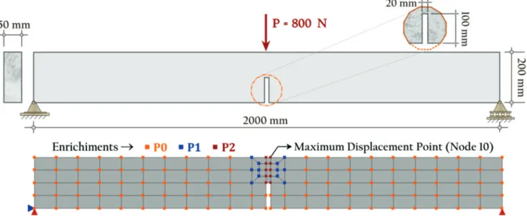
The material parameters obtained experimentally by Petersson [4] and adopted to the numerical simulations are shown in Table 1. Figure 6 depicts the geometric data of the beam and the mesh of
115 four-node quadrilaterals elements (with 4×4 Gauss Quadra-ture). The numerical simulations are performed with the convention-al FEM (260 degrees of freedom and with no enrichment - P0) and with GFEM applying linear (P1) and quadratic (P2 enrichment func-tions highlighted at the nodes of the figure (384 degrees of freedom). Table 2 presents the numerical parameters to the different dam-age laws and they are grouped according to the equivalent strain defined by de Vree et al. [17].
In possession of such parameters, the nonlinear analyses have been performed under plane stress conditions and with the adop-tion of the generalized displacement control method (Yang and Shieh [19]), with initial load factor equal to 0,020, tolerance to convergence of 1 ×10⁻⁴(×100%) = 0,010% in relation to the norm of the incremental displacements vector, a reference load of P = 800N and a secant approximation to the constitutive tensor. Figures 7, 8 and 9 show the equilibrium paths, describing the vertical dis-placement of the node 10, together with the experimental results obtained by Petersson [4], using different damage laws, according to equations
Figure 6
Three-point bending: geometry and mesh
Table 2
Parameters adopted to the simulations
for different laws
Exponential damage law
α = 0,960 β = 500,00 κ0 = 0,0002
Polynomial damage law
fe = 5,95 E0 = 30000,00 κ0 = 0,000385
Linear damage law
κu = 0,00460 κ0 = 0,000190
Figure 7
(7), (8) and (9). The equilibrium path GFEM-P1+P2 refers to the trajectory obtained using GFEM approach and the equilibrium path denominated FEM-P0 refers to the trajectory obtained by the FEM approach.
From Figures 7, 8 and 9 it is possible to observe that the GFEM approach provided stability to the equilibrium paths and agreement with those experimentally obtained by Petersson [4]. The enrich-ment strategy improved the solution around the region where the nonlinear phenomenon happens and it does not require modifica-tion in the neighboring elements of that region, as it would be the case to FEM if selective h or p refinements are applied.
Additionally, it is recognized that the standard FEM analysis
pre-sented a worse description of the equilibrium path due to the poorer discretization adopted. A finer mesh around the notch could provide a better solution. In such case, special attention would be required to avoid problems related to the transition from the bigger to the smaller elements. Another strategy could be using higher order elements on that same region, but the inclusion of irregular nodes lead to a constrained approximation.
Figure 10 shows the number of iterations to achieve equilibrium for each load step. This figure allows inferring that the number of iterations GFEM does not significantly vary, being smaller in some situations and greater in others.
Figure 8
Simulations using a polynomial damage law (equation 8)
Figure 9
Figure 10
Number of iterations per load step: (a) Exponential; (b) Linear and (c) Polynomial damage laws to FEM
versus
GFEM approach
A
B
4.2 L-shaped panel
The numerical simulations of a L-shaped panel are presented to discuss the influence of mesh refinement and enrichment functions
on the numerical response performed with GFEMandFEM ap-proaches, as well as the use of the Microplane Constitutive Model by Leukart [6].
Such simulations are compared with the result presented by Winkler et al. [5] that performed experimental tests on concrete panel, according to the geometry and boundary conditions pre-sented in Figure 11(a).
The numerical simulations are performed with triangular finite ele -ments (T3) in the following way: conventional FEM with 410 ele-ments (Figure 11(c)) (476 degrees of freedom and with no enrich-ment - P0) and GFEM with 278 elements applying enrichments P1 in 142 nodes and P2 in 23 nodes from the center corner of the
Figure 11
L-shaped panel: (a) geometry and boundary conditions; (b) mesh for GFEM with enrichment functions;
(c) mesh for FEM with no enrichment
A
B
C
Table 3
Material parameters obtained by Winkler
et al.
[5]
Young's modulus Poisson ratio Uniaxial yield stress Fracture energy
E0 = 25850 MPa νc = 0,18 σt ≅ 2,70MPa Gf≅ 0,065 N/mm
Table 4
Parameters adopted for the simulation of the
L-Shaped panel
Exponential damage law
α = 0,960 β = 500,00 κ0 = 0,000152
Figure 12
Simulations for L-shaped panel by Winkler
et al.
[5] using the Microplane Model and an exponential
panel, as illustrated in Figure 11(b) (1082 degrees of freedom). It was adopted enrichment functions P2 for an area with a higher occurrence of damage, in order to achieve the same effect of mesh refinement via FEM in this region. A conventional FEM analysis (Figure 11(c)) was applied considering all nodes without enrichment (P0 ).
The material parameters experimentally obtained by Winkler et al.
[5] and adopted to the numerical simulations are shown in Table 3. From Table 3 it was possible to obtain the numerical parameters used in the simulations, according to Table 4.
In possession of such parameters, the nonlinear analyses have been performed under plane stress conditions and it is adopted generalized displacement control method, with initial load factor equal to 0,03, tolerance to convergence of 1 × 10⁻⁴ (×100%) = 0,010% in relation to the norm of the incremental displacements vector, reference load of q = 32 N/mm and a secant approximation to the constitutive tensor.
Figure 12 shows the numerical results of the displacement control point shown in Figure 11(a), together with the experimental results obtained by Winkler et al. [5].
Both results show good concordance with the experimental ones
obtained by Winkler et al. [5]. However, it is noted better stabil-ity along of the inelastic regime obtained with GFEM approach and the equilibrium path was closer to the experimental result than the equilibrium path obtained with standard FEM. Only the insertion of enrichment functions into the coarser mesh, without the need for refinement, was able to improve the result in rela-tion to the FEM.
To illustrate the evolution of panel degradation throughout the anal-ysis, the Figures 13 and 14 shows the damage for both meshes 1 (GFEM) and 2 (FEM), respectively.
These figures show that the propagation of damage represents the expected behavior, since the degradation begins in a concen-trated manner in the center of the panel and propagates horizon-tally along of the panel. In this sense, the mesh with a greater refinement presented a behavior slightly closer to that obtained by Winkler et al. [5], for the experimental and numerical cases, as illustrated in Figure 15.
The substitution of finite element mesh refinement by GFEM ap-proach proved to be efficient for the problem in question, indicating the flexibility and feasibility of this feature to the physically nonlin-ear analysis.
Figure 13
Variation of damage to an exponential function – mesh 1 (GFEM)
Figure 14
5. Final remarks
In this paper a summary of GFEM formulation and of the Anisotro-pic Constitutive Models, based in Microplane Theory, were made. It was analyzed a concrete beam subject a three-point bending and a L-Shaped Panel, and a computational framework for non-linear analysis by GFEM approach combined with the Microplane Constitutive Model was used.
The obtained results were compared with the experimental ones provided by Petersson [4] and Winkler et al. [5] and they showed good agreement in all simulations performed to different damage laws. It was possible to verify the versatility of the GFEM approach
in INSANEsystem because of the application of different
polyno-mial enrichment functions combined with different damage laws of the Microplane Model by Leukart [6].
In both simulations (Sections 4.1 and 4.2) the enrichment strat-egy under the GFEM approach provided stability to the equilibrium paths. The polynomial enrichment strategy provided by GFEM al-lows improving the quality of the approximation in a very simple and straightforward way, without overloading the analysis with a very refined mesh.
All the simulations demonstrated that GFEM are able to reproduce the results of FEM and even improve the solutions just applying enrich-ment functions in some nodes of the meshes, allowing varied analysis in which the refinement of the mesh (that can lead to numerically in-duced strain localization) is not necessary to achieve better solutions. New investigations can be performed aiming to verify the numeri-cal stability of GFEM to the nonlinear analysis, mainly when its ap-plication requires enrichments of higher order or a large number of finite elements. Additionally, it is possible to apply other constitutive models and also to apply the GFEM global-local implementation to nonlinear analysis, which is under development.
These aforementioned research themes are among the future works of our research group, aiming to empower the INSANE computational platform to solve wider range of the solid mechan-ics problems. Finally, a data set along within put files of this work can be found at https://doi.org/10.6084/m9.figshare.5505898 [20], in order to reproduce the results here presented.
6. Acknowledgements
The authors gratefully acknowledge the important support of the
Brazil-ian research agencies FAPEMIG (in Portuguese “Fundação de Ampa-ro à Pesquisa de Minas Gerais” - Grant APQ-02460-16) and of CNPq (in Portuguese “Conselho Nacional de Desenvolvimento Científico e Tecnológico” – Grants 308785/2017-2 and 308932/2016-1).
7. References
[1] MELENK, J. M. and BABUŠKA, I. The partition of unity finite element method: basic theory and applications. Computer Methods in Applied Mechanics and Engineering. v. 39, p. 289-314, 1996.
[2] DUARTE, C. A., BABUŠKA I., ODEN, J. T. Generalized Finite Element Methods for Three Dimensional Structural Mechanics Problems. Computers and Structures. v. 77, p. 215-232, 2000.
[3] BARROS, F. B., PROENÇA, S. P. B. and de BARCELLOS, C. S., 2004. On error estimator and p-adaptivity in the gen-eralized finite element method. Int. J. Numer. Methods Eng., vol. 60, pp. 2373–2398.
[4] PETERSSON, P. E. Crack growth and development of frac-ture zones in plain concrete and similar materials, Tech Re-port TVBM-1006, Lund Institute of Technology - Division of Building Materials, Lund, Sweden, 1981.
[5] WINKLER, B; HOFSTETTER, G.; LEHAR, H. Application of a constitutive model for concrete to the analysis of a precast segmental tunnel lining, International Journal for Numerical and Analytical Methods in Geomechanics. V. 25, p. 797-819, 2004. [6] LEUKART, M. Kombinierte Anisotrope Schädigung und Plas-tizität bei Kohäsiven Reibungsmaterialien. Ph.D. Thesis, Universität Stuttgart, German, 2005.
[7] MELENK, J. M., 1995. On Generalized Finite Element Meth-ods. Ph.D. Thesis, University of Maryland, College Park. [8] STROUBOULIS, T.; BABUŠKA, I.; COPPS, K. The design
and analysis of the Generalized finite element method. Com -puter Methods in Applied Mechanics and Engineering, v. 181, p. 43-69, 2000.
[9] DUARTE, C. A. and ODEN, J. T. Hp clouds – a meshless method to solve boundary-value Problem. Technical Report TICAM. University of Texas at Austin, 1995.
[10] DUARTE, C. A. and ODEN, J. T. An hp adaptative method using cloud. Computer Methods in Applied Mechanics and Engineering. v. 139, p. 237-262, 1996.
Figure 15
Damage pattern observed by Winkler
et al.
[5]: (a) experimental and (b) numerical
[11] WOLENSKI, A. R. V. Ambiente Teórico-Computacional Uni-ficado para Modelos Constitutivos: Inclusão de Modelo de Microplanos. Master’s Thesis. Universidade Federal de Minas Gerais (UFMG), Brazil, 2013.
[12] PENNA, S. S. Formulação Multipotencial para Modelos de Degradação Elástica: Unificação Teórica, Proposta de Novo Modelo, Implementação Computacional e Modelagem de Estruturas de Concreto. Ph.D. Thesis. Universidade Federal de Minas Gerais (UFMG), Brazil, 2011.
[13] GORI, L., PENNA, S. S., PITANGUEIRA, R. L. S. A com-putational framework for constitutive modelling. Computer & Structures, v. 187, p. 1-23, 2017.
[14] ALVES, P. D., BARROS F. B., PITANGUEIRA R. L. S. An ob-ject-oriented approach to the Generalized Finite Element Meth-od, Advances in Engineering Software. v. 59, p. 118, 2013. [15] MONTEIRO, A. B.; WOLENSKI, A. R. V.; PENNA, S. S.;
BARROS, F. B.; PITANGUEIRA, R. L. S. A computational framework for G/XFEM Material Nonlinear Analysis. Advanc-es in Engineering Software, (in prAdvanc-ess), 2017.
[16] INSANE Project. ‘http://www.insane.dees.ufmg.br/’ (Ac-cessed in October, 2017). The development code is avail-able at the Git repository URL https://git.insane.dees. ufmg. br/insane/insane.
[17] de VREE, J. H. P.; BREKELMANS, W. A. M.; van GILS, M. A. J. Comparison of nonlocal approaches in continuum dam-age mechanics. Computer & Structures, v. 55, p. 581-588, 1995.
[18] WOLENSKI, A. R. V.; de CASTRO, S. S.; PENNA, S. S.; PI-TANGUEIRA, R. L. S.; SILVA, B. V.; BARBOSA, M. P. Exper-imental and finite element analysis of bond-slip in reinforced concrete. IBRACON Structures and Materials Journal, v. 8, p. 787-799, 2015.
[19] YANG, Y. B. and SHIEH, M. S. Solution method for nonlin-ear problems with multiple critical points. AIAA Journal, v. 28 (12), p. 2110-2116, 1990.