UNIVERSIDADE DA BEIRA INTERIOR
Engenharia
CFD Analysis of the Combustion of Bio-Derived
Fuels in the CFM56-3 Combustor
Jonas Miguel Pires de Oliveira
Dissertação para a obtenção do Grau de Mestre em
Engenharia Aeronáutica
(Ciclo de estudos integrado)
Orientador: Prof. Doutor Francisco Miguel Ribeiro Proença Brójo
Dedication
To my beloved parents, João de Oliveira and Jacqueline de Oliveira whom without I would never be where I am now. Thank you for everything!
To my brothers, Steven and Christopher to whom I wish only the best for their future. For my family, whose affection and encouragement were my source of inspiration.
"The best way to predict your future is to create it"
Acknowledgements
A big thank you to my family who supported me unconditionally throughout these five years away from home. My love for you is beyond words!
There are not enough words to thank my supervisor, Professor Francisco Brójo, whom was always there to ensure that I was following the right path. Professor, you basically provided me every-thing that was needed to perform this study, starting with the negotiations with TAP; suggesting the scanning of the combustor; and lending your personal computer, in which the scanning of the model was held, and also in which most of the simulations were performed. I am forever grateful for the kind patience and encouragement which you always demonstrated, being key factors to making me prepare this project.
My deepest thanks to TAP for providing the combustor, which was the foundation of this work; and a special thanks to Eng. Joana Palmeiro for hosting our visit to TAP, and for also providing important information for the development of this study.
I would also like to acknowledge Olga Skvortsova, a member of Artec support team, for all of her kind advices to solve some persistent problems that rose during the scanning phase. I am profoundly grateful to CODI, and more especially Jennifer Faustino, for enabling that this hole project of reverse engineering could gain life, as they performed a 3D print of the model combustor and offered it to UBI. Moreover, thank you João Correia for first suggesting this, and for ensuring that all was done so that this could be performed.
A big thank you to my dear friend Robert Gonçalves, for not only being of good company during the first half of the preparation of this project, providing moments of laughter and comfort, but for also providing important tips during the CFD analysis; he was also responsible for my introduction to LATEX, which proved really useful in organizing this document.
I would like to thank Eng. Pedro Santos for reviewing this document, but above all, for being a good friend.
And last but not least, I wish to thank all of my friends from my hometown and those made in my academic life, especially Bryan, Jorge, Elvis, Ricardo, Alexandre, Francisco, Pedro and Gilberto, whom are truly a huge part of my life.
Resumo
Uma simulação CFD é realizada numa câmara de combustão do motor CFM56-3, usando como combustíveis Jet-A e uma mistura de biocombustíveis a 100%. É pretendido avaliar a viabilidade destes biocombustíveis num ponto de vista da combustão, ao analisar as emissões e a energia extraída quando estes combustíveis são injetados, a fim de que estes biocombustíveis possam ser considerados como uma possibilidade de futuros combustíveis para a aviação comercial. Os três biocombustíveis que foram considerados para este estudo, são extraídos de sementes da planta jatropha, de algas e de girassol. Devido à confidencialidade que reina entre as empresas de manufatura de turbinas a gás, é muito difícil obter o blueprint de qualquer parte de uma turbina a gás, e a câmara de combustão em estudo não foi exceção. Felizmente a TAP gentil-mente cedeu uma câmara de combustão ainda em serviço, na qual foi possível realizar um scan 3D, com recurso ao scanner pertencente à UBI, denominado de Spider da Artec Group. A partir deste modelo 3D, um ficheiro STL pôde ser exportado, e depois importado para o CATIA V5, que por sua vez foi o software escolhido para efetuar o CAD. Todas as partes da câmara de com-bustão relevantes para o estudo são representadas, onde estão incluídos os swirlers primário e secundário, os injetores de combustível, os orificios para arrefecimento, as paredes e o dome; apenas um quarto da câmara de combustão é usado para o estudo numérico devido à simetria existente, e devido ao facto que dos 20 injectores de combustível presentes, existem 4 em que é injetado uma mistura mais rica. A malha numérica é criada com recurso ao HELYX-OS, e o software comercial ANSYS Fluent 15.0 é usado para efetuar o estudo numérico. Devido à complexidade deste estudo, a atomização do combustível não é considerada. O modelo viscoso usado é o RSM; todas as entradas de ar, bem como os injetores de combustível são definidos como mass-flow inlets, e a saída da câmara de combustão é definida como um pressure-outlet. Os resultados finais estão razoalmente de acordo com os dados de referência apresentados pela ICAO, quando Jet-A é queimado, apresentando um erro no geral muito reduzido. Entre todos os combustíveis simulados, foi provado que aumentando a potência resultava num aumento de emissões N Ox e num decréscimo de U HC′s; contudo um comportamento inesperado de uma
redução de emissões CO com o aumento da potência, foi verificado. O biocombustível que apresentou os melhores resultados ao longo de todo o ciclo de potência da ICAO, com respeito às emissões N Ox, CO e U HC, foi o proveniente de girassol, uma vez que foi previsto valores
de emissões inferiores, quando comparados com os restantes combustíveis. O biocombustível proveniente de jatropha foi o que apresentou uma maior redução de emissões CO2,
represen-tando um decréscimo de 20% comparando com o de Jet-A, e a energia extraída representou um menor decréscimo de 6% quando comparado com o mesmo combustível. No geral pode ser concluído que os biocombustíveis estudados têm o potencial de substituir a querosene, e apesar de que um maior consumo é exigido aos biocombustíveis, de forma a produzir a mesma energia que Jet-A, uma redução significativa de emissões é prevista.
Palavras-chave
TAP; CFM56-3; Câmara de combustão; CATIA V5; HELYX-OS; CFD; ANSYS Fluent; Biocombustíveis; Emissões
Abstract
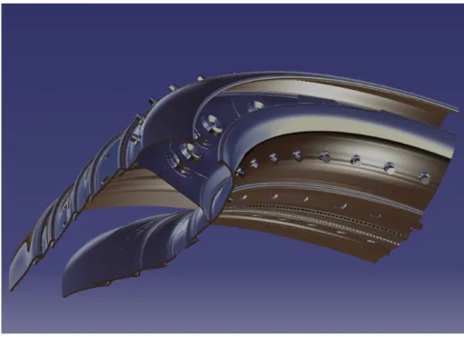
A CFD simulation of a CFM56-3 combustor burning Jet-A and a 100% blend of biofuels, is per-formed. It is intended to evaluate the viability of these biofuels in a combustion point of view, by analysing the emissions and the energy extracted when burning these through ICAO's LTO cycle, so that these biofuels can be considered as a future civil aviation fuel. The three biofuels considered for this study were extracted from jatropha seeds, algae and sunflower. Due to the confidentiality that exits among GTE manufacturers, it is very difficult to obtain the blueprint of any given part of a GTE, and the combustor in study was no exception. Fortunately TAP kindly provided an operational CFM56-3 combustor, and with the aid of a 3D scanner, named Spider from Artec group, which belongs to UBI, it was possible to create a 3D model of the combustor. From this 3D model, an STL file can be exported, and then imported into CATIA V5, which is the software chosen to perform the CAD. All of the relevant parts of the combustor is represented, which include the primary and secondary swirlers, fuel injectors, cooling holes, walls and the dome; only one quarter of the combustor was used for the numerical study due to the exist-ing symmetry, and due to the fact that within the existexist-ing 20 fuel injectors, there are four of them that inject the fuel with a richer mixture. The numerical mesh is created using HELYX-OS and the commercial software ANSYS Fluent 15.0 is used to perform the numerical study. Due to the complexity of this study, the atomization of the fuel was not considered. The viscous model used is the RSM; all of the air-inlets as well as the fuel injectors are defined as mass-flow
inlets, and the exit of the combustor is defined as a pressure-outlet. The final results show
reasonable agreement with the reference values presented by ICAO, when Jet-A is combusted, representing an error in general very low. Among all of the fuels simulated, it was proved that increasing the power produced higher N Oxand lower U HC; however an unexpected behaviour
of CO emission decrease with a power increase, was predicted. The biofuel that presented the best performance in ICAO's LTO cycle regarding N Ox, CO and U HC emissions was sunflower
biofuel, as these emissions were lower when compared to all of the fuels. Jatropha biofuel presented the highest CO2reduction, representing a 20% decrease from Jet-A, and the energy
extracted represented a minimal decrease of 6% when compared to the same fuel. Overall, it can be concluded that the biofuels studied have the potential to replace kerosene, and despite more biofuel has to be burned to produce the same amount of energy as Jet-A, a significant reduction in emissions is predicted.
Keywords
Contents
1 Introduction 1 1.1 Motivation . . . 1 1.2 Main Goals . . . 4 1.3 Task Overview . . . 4 1.4 Historical Review . . . 5 1.5 Bibliographic Review . . . 122 Combustor Basic Considerations 19 2.1 Jet engine principles and mechanics . . . 19
2.1.1 The Working Cycle . . . 19
2.1.2 The Compressors . . . 20
2.1.3 The Turbines . . . 22
2.1.4 The Nozzle . . . 22
2.1.5 Jet Engine Performance . . . 23
2.2 The Combustor . . . 23
2.2.1 Combustor Performance Requirements . . . 24
2.2.2 Basic design features . . . 24
2.2.3 Types of Combustors . . . 26
2.2.4 Combustion Process . . . 28
2.2.5 The ignition process . . . 32
2.2.6 Fuel Injection . . . 33
2.2.7 Wall-cooling . . . 35
2.3 Combustion Chamber performance . . . 37
2.3.1 Pressure loss . . . 37
2.3.2 Combustion intensity . . . 37
2.3.3 Combustion efficiency . . . 38
2.3.4 Stability Limits . . . 39
2.4 Combustion Fundamentals . . . 39
2.4.1 Combustion flame types . . . 39
2.4.2 Definitions . . . 40
2.4.3 Combustion Stoichiometry . . . 41
2.4.4 Absolute enthalpy, enthalpy of formation and enthalpy of combustion . . 43
2.4.5 Heat of combustion . . . 43
2.4.6 Adiabatic flame temperature . . . 44
2.5 Emissions . . . 44
2.5.1 Hydrocarbon oxidation and CO formation . . . 45
2.5.2 Zeldovich reaction and N Oxformation . . . 46
2.5.3 Soot formation . . . 47
3 Biofuels for Aviation 49
3.1 Conventional Jet fuel . . . 49
3.2 Biofuels . . . 50
3.2.1 Jatropha curcas . . . . 51
3.2.2 Sunflower . . . 52
3.2.3 Algae . . . 52
3.2.4 Land usage . . . 53
4 Numerical Modeling and Planning 55 4.1 Turbulent flow analysis . . . 55
4.1.1 CFD-based modelling techniques . . . 56
4.1.2 Governing Equations . . . 56
4.1.3 Regimes of turbulent combustion . . . 57
4.2 Model Construction . . . 57
4.2.1 The scanning process . . . 57
4.2.2 CAD design . . . 59
4.2.3 Generation of the Numerical Mesh . . . 60
4.3 Problem Setup . . . 63
4.3.1 Models . . . 63
4.3.2 Boundary Conditions . . . 65
4.3.3 Solution Methods, Solution Controls and Monitors . . . 67
4.3.4 Solution initialization and Calculation set-up . . . 68
5 Results 69 5.1 Convergence . . . 70
5.1.1 First order vs Second order method . . . 70
5.1.2 y+analyses . . . . 71
5.2 Energy extracted . . . 71
5.3 Results validation . . . 72
5.4 Combustor exit temperature . . . 73
5.4.1 Air flow distribution . . . 75
5.5 Emissions analyses . . . 77
5.5.1 Oxides of nitrogen . . . 77
5.5.2 Carbon monoxide and unburned hydrocarbons . . . 78
5.5.3 Carbon dioxide . . . 81 5.6 Conclusions . . . 82 5.7 Future Studies . . . 84 5.8 Authors note . . . 85 Bibliografia 87 A Emissions data 93 A.1 ICAO reference LTO-cycle . . . 93
B Images from the Scanning and CAD phase 95
B.1 CFM56-3 combustor picture . . . 95 B.2 Final scanned images from the 3D model combustor . . . 95 B.3 CAD illustrations . . . 96
C Mesh 99
C.1 Combustor model boundary names . . . 100
List of Figures
1.1 Reverse-flow atomizer combustor. . . 6
1.2 Jumo 004 tubular combustor. . . 7
1.3 On the left of this figure, it is represented an axial cross-sectional view of a double annular combustor, and on the right, a front view of the injectors are displayed . 8 1.4 TAPS Fuel Injection Concept. . . 9
1.5 CFD calculation temperature distribution in a diffusion flame combustor (a) and in a DLE lean premixed combustor (b). . . 10
1.6 Alstom's GT24/GT26 sequential combustion system. . . 11
2.1 Pressure-Volume diagram of the Brayton Cycle. . . 20
2.2 A cut view of a twin-spool turbofan engine. . . 21
2.3 Stages in the evolution of the 'conventional' aircraft combustor . . . 25
2.4 Tubular Combustor. . . 26
2.5 CFM56-3 annular combustor. . . 27
2.6 Combustor Features. . . 29
2.7 Exit plane temperature profiles . . . 31
2.8 Curves illustrating failure in phase 1 and phase 2. . . 32
2.9 Dual orifice atomizer. . . 34
2.10 Combustion chamber wall-cooling devices. . . 36
2.11 Stability loop. . . 39
2.12 GTE emissions. . . 45
3.1 Land area equivalents required to produce enough fuel to completely supply the aviation industry. . . 53
4.1 Quarter section of the combustor CAD model, shading with a Nickel alloy. . . 60
5.1 Converged solution. . . 70
5.2 y+ regarding the walls of the combustor. . . . 71
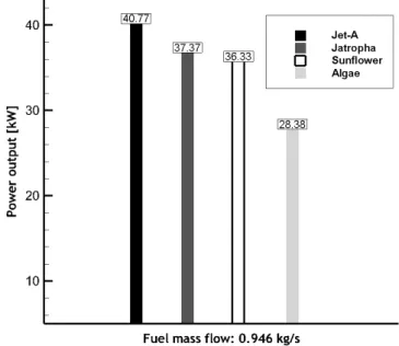
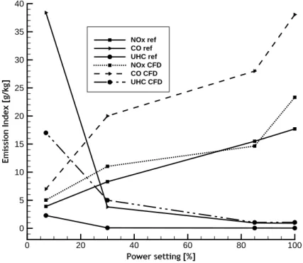
5.3 Energy extracted from the combustion of Jet-A vs the biofuels, at a constant ˙mf. 72 5.4 Results validation: ICAO's measures vs CFD calculations while burning Jet-A. . . . 73
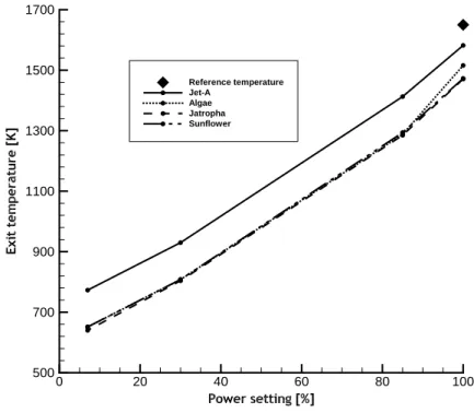
5.5 Combustor exit temperature throughout ICAO's LTO cycle, while burning Jet-A and the biofuels. . . 74
5.6 Contours of the combustor exit temperature (K), while burning jatropha biofuel, at full power. . . 75
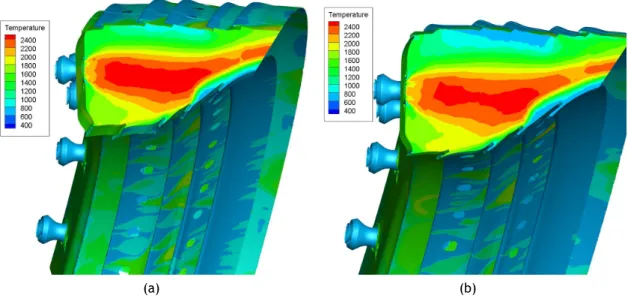
5.7 Contours of the cross section temperature (K), while burning: (a) jatropha biofuel, at a 100% power setting and (b) algae biofuel, at a 85% power setting. . . . 76
5.8 Contours of the cross section temperature (K), while burning: (a) sunflower bio-fuel, at a 30% power setting and (b) jatropha biobio-fuel, at a 7% power setting. . . 77
5.9 (a) Cross section contours of N Ox concentration [kg/kg], while burning algae biofuel at 85% power, and (b) EI results of N Ox, resultant from the combustion of Jet-A and the biofuels, throughout ICAO's LTO cycle. . . 78
5.10 Contours of N Ox concentration [kg/kg], while burning jatropha biofuel at full power. . . 79
5.11 Contours of CO concentration [kg/kg] at 85% power, while burning: (a) jatropha
biofuel, and (b) algae biofuel. . . . 80
5.12 EI results of (a) CO and (b) U HC, resultant from the combustion of Jet-A and the biofuels, throughout ICAO's LTO cycle. . . 80
5.13 Contours of CO2 concentration [kg/kg] at 100% power, while burning: (a) sun-flower biofuel, and (b) jatropha biofuel. . . . 82
5.14 EI results of CO2, resultant from the combustion of Jet-A and the biofuels, through-out ICAO's LTO cycle. . . 82
A.1 ICAO reference LTO-cycle. . . 93
B.1 CFM56-3 combustor photograph. Here it can be seen the tape/markers added to aid the scanning process. . . 95
B.2 3D model combustor, obtained from the post-processing step in Artec Studio 9.2. 95 B.3 Measurement methodology that can be used in Artec Studio 9.2. . . 96
B.4 Close up on the tip of the scanned fuel injector. . . 96
B.5 Activation of a selected section of the STL 3D model . . . 96
B.6 Views of the CAD combustor model section used in the simulations. . . 97
B.7 Close up on the primary and secondary swirlers, along with the placement of the fuel injector. . . 97
C.1 Mesh of the model combustor before the upper volume of the dome being removed. 99 C.2 Mesh of the model combustor after the upper volume of the dome being removed. 99 C.3 Close up of the layers creation, with a sectional cut of the model, using Paraview. 100 D.1 Converged solution for second order method. . . 102
D.2 Temperature contours, with the introduction of a cone angle of 60o. . . 104
D.3 Contours of static temperature [K], while burning jet-A at full power through: (a) a quarter section view, and (b) a cross section of the combustor. . . 104
D.4 Additional combustor contours: (a) turbulent kinetic energy and (b) mean mixture fraction . . . 104
List of Tables
2.1 PLF in CC's . . . 37
2.2 LTO cycle measurements for the CFM56-3 . . . 48
4.1 Mesh generation inputs and results using HELYX-OS . . . . 62
4.2 Air mass flow (kg/s) inputs, for each boundary at its respective power setting, while burning Jet-A . . . 67
A.1 ICAO gaseous emissions standards . . . 93
A.2 Pollutant effects and their limitation strategy . . . 94
C.1 Combustor model boundary names/type . . . 100
D.1 Fuel stoichiometric ratios obtained with CEA; flash point and LHV for the fuels in study . . . 101
D.2 Jatropha, Algae and Sunflower, biofuel fatty acid composition . . . 101
D.3 Oxidizer and temperature species model inputs values . . . 101
D.4 Relevant data for the CFM56-3, obtained from Pedro's work . . . 102
D.5 Solution control parameters for flow Courant number, ERF and URF . . . 102
D.6 Air mass flow (kg/s) inputs, for each boundary at its respective power setting, while burning the biofuels . . . 103
List of Acronyms
AFR Air to Fuel Ratio App. Appendix
ASTM American Society of Testing and Materials Bio-SPK Bio-derived Synthetic Paraffinic Kerosene BTU British Thermo Unit
CAD Computer-Aided Design
CC Gas turbine Combustion Chamber CEA Chemical Equilibrium with Application CFD Computational Fluid Dynamics
CPU Central Processing Unit CZ Combustion Zone DLE Dry Low Emissions DLN Dry Low N ox
DLR Deutch Zentrum fur Luft-und Raumfahrt DNS Direct Numerical Simulation
EI Emission Index
ERF Explicit Relaxation Factor EU European Union
EV Environmental Burner EVM Eddy Viscosity Model FAME Fatty Acid Methyl Ester FAR Fuel to Air Ratio FGB First Generation Biofuel
FSRFL Fuel Stream Rich Flammability Limit FT Fischer-Tropsch
GE General Electric GHG Green House Gas GTC Gas Turbine Combustor GTE Gas Turbine Engine
H Hydrogen
HCN Hydrogen Cyanide
HEFA Hydroprocessed Esters and Fatty Acids HHV Higher Heating Value
HPC High Pressure Compressor HPT High Pressure Turbine
ICAO International Civil Aviation Organization ICE Internal Combustion Engine
IPCC International Panel on Climate Change KPPSMOKE Kinetic Post-Processor
LES Large Eddy Simulation LHV Lower Heating Value LPC Low Pressure Compressor LPP Lean Premixed-Pre vaporized
LPT Low Pressure Turbine LTO Landing and Take-Off MAC Modern Annular Combustor
NASA National Research Council of Canada NCN Cyanonaphthalene
NRC National Research council of Canada P&W Pratt and Whittney
PDF Probability Density Function PLF Pressure Loss Factor
PM Particulate Matter PN Particulate Number PPM Part Per Million
PRESTO! PREssure STaggering Option PZ Primary Zone
RAM Random Access Memory
RANS Reynolds-Averaged Navier-Stokes RQL Rich-Quench-Lean
RSM Reynolds Stress Model SAC Single Annular Combustor SEV Sequential Environmental Burner SFC Specific Fuel Consumption SGB Second Generation Biofuel
SIMPLE Semi-Implicit Method for Pressure Linked Equations SME Soy-Methyl-Ester
SN Smoke Number
SPK Synthetic Paraffinic Kerosene STL Stereo Lithography
TAP Transportes Aéreos de Portugal TAPS Twin Annular Premixing Swirler TTQ Temperature Traverse Quality UBI Universidade da Beira Interior UHC Unburned Hydrocarbons
UNFCCC United Nations Framework Convention on Climate Change URF Under Relaxation Factor
USA United States of America WLE Wet Lean Emissions WWII World War Two
Nomenclature
1 2v
2 Mass specific system kinetic energy [J /kg]
A Area [m2]
C Heat capacity [J /K]
Cµ k- ε model constant [0.09]
cp Specific heat at constant pressure [J /kg.K]
CO2 Carbon dioxide [−]
CO Carbon monoxide [−]
Dsw Swirler diameter [mm]
F Engine thrust [kN ]
F00 Engine take-off thrust [kN ]
Gm Axial flux of angular momentum [−]
Gt Axial thrust [−]
gz Mass-specific system potential energy [J ]
H/C Hydrogen to carbon ratio [−]
m Mass [kg]
˙
m Mass flow rate [kg/s]
M Molecular weight [kg/kmol]
n Number of moles in a gas [kmol]
nf uel Moles of fuel combusted [kmol]
nwater Moles of water vaporized [kmol]
N2 Diatomic nitrogen [−]
N Ox Oxides of nitrogen [−]
O2 Oxygen [−]
p Pressure [P a]
pf und Fundamental pressure [P a]
Q Heat transfer [W /m2]
qcv Heat transferred across the control surface
from the surroundings to the control volume
[W /m2]
RCO Carbon monoxide oxidation rate [mol m−3s−1]
rp Pressure ratio p2/p1 [−]
Rµ Universal gas constant [8315 J /kmol.K]
SN Swirl number [−]
SGgas Specific gravity of gas with respect to air [M W gas/28.96]
SN Smoke number [−]
SOx Oxides of sulphur [−]
T Temperature [K]
t Time [s]
Tad Adiabatic flame temperature [K]
T SF C Trust Specific Fuel Consumption [g/kN ]
U Compressor outlet velocity [m/s]
v Velocity [m/s]
V Volume [m3]
Wcv Work done by the control volume [J ]
u velocity [m/s]
nl Number of layers [−]
Greek letters
γ Mass fraction [kg/kg]
δf Final layer thickness [−]
δs Layer stretching [−]
ε Eddy viscosity [m2/s]
ηjoule Efficiency of the air-standard Brayton - Joule
cycle
[−]
µ Absolute viscosity [P a.s]
µT Turbulent viscosity [P a.s]
π00 Engine pressure ratio at take-off [−]
ρ Density [kg/m3]
σ Stress tensor [P a]
τ Sheer stress [P a]
ϕ Equivalence ratio [−]
Scalar such as pressure, energy or species concentration
[−]
χ Mole fraction [−]
Subscripts
0 Engine inlet stage 1 Compressor inlet stage
2 Combustion chamber inlet stage 3 HPT inlet stage
4 LPT outlet stage 5 Engine exit stage
a Air
c Combustion chamber f fuel
i Element/Molecule Inlet
ref Reference state Reference data o Outlet
Chapter 1
Introduction
1.1
Motivation
In a world which the constant concern of global warming is an every day matter, the emissions that result from the combustion of fossil fuels are usually placed at the top as the main re-sponsible for Greenhouse Gas (GHG)1emissions, which are appointed as the primary factor that
leads to global warming. The aviation industry by itself is responsible for around 3% of the total European Union (EU) GHG emissions, but the problem is that aviation is the only direct source of emissions into the upper atmosphere and that these numbers are increasing fast, 87% since 1990 [1]. This increase is mainly because people are seeking more and more aviation as a transport due to their increasingly lower costs throughout the years, and its environmental costs being neglected. Just to clarify the magnitude of these environmental costs, a person flying from London to New York and back, generates roughly the same amount of emissions as an average person in the EU does by heating their home for a whole year [2]. By 2020, global aviation emis-sions are projected to be around 70% higher than in 2005, even if fuel efficiency improves by 2% a year. Yet, darker forecasts are made by the International Civil Aviation Organization (ICAO), which predicts that by 2050 these emissions could grow up to 300%-700% [3]. This increase in emissions drifts of course by the continuous increase of the demand of fuel, which in turn comes from the increase in the number of operational aircraft. In contrast, the resource of fossil fuel is depleting and will be finished in a near future. In fact, according to British Petroleum (BP) [4], known oil deposits will only last until 2068, if we carry on this consumption rate. Consequently, the price of jet fuel has been increased rapidly from $0.72/gallon (2002) to $2.98/gallon (2013) in 10 years [5]. Fossil fuel subsidies, which amounted to half a trillion US Dollars worldwide in 2011 [6], are effectively an incentive to pollute and as such are a major blocker to sustainable energy development.
Fortunately, we have the technology and practical solutions at hand to reduce the amount of heat-trapping emissions resultant by the continuous increase in traffic in the aviation industry. These solutions come in the form of protocols, improvements in aircraft structures/engines and alternative fuels. An example of a protocol that commits to reducing GHG emissions is the Kyoto Protocol. This protocol established that between 2008 and 2012, developed countries and countries in economic transition would have to reduce their GHG emissions by about 5% below their 1990 levels [7]. Overall, this protocol was a success. The 37 industrial nations that stuck with the protocol, after the United States of America (USA) pulled out in 2005, say they exceeded their promises, cutting their emissions during the agreed timeframe to an average of 16% below 1990 levels [8]. However, these major cuts came from non-rich industrialized countries witch where not the focus of this protocol and whose economy had collapsed after the fall of the Berlin wall, meaning that reductions would have happened anyway. In the meantime, emissions in the
1
A GHG is a gas in an atmosphere that absorbs and emits radiation within the thermal infra-red range. This process is the fundamental cause of the greenhouse effect (global warming).
Chapter 1 • Introduction Motivation
rest of the world have increased sharply thanks to rapid industrialization nations like China, which are not covered by the original deal.
Changes in the structure of aircraft have also been held in order to decrease fuel consumption, thus reducing the emissions of GHG. An example of this is the new design feature in the wing tips, blended winglets. In this design the wingtip sweeps upwards reducing drag witch consequently increases fuel efficiency. Modifications in the engines have also taken part in the quest to reduce GHG emission from civil aviation. The most significant change in the engine configuration was an increase in its bypass ratio2. This increased greatly the fuel efficiency in civil aviation when
compared to its predecessor low-bypass engine, that was more compact but less fuel efficient and much more noisier [9]. The CFM56 engine is a successful example in the family of high-bypass engines.
Although changes like these did reduce the GHG emissions, they still present some problems. Modifications in aircraft components require a huge amount of money to take place; this is because these specific changed features has to be implemented in every single plane of the fleet, in order to achieve the desired reduction in GHG emissions. Another problem is the dependence in fossil fuels; these changes still do not resolve the fact that kerosene3 will no
longer be available in the near future, due to the disappearance of known oil deposits. So changing the fuel source is one of the few options that remain for the aviation industry to reduce its GHG emissions. Alternatives like solar, electric and hydrogen propelled aircraft are currently being researched, but are not expected to be implemented in the near future due to the aviation need for high power-to-weight ratio4 and globally compatible infrastructure.
The seek of a renewable drop-in fuel5suitable for the aviation industry, comes as the best solu-tion to resolve all the problems mensolu-tioned above. The environmental effects of any alternative fuel must be considered, this includes emissions from the engine and also life-cycle effects as-sociated with the production and use of an alternative fuel [10]. Safe and reliable operations of the engine must not be compromised in any way. Biofuel6 is a suitable choice which not
only could significantly lower GHG emissions but it is also a renewable fuel. Since 2008, several flight tests have been performed to investigate the technology and safety, using biofuel [11]. The problem is that the major part of these tests were performed using blends of biofuel added to conventional jet fuel that, which consequently, did not remove the fossil fuel component. However, in 2012, the National Research Council of Canada (NRC) performed the first flight on a civil aircraft, using a 100% unblended biofuel obtained from the plant Brassica Carinata. Overall, this flight test was a success. Tests results show that this biofuel reduced emissions and provided a better fuel efficiency than petroleum aviation fuel [12].
Biomass derived from organisms, like switchgrass and waste, are the source of which future biofuels should be produced from. This is because, unlike biofuel produced after food crops,
2
The bypass ratio defines the amount of air that bypasses the core of the engine, from the air that goes through the core. For a deeper insight in the bypass ratio concept, it is advised to check section 2.1.2.
3Kerosene is a combustible hydrocarbon liquid widely used to power jet engines of aircraft. 4
Power-to-weight ratio is a measurement of actual performance of any engine or power source. 5A drop-in fuel is an alternative fuel that does not require adaptation of the fuel distribution network nor the engine fuel systems. It can be used without restrictions on aircraft or engine operability.
6
Biofuels are energy sources made from living things, or the waste that living things produce, also known as biomass.
Motivation Chapter 1 • Introduction
like soy been, biomass derived from non-food crops do not enter in conflict with food resources. If the production of biofuel did enter in conflict with food resources, then there would be a big problem to deal with in the future. This is due to the inevitable increase in the price of food, putting biofuels as a global responsible for the crises that would appear. Even still, some do present problems with the use of biomass to obtain biofuel. Biomass production under intensive monoculture systems can have negative impacts on biodiversity, including habitat loss, the expansion of evasive species, contamination from fertilizers/herbicides and air pollution resultant from the production process of biofuel [13]. The continuous demand of biofuel in the future would also inevitably result in a continuous increase of its price, similar to the price increase that is taking place with fossil fuel. To solve some of these problems, the author suggests that if each airliner could build their own environmental controlled infrastructures to produce their own biofuel, in areas which are less conducive to farming, e.g. cities, it would give airliners a steady supply of fuel which could reduce significantly the pricing factors and could mitigate the problem with habitat loss. This solution might not supply 100% of the fuel demands, but it certainly would be of benefit.
The main impact of trends and developments with the use of biofuels relative to combustor7
design, will be felt in fuel-nozzle design for multifuel capability, and in fuel/air management for minimum soot8 and gaseous emissions. These emissions include Oxides of Nitrogen (N O
x),
Unburned Hydrocarbons (U HC), Carbon Monoxide (CO), Particulate Matter (P M ) and Oxides of Sulphur (SOx)9. Although these pollutants do not contribute directly to global warming,
they are hazardous to human health and therefore must be reduced. Carbon dioxide (CO2) and
water vapour (H2O) are also products of the combustion process, but they are not regarded as
pollutants because they are a natural consequence of the complete combustion of a hydrocarbon fuel. However, these two contribute to global warming and the only way to reduce them, is to burn less fuel [14].
The problem of controlling emissions is complicated because of the fact that Gas Turbine Engines (GTE) operate over a wide range of power and ambient conditions. Aircraft engines have two requirements; the first is for very high combustion efficiency at low power, this is due to the large amount of fuel burned during taxiing and ground manoeuvring, and the primary problem here is the reduction of U HC. At take-off power, climb and cruise the main concern are N Ox.
ICAO sets standards on a worldwide basis, for both Landing and Take-off (LTO) cycles, and also for cruise at high altitude; the first is concerned with air quality in the regions surrounding airports, and the second with ozone depletion in the upper atmosphere [15].
Research and development of biofuel for the aviation industry promises a prospect and interest-ing work, however it also issues many challenges due to strict requirements of aviation fuel that are regulated by the American Society for Testing and Materials (ASTM). As these requirements are achieved, so as combustion products and the efficiency of these biofuels been correctly studied, the world takes a step closer to become less dependent of fossil fuels and mitigate global warming issues. This moment will come sooner than people think, and as the Saudi oil Minister Sheik Ahmed Zaki Yamani said in the 1970's, "The Stone Age did not end for lack of stone, and the oil age will end long before the world runs out of oil." [16].
7The combustor is the component of the gas turbine engine, in which combustion takes place. 8The term soot refers to impure carbon particles that result from the incomplete combustion of hydro-carbons.
9
Chapter 1 • Introduction Main Goals
1.2
Main Goals
The present work firstly focuses on the construction of an annular combustor of the CFM56-3 engine. A 3D scan was performed on a real sized combustor in order to extract all the mea-surements needed to conduct a Computer Assisted Design (CAD) with the commercial software
CATIA V5. This geometry is then imported into a CFD software, ANSYS Fluent, to perform a
numerical analyses in order to study the combustion of some biofuels, when injected into the combustor. The parameters analysed were the quantity of emitted pollutant, namely N Ox, CO
and U HC, and the energy extracted from the combustion of these biofuels, throughout ICAO's LTO cycle. The aim is to verify if this biofuel could substitute completely conventional jet fuel, in a combustion point of view.
The selection criteria, adopted by the author, to choose which biofuels should be used in this study, where based on their sustainability characteristics and life-cycle assessment. The impor-tance of these features are discussed in chapter 3. The biofuels sources chosen were extracted from algae, sunflower and jatropha seeds.
The final goal for this study, is to present a detailed guide for the CFD problem setup, in a way that any student or engineer could successfully perform a non-premixed combustion case, with
ANSYS Fluent.
1.3
Task Overview
In the current chapter, the author expresses his motivation behind the development of this thesis. Here, the problems are presented, as well as the solutions that appeared to resolve these problems; why did these solutions not work, and what is the best solution to resolve the presented problems, following with the challenges associated with it. The objectives proposed for this thesis are also presented, focusing which parameters will be studied when a biofuel is used as the main fuel, in a GTE. An Historical review is presented in order to understand the problems and concerns that appeared throughout the time of combustors development. Finally, a bibliographic review is presented, focusing on other works related to the subject and pointing out their importance in this area.
This chapter was written with the intent that any person with minimal scientific knowledge could understand what is proposed for this work.
Chapter 2 introduces the principals behind a GTE. A close-up on the main requirements, types and configurations of the combustor are then presented along with some combustion fundamen-tals.
Chapter 3, the properties, composition and specifications of conventional jet fuel are analysed and then compared to the chosen biofuels.The reasons that led to the selection of these bio-fuels, are also mentioned in this chapter. The economical, sociological and ecological effects associated with the use of biofuels are analysed.
Chapter 4 starts by introducing the theory behind numerical modelling. The model construction, which includes the scanning process, the CAD design and the generation of the numerical mesh, is then explained in detail along with the problem set-up.
Historical Review Chapter 1 • Introduction
Chapter 5 presents the numerical results obtained from the CFD simulation. The results are then explained in detail and discussed throughout this chapter. Possible problems encountered in this work are also mentioned. To conclude this chapter, the conclusions resultant from the CFD simulation are presented along with future work proposals.
1.4
Historical Review
For the last two centuries, investigators made many attempts in order to find the best mobile capable of transforming the fuel energy into mechanical work, in a most simple way. Since then, the evolution of the GTE is directly related to the evolution process of the combustor, due to the importance of this in a GTE.
Sir Isaac Newton was the first to theorize, in the 18th century, that a rearward-channelled explosion would propel an aircraft forward at a great rate of speed, in other words, as the hot air blasts backwards through the nozzle, the plane moves forward. This theory was based on his third law of motion; for every action, there is an equal and opposite reaction. Since then, several attempts have been made in order to build a engine that would work on this principle. The first attempt was made by Henry Giffard in 1852, who developed a three-horse power steam engine to propel his airship. Although this flight was counted as a success, the airship lacked the power to navigate properly [17]. In 1894, Hiram Maxim also did not succeed to propel his triple biplane with a steam engine, in fact it only flew for a few seconds [18]. These flights failed due to the fact that these steam engines were powered by heated coal, making them too heavy for flight. The internal combustion reciprocating engine10then appeared along with the first flight of the Wright Bothers, in 1903, becoming the sole means to propel aircraft until late 1930s.
World War II contribution to jet engine development.
Military aircraft were propelled by an internal combustion piston engine, by the time the ap-pearance of World War II (WWII) was imminent. The ability for these aircraft to accelerate during flight, in order to operate in combat situations, was limited to the size of its engine, the amount of energy in the fuel, and how quickly could the fuel be burned in the engine. Some of these problems became to complex to resolve, for example, one way to obtain more power from a piston engine is to increase the size of the engine, but as this is done, the engine will become heavier which will affect the aircraft agility, thus it is not desired in the military field. Problems regarding propulsive efficiency were also encountered; this declined as blade tips approached the speed of sound. All these problems motivated engineers to seek a new type of power plant, which would later be known as a gas turbine engine, commonly known as jet engine.
A British pilot named Frank Whittle, designed and patented the first turbo jet engine in 1930, but it was in Germany, by the hands of a physicist named Hans Von Ohain, that the first jet engine first flew in 1939 [19]. Whittle did not succeed in making the first turbo jet flight, because there were many problems regarding the combustor systems. The method adopted by Whittle to prepare the fuel for the combustion process, was to heat it above the boiling
10
Also known as piston engine; is a heat engine that uses one or more reciprocating pistons to convert pressure into a rotating motion.
Chapter 1 • Introduction Historical Review
point of its heaviest hydrocarbon ingredient, in order to vaporize the fuel completely before the combustion process. The fuel was maintained at high pressures so that vaporization would not occur until it was injected into the combustor, through a nozzle that then reduced the fuel pressure to that of the combustion zone. With this design, Whittle encountered some difficulties relative to its vaporizing tubes, which were experiencing thermal cracking and coking up issues. Difficulties were also encountered in controlling the fuel flow rate. [14]
After many attempts on making a functional combustor, Whittle replaced the vaporizer tubes with a pressure-swirl atomizer and placed a large air swirler located at the upstream end of the liner, as shown in figure 1.1. The function of this last feature was to create a reversal toroidal flow, to recirculate a portion of the hot combustion products, providing a rapid mixing of fuel vapor, air and combustion products that was required to achieve high heat-release rates. Stub pipes were also implemented in order to supply the required amount of air, to complete the combustion process and to reduce the gas temperatures to an acceptable level for the turbine. This combustor was then implemented in the Power Jets W1 engine, which employed 10 separate tubular combustors in a reverse-flow arrangement, to permit a short shaft engine. This engine was used by Whittle to propel the first British turbojet-powered flight, in the evening of May 15, 1941 [14].
Figure 1.1: Reverse-flow atomizer combustor [14].
Later on, and still in Britain, the straight-through combustor was invented and implemented in the De Havilland Goblin engine, as well as the first annular combustor, which was employed on the Metrovick engine. The invention of this annular combustor came with the use of upstream fuel injectors, and the introduction of downstream dilution air; the upstream fuel injectors were claimed to have the fuel droplets at a higher residence time in the combustion zone, providing more time for fuel evaporation. The downstream dilution air served two purposes; firstly, air is introduced through a first row of scoops, supplying the needs of air to complete the combustion process, with the remaining of this air serving for dilution purposes; the second row of scopes was solely for dilution purposes. Low Pressure losses and low pattern factors11where achieved, but
11
The pattern factor represents the outlet temperature of the combustor, and it should be at a uniform temperature at any given point within the outlet of the combustor.
Historical Review Chapter 1 • Introduction
the fact that this configuration made the engine too heavy, and that the scoops were subject to burnout because of their exposure to the high-velocity combustion gases, made them non feasible for aircraft applications. Upstream fuel injectors are also no longer used, because it is very difficult to eliminate entirely the problem of carbon deposition on the atomizer face. The Jumo 004 and its contemporary BMW 003, where the only axial-flow12turbojet engines to go into production during WWII [20]. The Jumo 004 was developed by Anselm Franz, and employed six-can combustors. Franz was the first to recognize the superiority of an annular combustor design, but he opted for the can configuration because it would present less of a problem, and allow bench testing with a single can [21]. Three of these cans carried spark plugs, using interconnectors13to guarantee ignition in the remaining combustors. Each of these combustors were designed to burn diesel fuel, with fuel pressures of up to 5.2 MPa [14] from a pressure swirl atomizer. The approach held in the combustor design was to derive a flame chamber region in the combustor for primary combustion at close to stoichiometric ratio [21]. In order to obtain good mixture and a short flame length, the primary combustion air was introduced in the combustion chamber through helical slots to produce a swirl; the fuel was sprayed upstream into the primary combustion zone. A cutaway view of the combustor can is shown in figure 1.2.
Figure 1.2: Jumo 004 tubular combustor [21].
The BMW 003 was the world's second successful axial-flow turbojet engine and the only one that was used during WWII. Although the development of this engine began before the Jumo 004, the BMW 003 went into production later due to development problems. This engine employed an annular combustor, which had 16 equispaced, downstream-spraying pressure atomizers. The fuel nozzles were surrounded by a baffle14and the primary combustion air flowed both through and around the nozzle. The required dilution air to complete combustion and lower the temper-ature of the combustion products, was obtained through 40 scoops attached to the outer liner.
12
An axial-flow turbojet allows air to flow straight through the engine, thereby creating less resistance than the centrifugal-flow engines turbojet designs, by Hans von Ohain and Whittle.
13Interconnectors, also known as cross fire tubes; provide the mean to initiate combustion in the com-bustors, without spark plugs.
14
A baffle consists usually of a plate, placed in the flow stream to create a region of low velocity and flow reversal, in order to improve flame stabilization.
Chapter 1 • Introduction Historical Review
This configuration resulted in a combustor which had a relatively low pressure loss, but also a high length/hight ratio, which led to a long engine. Initially, the average life span of these combustors were very low, about 25 hours [20]. This was due to the fact that these combustors were made from a mild sheet steel with an aluminium coating, which had a heat resistance below of the required value.
The slow development of the jet engine during WWII, was due to the confidentiality of inventions and developments that nations had during the war. The only nation to successfully introduce a combat jet plane during WWII, was Germany with the Messerschmitt Me-262, but they were introduced to late to be decisive.
The end of WWII and the technological explosion of jet engines
The surrender of Germany, in 1945, exposed inventions hidden during wartime, which made possible to solve some of the problems that Britain and Germany had with their jet engines. The engines pre WWII, were fuel inefficient, extremely pollutant, unreliable and noisy. With the junction of both technologies, these engines matured, and in less then 20 years they became the standard means of propulsion for civil aircraft [15].
General electric (GE), Rolls-Royce (RR) and Pratt & Whittney (P&W), were among the first to start developing an efficient jet engine for aircraft application, and lost no time in producing their own combustor designs. GE employed a reverse flow combustor on the J31 engine, which was whittle-derived; a straight-through version was then implemented on the J33, J35 and J47 [14]. P&W also held with the tubular combustor in the J57 jet engine, in the early 1950s. The J57 employed eight of these liners within an annular casing. Each of these combustors had a perforated tube, which went through its axial axis, and extended of up to a half the length of the combustor. As a consequence, this central tube made the tubular combustor act like an annular combustor, being supplied with fuel from six equispaced, pressure-swirl atomizers. [14]
Figure 1.3: On the left of this figure, it is represented an axial cross-sectional view of a double annular combustor, and on the right, a front view of the injectors are displayed [22].
In the mid 1970s, the preoccupation of pollutant emissions resultant from aircraft operation led engineers to search for technological improvements on engine designs to reduce emissions and make the engine more fuel efficient. The quest to achieve low emission combustors has
Historical Review Chapter 1 • Introduction
led combustion engineers to develop staged combustion techniques, wherein a set of burners is used for low speed and low temperature conditions such as idle, and additional burners are used for high temperature operating conditions, such as take-off conditions. One particular concept of this staged combustor is the Double Annular Combustor (DAC), illustrated in figure 1.3, wherein the two stages are located concentrically in a single combustor liner. The pilot stage is normally located concentrically and outside, and is used for idle conditions, i.e, low fuel/air ratios and low temperatures, to achieve good ignition and low CO and HC emissions. The main stage section is located concentrically inside, and is used for high temperatures and relatively high fuel/air ratios, e.g, take-off conditions. This main stage was designed to provide a lean15 flame with minimal time for NO
x formation. The DAC appeared in the 1950s, with
the J34 engine, but this concept was ahead of its time, so there was a lack of interest on this combustor, until GE came and adopted it in their CFM56-5B engine, in the mid 1990s [23]. Another effort in reducing emissions resultant from the combustion process, was the invention of the Twin Annular Premixing Swirler (TAPS) combustor, in 1995, as a emissions reduction program between GE and the National Aeronautics and Space Administration (NASA) [24]. The TAPS was developed through the lessons learned with fuel staging of the DAC and from the experience gained with Dry Low Emissions (DLE) lean-premixing combustors in aero-derivative gas turbines16. The TAPS combustor concept is a lean burn system, in which each fuel injector contains a centre pilot and a concentric outer main, as shown in figure 1.4. The central pilot burns in a similar manner to traditional combustors. The fuel is 100% in the pilot, when the engine is starting and when operating at low power. At high power, the fuel is injected through the main, which is a large effective area to burn fuel lean. The aim is then to reduce pollutant emissions, resultant from the Landing and Take Off cycles (LTO), which are defined by ICAO.
Figure 1.4: TAPS Fuel Injection Concept [24].
15Lean mixture refers to a low fuel to air ratio, i.e, there is excess air in the combustion process. 16
The concept of DLE and lean-premixing combustors, regarding industrial gas turbines, is later explained in this historical review.
Chapter 1 • Introduction Historical Review
Industrial Gas Turbines and their quest to achieve Dry Low Emissions (DLE)
When Industrial Gas Turbines appeared from aero-derivative engines for power generation pur-poses, they did not have the same impact that aero engines had with the aviation industry. These industrial gas turbines were not competitive at the time due to the fact that they pro-duced low power and low thermal efficiency. However these were improved, and by the end of the 20th century, gas turbines were capable of outputs of up to 300 MW and thermal efficiencies of up to 40%, which made them, along with steam turbines, the major source of power genera-tion [15]. When gas turbines made an entry in markets such as pipelines, electricity generagenera-tion and mechanical drives, they were immediately subjected to emission regulations, such as aero gas turbines were subjected when they were implemented in civil aircraft. These restrictions were mostly concerned with the reduction of N Ox, CO2 and U HC. The main manufactures
of large industrial gas turbines; Alstom, GE, Siemens and Mitsubishi, started then to develop low-N Oxcombustion systems, which were the key for competitive gas turbines.
The easiest way of controlling unwanted emissions to the atmosphere, was to prevent their pro-duction in the first place through changes in the combustion design, which led to the use of DLE or Dry Low N Ox(DLN). DLE combustion systems address the production of N Oxat source with
a design that does not rely on injected diluents, hence the term "dry"17. Promising technologies like Lean-Premixed Pre-vaporized (LPP) combustion, staged combustion, catalytic combustion and rich-burn lean quench combustion, all had the aim to reduce N Oxformation, by the
reduc-tion of the combusreduc-tion peak temperature. The lean premixed system, however, was and still is the combustion system of choice with millions of operating hours recorded [25]. As explained before in this work, the term "lean" refers to the combustion of fuel with excess air, which lowers the temperature of the reaction, thus reducing N Oxformation. The main features that
a lean pre-mix combustor design comprises are a Fuel/air injection device, stability device, pre-mixing zone and a flame stabilization zone. The differences in the exit temperature of a diffusion combustor, e.g. Single Annular Combustor (SAC), and a lean premixed combustor are demonstrated in the CFD calculation in figure 1.5. As we can verify, conventional diffusion flame combustors have a very high temperature primary zone due to the high turbulence; premixing and leaning out the mixture, as is the case of the DLE combustor, achieves the desired effect of a more uniform and lower peak combustor temperature, thus resulting in low thermal N Ox
formation [25].
Figure 1.5: CFD calculation temperature distribution in a diffusion flame combustor (a) and in a DLE lean premixed combustor (b) [25].
The lean premixed combustor system has not yet been implemented in aero GTE, because it has
17
Initially N Oxreduction resulted from the injection of water into the primary zone, Wet Lean Emissions
(WLE), but WLE technology demanded cleaning large amounts of water, it was heavy and was difficult to install offshore.
Historical Review Chapter 1 • Introduction
some disadvantages that do not influence that much an Industrial GTE; generally speaking, DLE technology is not yet fully matured when compared to SAC, leading to reduced reliability, but the main disadvantages of running in lean conditions are the marginal blow-out limit and risk of high CO/U HC emissions at low combustion temperatures, due to the incomplete combustion. This possibility cannot even be considered in aero GTE, because if a blow-out does occur a possible disaster may take place. Also lean premixing combustors do not have the emission advantages at low power conditions, such as idle, at which aircraft spend a considerable time in this power setting, which means that at operating loads below 60%, there is a big increase in
N Oxand CO emissions [26].
Important developments in order to achieve low emissions were also held by Alstom. With the introduction of the two similar GTE, the GT24 and the GT26 came the sequential combustor, adding the reheating principle to GTE, which offered superior operating flexibility, low emis-sions and high part-load efficiency. This combustion system is based on the environmental (EV) burner combustion concept, followed by the Sequential Environmental (SEV) burner in the sec-ond combustion stage, both held in an annular combustor. The concept is presented in figure 1.6. The compressed air is firstly heated in a first combustor, the EV combustor, with the addi-tion of about 50% of the total fuel. Combusaddi-tion gases then expand through the High- Pressure (HP) turbine, lowering the pressure by approximately a factor of 2. The remaining fuel is then added with some cooling air in the second combustion chamber, the SEV combustor, where the combustion gases are reheated in order to maximize the turbine inlet temperature and finally expand in the four-stage Low-Pressure Turbine (LPT) [27]. Lower emissions are achieved through this concept, because a reheat combustor makes a more efficient use of the oxygen by burning twice in the lean premix mode, and because there is a increased flexibility due to the flame stabilization by autoignition, which allows the GTE to operate in a wide range load, with low
N Oxemissions.
Figure 1.6: Alstom's GT24/GT26 sequential combustion system [28].
Although there was some modifications in the combustor systems throughout its development, the basic design features of aero-engines combustors have remained largely unchanged, meaning that combustor technology has developed gradually and continuously, rather than through a dramatic change, which is why most of the aero-engine combustors now in service tend to resemble each other in size, shape, and general appearance. The main components of the combustor are then a diffuser, a combustion chamber, the fuel injectors, the casings and in
Chapter 1 • Introduction Bibliographic Review
the case of can combustors, Interconnectors. Within the liner itself, the distribution of air is arranged to ensure that the primary combustion zone operates in a much higher fuel/air ratio then the rest of the combustor zones. Extra air is admitted downstream the combustor, and it has two functions; the extra air admitted in the primary zone is to complete the combustion process; the air injected more downstream serves as wall cooling purposes and to dilute the combustion products to a temperature acceptable for the turbine. These components and their fundamentals will be explained with more detail in section 2.2.
1.5
Bibliographic Review
With the invention of the GTE came the need to develop models to simulate the entire engine and each of its components, in which the combustion section was among those that most inter-est was held. However, it took quite a long time to develop such models, due to limitations in the existing computational hardware, thus in the first years of GTE development, practical stud-ies were dominant. As computers became more powerful, better analytical/numerical models were developed, especially Computational Fluid Dynamics (CFD) modelling, which is now widely applied as a combustion optimization tool. Combustion engineers are now able to model react-ing multi-phase flows in a realistic geometry with good mesh resolution, thus increasreact-ing greatly CFD applications in industries, which enhances the rapid growth and sophistication of these. In the following studies presented, focus was made on those that had the aim to analyse the emissions and the energy extracted, resultant from the combustion of biofuels in GTE's. Each of the following reviews present different and important aspects to consider in this thesis. Both experimental and computational studies will be presented, in order to verify if these achieve similar results, making it possible to conclude if biofuels are or not a viable option for the future of aviation fuel.
Regarding biofuels, a very detailed review of typical biofuels for aviation alternative fuel pur-poses was performed by Reksowadojo et al. [29]. Here he presented several studies performed with various types of biofuels, namely Fatty Acid Methyl Ester (FAME), Bio-derived Synthetic Paraffinic Kerosene (Bio-SPK) and Fischer-Tropsch Synthetic Paraffinic Kerosene (FT-SPK). He then concluded his review by analysing real flight test demonstrations using the previous biofu-els. The result of this work is a very good understanding of what has been done in the research of biofuels for aviation alternative fuel purposes.
Experimental Studies/Methods
Lobo et al. [30] performed the first tests of PM emissions in a commercial jet engine, a CFM56-7B, when burning conventional Jet-A1 fuel, Biomass (FAME) and FT fuels. The exhaust samples were obtained from the exhaust of the engine, which was mounted in an open air test cell, and these were extracted using a PM probe and rake assembly coupled to a sample train. The PM size and distributions and its associated combustion CO2 concentrations, were measured by
a particulate spectrometer, the Cambustion DMS500. The ICAO LTO Cycle18 was adopted for
the engine power settings along with a 3% and 65% power setting, which are not included in
18
ICAO LTO Cycle is defined by the following power settings: 7%, 30%, 85% and 100% and these correspond to idle/taxi, approach, climb-out and take-off, respectively.
Bibliographic Review Chapter 1 • Introduction
ICAO LTO cycle. In order to accomplish a comparison between fuels at the same engine power settings, the measured fuel flows at each power condition were adjusted to account for the different heats of combustion of the considered fuels.
Results show that for the fuels studied, and for the considered power settings, the overall PM number based emissions for a 50% blend of FT fuel were reduced by 34± 7%, and the PM mass reduction was in the order of 39 ± 7%. For a 40% FAME the reduction of PM number and PM mass was 35% ± 6% and 52% ± 5%, respectively. However the FAME fuels PM reductions were mitigated, due to the fact that these present a higher oxygen content of methyl esters, which permits decarboxylation, leading to the formation of CO2. Another mitigation factor is that
these FAME fuels are more viscous then Jet-A1, which increases the fuel viscosity impacts, in both the spray pattern and the size of the fuel droplets in the combustor, leading to incomplete combustion, which in turn enhances CO formation. The authors than concluded that although the alternative fuels offer the potential for large PM emissions reductions, they do not meet current standards for aviation fuel, thus they cannot be considered as certified replacement fuels
An evaluation of the combustion characteristics of Second Generation Biofuels (SGB), in a diffu-sion burner was performed by Kumaran et al. [31]. The diffudiffu-sion burner is a simplified replica-tion of the combusreplica-tion characteristics of a Gas Turbine Combustor (GTC). The SGB was obtained through the improvement of a First Generation Biofuel (FGB), obtained from waste cooking oil. The aim was then to evaluate the combustion characteristics of the improved biodiesel in terms of fuel burning rate, flame length and emissions. The results would then be compared to the FGB and Distillate Diesel (DD). The equipment used for this study consisted on a kerosene burner19,
continuous emission monitoring system, glass chamber, weighing balance, metal ruler and a temperature probe. Combustion efficacy20 was calculated for heat loss calculation purposes, due to incomplete combustion based on CO concentration.
Results show that the improvement process was a success, improving SGB physical properties in terms of viscosity, surface tension and density; the SGB was also expected to have a higher thermal efficiency than FGB, during the GTE operation. In terms of flow rate, SGB and its blends have a higher flow rate than FGB and are comparable to DD with a blend of up to 50% of SGB. The emission of N Oxresultant from the combustion of SGB and FGB, decreased when compared
to DD.
The final conclusions that can then be obtained from this preliminary investigation, is that SGB has better combustion characteristics, when compared to DD and FGB, in terms of burning rate, flame length and emissions. Thus, these conclusions will be helpful for the improvement of SGB, in future gas turbine applications.
In 2010, Klassen et al. [32] developed a Lean Premixed Pre-vaporizing (LPP) combustion tech-nology in order to achieve clean combustion of liquid biofuels in gas turbines, for renewable power generation. This technology converts liquid biofuels, such as ethanol and biodiesel, into a synthetic natural gas. The result of this LPP in a DLE gas turbine, results in a low emission power plant with no net GHG resultant from the combustion of biofuels. Other benefits of this technology are the clean use of biofuels in combustors without having to use post-combustion
19The kerosene burner was used because it replicates and represents similar combustor dynamics to a GTC.
20
The reason why the author used the term efficacy instead of efficiency is due to the fact that only heat loss due to incomplete combustion was considered.
Chapter 1 • Introduction Bibliographic Review
pollution control equipment, and it can easily be implemented into existing GTE power plants. The testing of biofuels using this LPP combustion technology, was held in an atmospheric pres-sure combustor rig, using a Solar Turbines Centaur 50 natural gas nozzle. The biodiesel adopted was soy-oil based Soy-Methyl-Ester (SME), and the ethanol used was ASTM D-4806 transportation grade, which is used to blend with gasoline. For comparison, conventional fuels were used, which were named as fuel oil #1 and fuel oil #2. Results show that biodiesel and ethanol emis-sions are similar to those obtained from natural gas and fuel oil #1, but N Oxemissions obtained
by the previous fuels, are lower than fuel oil #221. Very low CO emissions were also obtained
with the combustion of biofuels, using this LPP combustion technology, and unlike other com-bustion systems, it is achieved both low N Oxand CO emissions when burning liquid fuels.
The final conclusion that the authors made is that pollutant emissions levels achieved with LPP combustion technology are much lower, when compared with the combustion of these liquid fuels in GTE or reciprocating engines, representing the cleanest use of biofuels and achieving natural gas levels of criteria pollutants (N Ox, SOx, CO and P M ).
The study of emission characteristics when burning a FT22 jet fuel in a research combustor
and in a T63 turboshaft engine, was held by Corporan et al. [33]. These were fueled with conventional military jet fuel, JP-8, a natural-gas-derived FT synthetic jet fuel, referred in this study as synjet, and with blends of the two. The engine was operated at two power settings, idle and cruise, and the combustor at several equivalence ratios, in order to evaluate the emission production over a wide range of combustion temperatures. The T63 was initially operated with JP-8 and then transitioned to operation with the fuel blend and the neat FT fuel, with each test running about 30 minutes. The instruments used to quantify the Particle Number (PN) and PM were conventional aerosol instrumentation, and a Fourier Transform Infrared analyzer was used to quantify the gaseous species. In order to quantify the effects of the FT fuel on the formation and oxidation of particles in the primary combustor zone, of the research combustor, planar laser-induced fluorescence and laser-induced incandescence were used.
Test results indicated dramatic reductions in particle concentration and mean size, on both combustion platforms, using neat FT and synjet fuel blends, when compared to the operation with JP-8. The PN reduction was in the order of 90%, on both combustion platforms, with the FT neat fuel. A reduction of 80% in the smoke number of the engine was observed with neat synjet. However, minor impacts were observed for other gaseous emissions. It was then concluded that PN emissions decreased proportionally with the concentration of FT fuel in the blend and the higher hydrogen-to-carbon (H/C) content in the synjet fuel contributed to the reduction in soot. A big program of flights and engine tests burning biofuels, were reported by Rahmes et al. [34]. The identification and the search of sustainable feedstocks, along with the use of a new fuel processing method, engine operability, performance and emissions tests were included in this program. Three Boeing aircraft models; 747-400, 737-800, 747-300 equipped with RB211-524G2-T, CFM56-7B and P&W JT9D engines, respectively, were used to perform the real flight tests. The process used to produce the biofuel was BIO-SPK. A 100% blend of this BIO-SPK fuel was then tested to compare its properties with conventional jet fuel; a blend of BIO-SPK and conventional jet fuel was made in order to satisfy standard requirements for conventional jet fuel23.
21This was expected due to the fact that biodiesel and ethanol contain no significant fuel-bond nitrogen. 22The FT technology is important because it can be used to convert biomass into synthetic fuels. This technology will be explained with more detail in chapter 3.
23
![Figure 2.3: Stages in the evolution of the 'conventional' aircraft combustor [47]](https://thumb-eu.123doks.com/thumbv2/123dok_br/18081090.865528/47.892.176.758.253.533/figure-stages-evolution-conventional-aircraft-combustor.webp)
![Figure 2.7: Exit plane temperature profiles [14]](https://thumb-eu.123doks.com/thumbv2/123dok_br/18081090.865528/53.892.272.649.118.425/figure-exit-plane-temperature-profiles.webp)
![Figure 3.1: Land area equivalents required to produce enough fuel to completely supply the aviation industry [72].](https://thumb-eu.123doks.com/thumbv2/123dok_br/18081090.865528/75.892.252.679.476.777/figure-equivalents-required-produce-completely-supply-aviation-industry.webp)