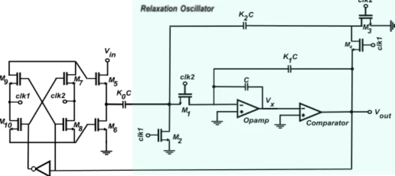
A Voltage Controlled Oscillator Using IGZO Thin-Film Transistors
Texto
Imagem


Documentos relacionados
The greatest difficult in the determination of plasma temperature using a multiple levels approach is overcome by calculating the transition probabilities in terms of the
Dynamical features in dissipation processes have been de- scribed by a simple classical model that contains the essen- tial properties of a surface oscillator interacting with bulk
Cabe ao Farmacêutico perceber quais são as necessidades dos utentes e se a medicação é adequada à patologia em causa, pois muitas das vezes é o Farmacêutico que
Regarding the oscillator tuning range, during the optimization design the varactor control voltage was fixed to 0.4 V. Thus, and assuming that the control voltage var- ies between
In this work, it was used the a-Si Level 61 TFT Model together with genetic algorithms, to model a-IGZO transistors produced, with a gate dielectric deposited by a solution method
Figure 2 shows a block diagram of the RF generator board with the corresponding voltage and current measurement stages. The circuit is composed of: 1) astable oscillator adjusted
Um dos tipos de medidas mais importantes e que é adotado na maioria dos países é o que se pretende apresentar a seguir: medidas relacionadas com os recursos públicos gastos na
Figure 47(b) shows the corresponding oscillator strength as a function of the magnetic field for the same transitions appearing in the left panel. All transitions show an