Repositório ISCTE-IUL
Deposited in Repositório ISCTE-IUL: 2019-05-24
Deposited version: Post-print
Peer-review status of attached file: Peer-reviewed
Citation for published item:
Monteiro, V., Ferreira, J. C., Melendez, A. A. N., Couto, C. & Afonso, J. L. (2018). Experimental validation of a novel architecture based on a dual-stage converter for off-board fast battery chargers of electric vehicles. IEEE Transactions on Vehicular Technology. 67 (2), 1000-1011
Further information on publisher's website: 10.1109/TVT.2017.2755545
Publisher's copyright statement:
This is the peer reviewed version of the following article: Monteiro, V., Ferreira, J. C., Melendez, A. A. N., Couto, C. & Afonso, J. L. (2018). Experimental validation of a novel architecture based on a dual-stage converter for off-board fast battery chargers of electric vehicles. IEEE Transactions on Vehicular Technology. 67 (2), 1000-1011, which has been published in final form at
https://dx.doi.org/10.1109/TVT.2017.2755545. This article may be used for non-commercial purposes in accordance with the Publisher's Terms and Conditions for self-archiving.
Use policy
Creative Commons CC BY 4.0
The full-text may be used and/or reproduced, and given to third parties in any format or medium, without prior permission or charge, for personal research or study, educational, or not-for-profit purposes provided that:
• a full bibliographic reference is made to the original source • a link is made to the metadata record in the Repository • the full-text is not changed in any way
The full-text must not be sold in any format or medium without the formal permission of the copyright holders.
Serviços de Informação e Documentação, Instituto Universitário de Lisboa (ISCTE-IUL) Av. das Forças Armadas, Edifício II, 1649-026 Lisboa Portugal
Phone: +(351) 217 903 024 | e-mail: [email protected] https://repositorio.iscte-iul.pt
Abstract—The experimental validation of a novel architecture
of an off-board, three-phase fast battery charger for electric vehicles (EVs) with innovative operation modes is presented in this paper. The proposed EV fast battery charger is based on a dual-stage power converter (ac-dc and dc-dc) sharing the same dc-link. The ac-dc stage is used as an interface between the power grid and the dc-link. It is composed of the parallel association of two full-bridge voltage-source converters, and allows control of the grid current and of the dc-link voltage. The dc-dc stage is used as an interface between the dc-link and the batteries. It is constituted by a bidirectional three-level asymmetrical voltage-source converter, and controls the flux of current during the EV battery charging process. Compared with the traditional solutions used for EV fast battery chargers, the proposed architecture operates as an interleaved converter, facilitating the reduction of the passive filters size and the grid current harmonic distortion for the same switching frequency. Throughout the paper, the ac-dc and dc-dc stages, and the digital control algorithms are described in detail. The experimental validation was performed in a laboratory using a developed EV fast battery charger prototype, operating through the grid-to-vehicle (G2V) and the proposed charger-to-grid (C2G) modes, exchanging active and reactive power with the power grid.
Index Terms—Electric Vehicle, Digital Control, Fast Battery
Charger, Interleaved Converter, Predictive Current Control.
I. INTRODUCTION
OWADAYS, electric mobility represents the main contribution to increase sustainability and efficiency in the transport sector [1][2][3]. Moreover, it can also be integrated with renewables for energy management in smart
Copyright (c) 2015 IEEE. Personal use of this material is permitted. However, permission to use this material for any other purposes must be obtained from the IEEE by sending a request to [email protected].
Vítor Monteiro, Carlos Couto, and João L. Afonso are with Centro Algoritmi, University of Minho, Department of. Industrial Electronics, 4800-058 Guimarães, Portugal; emails: [email protected], [email protected] and [email protected]. (corresponding author phone: +351 253 510 392; e-mail: [email protected]).
João Ferreira is with Centro Algoritmi, University of Minho and Instituto Universitário de Lisboa (ISCTE-IUL), Information Sciences Technologies and Architecture Research Center (ISTAR-IUL), Portugal; e-mail: [email protected].
Andrés Nogueiras is with Departamento de Tecnología Electrónica, University of Vigo, Vigo, 36310, Spain; email: [email protected].
grids [4][5]. In this context, an overview of the present status and future trends for electric vehicle (EV) propulsion technologies is presented in [6]. In order to illustrate the benefits of electric mobility, a comparison between an EV and a diesel powered vehicle is presented in [7]. Nevertheless, for full adoption of EVs, it is necessary to adopt effective control strategies for their integration according to the new paradigms of microgrids, smart grids and smart homes [8][9][10]. Some of these strategies are related with power quality issues and the time required to perform the battery charging process, which represents one of the main issues that must be addressed by EV chargers [11][12]. To perform the battery charging process, on-board chargers (typically slow chargers) or off-board chargers (typically fast chargers) can be used. For both solutions, advantages and disadvantages can be identified [13]. Taking into account that the EV battery charging process from the power grid requires the conversion of ac voltages to dc voltages, the main solutions are based on passive (e.g., 12-pulse diode rectifier [14]) or active power converters (e.g.,
VIENNA, SWISS, and neutral-point-clamped converters [15][16]), and one-stage or two-stage converters [14][17].
In this context, this paper proposes a novel architecture of an off-board three-phase EV fast battery charger based on a dual-stage converter. The first stage (ac-dc) is used as an interface between the power grid and the dc-link and is composed of the parallel of two full-bridge voltage-source converters. Therefore, these converters can operate in interleaved mode, i.e., the resulting frequency is double the switching frequency of each converter. The second stage (dc-dc) is used as an interface between the dc-link and the batteries and is composed of a bidirectional three-level asymmetrical voltage-source converter. Operation of this dc-dc converter is similar to an interleaved converter, i.e., it is controlled with one single controller at one switching frequency, and the resulting frequency in the coupling filter is double the switching frequency. The digital control algorithm for both ac-dc and dc-dc stages is implemented in the digital signal processor (DSP) TMS320F28335 from Texas Instruments.
Besides the grid-to-vehicle (G2V) operation mode [18], using dedicated EV battery chargers, the EV emerges with several opportunities and challenges for power grids and for
Experimental Validation of a Novel Architecture
Based on a Dual-Stage Converter for Off-Board
Fast Battery Chargers of Electric Vehicles
Vítor Monteiro, Student Member, IEEE, João C. Ferreira, Senior Member, IEEE, Andrés A. Nogueiras Melendez, Member, IEEE, Carlos Couto, Senior Member, IEEE,and João L. Afonso, Member, IEEE
the EV user [19][20]. Some of these opportunities and challenges are related to the vehicle-to-home (V2H), vehicle-to-vehicle (V2V), and vehicle-to-grid (V2G) operation modes [21][22]. Besides these operation modes, the EV battery charger can also be used to mitigate power quality problems [23][24]. In this context, to compensate zero sequence current, caused by load imbalance or triplen harmonics, it is necessary to use a four-wire interface with the power grid (like the architecture proposed in this paper, c.f. Fig. 1). This paper also proposes use the off-board EV fast battery charger to mitigate power quality problems associated with the low power factor (due to reactive power) in the same electrical installation. In this operation mode, only the ac-dc stage of the charger is used (without using the stored energy in the batteries), and therefore it is proposed in this paper as charger-to-grid (C2G) mode.
Compared to traditional converters used for off-board EV fast battery chargers, the main contributions of this paper are: Architecture that can obtain sinusoidal grid currents even with distorted power grid voltages, and compared to the traditional active rectifiers it is possible to reduce the grid current error, reduce the passive filters for the same switching frequency, enhance the redundancy of the system, and reduce the grid current harmonic distortion [25] (cf. a detailed comparative analysis in section II.C); Experimental validation of the G2V operation mode and the possibility to operate in bidirectional mode, i.e., through the V2G operation mode (delivering part of the stored energy in the batteries back to the power grid); Experimental validation of the off-board EV battery charger operating in the G2V mode combined with the C2G mode, producing inductive or capacitive reactive power aiming to mitigate power quality problems.
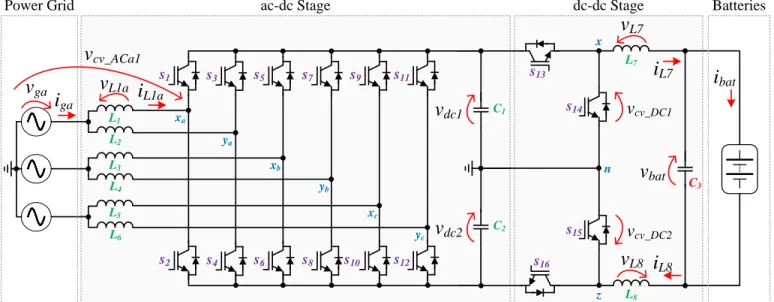
The proposed dual-stage architecture for off-board EV fast battery chargers is shown in Fig. 1. As can be seen, this novel architecture is non-isolated, since it is only mandatory to guarantee galvanic isolation between the traction batteries and the vehicle chassis according to the IEC 61851-1 standard [26]. The topologies for isolated and non-isolated EV battery
chargers are presented in [27] and [28]. Some structures of non-isolated fast battery chargers are presented in [29], [30], [31], and [32].
The rest of this paper is structured as follows. Section II presents a detailed description of the EV fast battery charger (principle of operation for both ac-dc and dc-dc stages), and a comparative analysis with the main alternative converters for off-board EV battery chargers. The digital control algorithm is presented in section III and the experimental verification is presented in section IV. Finally, section V presents the main conclusions.
II. PROPOSED ARCHITECTURE OF FAST BATTERY CHARGER FOR EVS:PRINCIPLE OF OPERATION
The proposed architecture of a fast battery charger for EVs is composed of two power stages: an ac-dc and a dc-dc. Both stages were projected to allow a traditional EV fast battery charging process [33].
A. First Power Stage (ac-dc)
The ac-dc stage is composed of the parallel of two three-phase voltage-source converters. This converter is composed of six legs (twelve IGBTs) and is connected to the power grid through inductive filters. For phase a, the voltage produced by the converter, i.e., voltage vcv_ACa1 (measured between points xa and n) and vcv_ACb1 (measured between points ya and n) can assume two distinct values (-vdc and +vdc), in both positive (vga > 0) and negative (vga < 0) half-cycles of the power grid voltage. It is important to note that vdc is the sum of vdc1 with vdc2. The same reasoning is applied for phases b and c. It is important to note that the sum of these two voltages (vcv_ACa1 and vcv_ACb1) results in a voltage with three levels (-vdc, 0, and +vdc). The phase-to-phase voltage can assume three different values: +vdc, 0, and -vdc. Analyzing the voltage between points xa and xb (vcv_ACab1), when voltage vga is greater than voltage vgb, the voltage produced by the converter can assume two distinct values (0 and +vdc) and when voltage
vga is lower than voltage vgb the voltage produced by the
Fig. 1. Proposed architecture for the three-phase EV fast battery chargers. s2 s1 s6 s5 s10 s9 s4 s3 s8 s7 s12 s11 s16 s13 s15 s14 L7 C3 C2 C1 L1 L2 L3 L4 L5 L6
Power Grid ac-dc Stage dc-dc Stage Batteries
v
gav
dc1v
dc2i
L7i
L8i
batv
bat x z n xa ya xb yb xc ycv
L1ai
L1av
L7 L8v
L8i
gav
cv_DC1v
cv_DC2v
cv_ACa1converter can also assume two values (0 and -vdc). B. Second Power Stage (dc-dc)
The dc-dc stage is a bidirectional three-level asymmetrical converter. This converter is composed of four IGBTs and a second-order LC filter. Through a proper control algorithm this converter operates with features similar to an interleaved mode, i.e., controlled with one single controller at one switching frequency, and the resulting frequency is double. During the G2V operation mode, this converter operates as a buck-type converter and during the V2G operation, it operates as a boost-type converter. During the G2V operation mode, the anti-parallel diodes of the IGBTs s14 and s15 are used. When the IGBT s13 is on, voltage vcv_DC1 (voltage between points x and n identified in Fig. 1) is +vdc/2, and when the IGBT s13 is off, voltage vcv_DC1 is 0. When the IGBT s16 is on, voltage vcv_DC2(voltage between points z and n identified in Fig. 1) is +vdc/2, and when the IGBT s16 is off, voltage vcv_DC2 is 0. When both IGBTs s13 and s16 are on, then the voltages
vcv_DC1 and vcv_DC2 are +vdc/2. When both IGBTs s13 and s16 are
off, the voltages vcv_DC1 and vcv_DC2 are 0. During the V2G operation mode the anti-parallel diodes of the IGBTs s13 and
s16 are used. When the IGBT s14 is on, voltage vcv_DC1 is +vdc/2,
and when the IGBT s14 is off, voltage vcv_DC1 is 0. When the IGBT s15 is on, voltage vcv_DC2 is +vdc/2, and when the IGBT
s15 is off, voltage vcv_DC2 is 0. When both IGBTs s14 and s15 are
on, then the voltages vcv_DC1 and vcv_DC2 are +vdc/2. When both IGBTs s14 and s15 are off, the voltages vcv_DC1 and vcv_DC2are 0. C. Comparative Analysis
This item presents a comparative analysis, based on computer simulations using PSIM software, between the presented and the traditional solutions for off-board EV fast battery chargers aiming to highlight the benefits of the proposed architecture.
1) Ac-Dc Front-End Converter
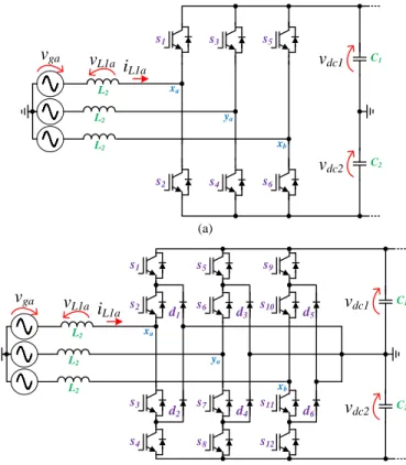
For the ac-dc converter, a comparison was made between the traditional full-bridge full-controlled converter composed of 6 IGBTs, i.e., a 6-switch topology (6S) [34], the neutral-point-clamped converter (NPC) composed of 12 IGBTs and 6 diodes [35], and the proposed interleaved converter (INT) composed of 12 IGBTs (cf. Fig. 1). These converters are shown respectively, in Fig. 2(a) and Fig. 2(b). The maximum voltage applied to the IGBTs of the 6S and INT converters is vdc, and the maximum voltage applied to the IGBTs or diodes of the NPC is vdc/2. Although the voltage applied to the IGBTs of the NPC is half of the voltage applied to the IGBTs of the interleaved converter, the rms value of the current in the IGBTs of the interleaved converter is at least about 60% lower. Fig. 3 shows, in 100 µs detail, the grid current of the three converters under comparison (6S, NPC, INT) for an operating power of 40 kW. For the same conditions of operation, the grid current of the interleaved converter has the smallest ripple. Moreover, the ripple has double the frequency of the other converters. Analyzing each phase individually, the proposed converter operates similarly to an active rectifier switched by a unipolar PWM, i.e., the
frequency in the ripple of the resultant current is double the switching frequency.
2) Dc-Dc Back-End Converter
For the dc-dc converter, a comparison was made between
Fig. 2. Front-end ac-dc converters: (a) 6 switch topology (6S); (b) Neutral point clamped converter (NPC).
Fig. 3. Comparison, in 100 µs detail, of the grid current for the three converters under comparison (6S, NPC, INT) operating with a power of 40 kW.
Fig. 4. Comparison, in 150 µs detail, between the current in the output inductance of the two converters under comparison (HB, TLA) for an operating power of 40 kW. (a) (b) s2 s1 s6 s5 s4 s3 C2 C1 vga vdc1 vdc2 xa ya xb L2 vL1a i L1a L2 L2 s4 s1 s12 s9 s8 s5 C2 C1 vga vdc1 vdc2 xa ya xb s2 s6 s10 s3 s7 s11 L2 vL1a i L1a L2 L2 d1 d2 d3 d4 d5 d6 -4 -2 0 2 4 0.00995 0.01000 0.01005 Curr ent ( A) Time (s) -4 -2 0 2 4 0.00995 0.01000 0.01005 C ur rent ( A ) Time (s) -4 -2 0 2 4 0.00995 0.01000 0.01005 C ur ren t (A ) Time (s) 57 58 59 0.00495 0.00500 0.00505 C ur rent ( A ) Time (s)
i
ga (INT)i
ga (NPC)i
ga (6S) 20 kHz 20 kHz 40 kHz 80 100 120 0.00400 0.00405 0.00410 0.00415 C ur rent ( A ) Time (s) 80 100 120 0.00400 0.00405 0.00410 0.00415 Curr ent ( A) Time (s) 80 100 120 0.00400 0.00405 0.00410 0.00415 C ur rent ( A ) Time (s) 40 kHz 20 kHzi
L7 (HB)i
L7 (TLA)the traditional bidirectional half-bridge (HB) converter [36], and the aforementioned bidirectional three-level asymmetrical (TLA) converter. Fig. 4 shows in 150 µs detail the current of the two converters under comparison for an operating power of 40 kW, where the current of the three-level asymmetrical converter has the smallest ripple and the ripple has double the frequency of the other converter.
III. DIGITAL CONTROL ALGORITHM
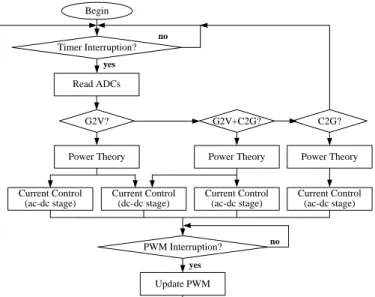
The flowchart of the digital control algorithm, for both ac-dc and dc-dc stages, is in Fig. 5. The Fig. 6 is the block diagram, and Table I shows the time required to perform the main tasks of the digital control algorithm. The PLL synchronization is the task that requires most time, and
reading the ADCs requires the smallest time. As expected, the digital implementation of predictive current for the ac-dc stage requires more time than for the for the dc-dc stage. These times were measured using one of the features available in the Code Composer Studio from Texas Instruments, i.e., the software used to program the DSP TMS320F28335 (cf. Section IV.A). In the scope of this paper, a predictive current control strategy is used, because it is desired, and thus possible, to achieve minimum current ripple and nearly zero current error. The predictive current control technique consists of determining the voltage that the converter must synthesize in a sample instant [k] (that is maintained during the period [k, k+1]) for the produced current to reach its reference after some samples [37][38].
A. Control Method for the First Power Stage (ac-dc)
The ac-dc stage is used to control the grid current and to control the dc-link voltage. Since this converter should operate with sinusoidal grid currents, it is necessary to use sinusoidal references in phase with the power grid voltages. For this purpose, a power theory is used to establish the current references based on the power grid voltage and the operating power, i.e., the EV fast battery charger is seen as an equivalent conductance (GEV). Therefore, the instantaneous grid current references can be established according to:
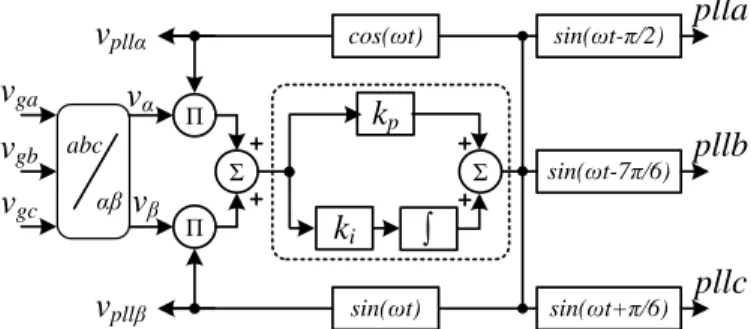
𝑖𝑔{𝑎,𝑏,𝑐}∗(t) = 𝐺𝐸𝑉(𝑡)𝑣𝑔{𝑎,𝑏,𝑐}(𝑡) , (1) where, a, b and c represent the grid currents or voltages of phases a, b and c. Using the equation (1), it is possible to obtain sinusoidal grid current references presenting the same waveforms of the grid voltages. In this situation, it is possible to obtain constant power from the power grid. However, nowadays, due to nonlinear electrical appliances and line impedances, distorted currents produce distorted grid voltages. In this case, it is not possible to obtain constant power from the power grid or sinusoidal grid currents, which can cause power quality problems. To overcome this drawback, instead of using the power grid voltage directly, a signal only proportional to its fundamental component is used. This signal is obtained using a phase-locked loop algorithm implemented in αβ coordinates (αβ-PLL) [35] and the rms value of the power grid voltages. It is important to note that other strategies can be applied to synchronize the converter with the fundamental component of the power grid voltage [40][41][42]. Some of these strategies are linear and pseudolinear enhanced PLL, where it is possible to estimate and reject several undesirable harmonics [43], and the adaptive band-pass filter which is mainly focused on highly distorted and unbalanced signals [44]. The algorithm of this αβ-PLL is shown in Fig. 7, where the signals vpllα and vpllβ are the feedback signals that are compared with vα and vβ obtained from the Clarke transformation applied to the power grid voltages. The resulting error is used in a PI controller to obtain the phase angle ωt. Then, ωt is used to obtain three signals with unitary amplitude (plla, pllb, pllc) that are multiplied by the rms value of each power grid voltage to obtain three signals that correspond only to the fundamental component of
Fig. 5. Flowchart of the digital control algorithm.
Fig. 6. Block diagram of the digital control algorithm. TABLE I
TIME REQUIRED BY THE MAIN TASKS OF THE DIGITAL CONTROL ALGORITHM
Tasks Value Unit
Reading ADCs 526 ns
PLL Synchronization 2960 ns
Digital Filter (dc-link voltage) 1342 ns
Power Theory 1847 ns
Predictive Current Control (ac-dc stage) 2687 ns Predictive Current Control (dc-dc stage) 1707 ns
Begin Read ADCs Power Theory Update PWM no yes no Current Control (ac-dc stage) Current Control (dc-dc stage) yes Timer Interruption? PWM Interruption? G2V+C2G? C2G? G2V?
Power Theory Power Theory
Current Control (ac-dc stage) Current Control (ac-dc stage) dc-link voltage control ac-dc PWM dc-dc PWM 3 phase GEV eq.(5) eq.(2) current control eq.(12) current iev* eq.(9) va vb vc vdc* vdc1 vdc2 vbat ibat vbat ibat Q* current control eq.(6) current iev* vbat* ibat* s1 .. .s1 2 s13...s16 fig.(7) voltage PLL
the power grid voltages (vpll_sa, vpll_sb, vpll_sc). With this strategy, it is possible to obtain sinusoidal grid currents even with distorted power grid voltages contributing to preserving the power quality. Consequently, equation (1) can be rearranged as:
𝑖𝑔{𝑎,𝑏,𝑐}∗(t) = 𝐺𝐸𝑉(𝑡)𝑣𝑝𝑙𝑙_𝑠{𝑎,𝑏,𝑐}(𝑡) . (2) The signal GEV can be divided in three components, one for each phase, according to:
𝐺𝐸𝑉{𝑎,𝑏,𝑐}(t) =
𝑃𝐸𝑉{𝑎,𝑏,𝑐}(t) 𝑉𝐺{𝑎,𝑏,𝑐}2(t)
, (3)
where VG{a,b,c} corresponds to the rms value of each single-phase power grid voltage, and PEV{a,b,c} represents the operating power of the EV fast charger according to:
𝑃𝐸𝑉{𝑎,𝑏,𝑐}(t) = 𝑃𝐷𝐶(𝑡) + 𝑃𝐵𝐴𝑇(𝑡) , (4) where PDC is the power to regulate the dc-link voltage and
PBAT the power to charge the batteries, i.e., the operating
power of the dc-dc stage. The three-phase GEV signal is defined according to:
𝐺𝐸𝑉(t) = 𝑃𝐸𝑉𝑎(t)𝑃𝐸𝑉𝑏(t) 𝑉𝐺𝑎2(t)𝑉𝐺𝑏2(t)𝑉𝐺𝑐2(t) + (5) + 𝑃𝐸𝑉𝑏(t)𝑃𝐸𝑉𝑐(t) 𝑉𝐺𝑎2(t)𝑉𝐺𝑏2(t)𝑉𝐺𝑐2(t) + + 𝑃𝐸𝑉𝑐(t)𝑃𝐸𝑉𝑎(t) 𝑉𝐺𝑎2(t)𝑉𝐺𝑏2(t)𝑉𝐺𝑐2(t) .
Taking into account that the proposed EV battery charger can also operate in the C2G mode, the final control equation defining the grid current reference for each phase is established according to:
𝑖𝑔{𝑎,𝑏,𝑐}∗(t) = 𝐺𝐸𝑉(𝑡)𝑣𝑝𝑙𝑙_𝑠{𝑎,𝑏,𝑐}(𝑡) +
(6) + 𝑄{𝑎,𝑏,𝑐}
∗
𝑉𝐺{𝑎,𝑏,𝑐}2(t)𝑣𝑝𝑙𝑙_𝑐{𝑎,𝑏,𝑐} .
where, Q* denotes the reactive power reference, and vpll_c{a,b,c} the quadrature output signals from the PLL, i.e., output signals with a phase-shift of 90 degrees in relation to vpll_s{a,b,c}.
From Fig. 1, analyzing the voltages and currents between the power grid and the converter (leg formed by the IGBTs s1 and s2) it can be established that:
𝑣𝑔𝑎(t) = 𝑣𝐿1(𝑡) + 𝑣𝑐𝑣_𝐴𝐶𝑎1(𝑡) , (7) where vcv_ACa1 is the voltage produced by the converter in phase a (cf. Fig. 1). Substituting the voltage across the
inductance and rearranging equation (7) as a function of the voltage produced by the converter (IGBTs s1 and s2), it can be established:
𝑣𝑐𝑣_𝐴𝐶𝑎1(𝑡) = 𝑣𝑔𝑎(t) − 𝐿1𝑑𝑖𝐿1𝑎(𝑡)
𝑑𝑡 . (8)
In order to use equation (8) in the digital control system, the forward Euler method to discretize the derivative is used. Therefore, digital implementation of the equation (7) in each sampling period [k, k+1] results in:
𝑣𝑐𝑣_𝐴𝐶𝑎1[𝑘] = 𝑣𝑔𝑎[𝑘] −𝐿1
𝑇𝑠(𝑖𝐿1𝑎[𝑘 + 1] − 𝑖𝐿1𝑎[𝑘]) , (9) where Ts is the period of the signal, and k and k+1 are the actual and next samples, respectively. Taking into account that the desired current must follow its reference, the current
iga1[k+1] is replaced by its reference iga1*[k]. During each
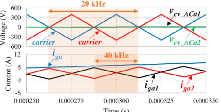
sampling period, a new value of voltage vcv_ACa1 is calculated, which is then compared with a triangular carrier. In our implementation this triangular carrier has a frequency of 20 kHz. Considering that the ac-dc stage is composed of the parallel of two full-bridge voltage-source converters, in the scope of this paper two triangular carriers with a phase angle of 180 degrees between them are used. Using this strategy, the ac-dc stage operates as an interleaved converter, i.e., the frequency of the current ripple in the inductors is 20 kHz, but the resulting frequency of the current ripple in each phase of the power grid is double the switching frequency (40 kHz). The simulation results, obtained with PSIM are depicted in Fig. 8, showing the principle of the ac-dc stage operation, for phase a. This Figure shows the two carriers, the voltage produced by the converter (vcv_ACa1 and vcv_ACa2), the grid currents in each inductance (iga1 and iga2) and the resulting current (iga). In this case, as the duty-cycle is 50% (the voltages are centered-aligned with the carriers), a total ripple cancellation in the resulting grid current (iga) is achieved. A duty-cycle of 50% was selected as a particular case to show the ripple cancellation in the ac current, since the current ripple is influenced by the duty-cycle. Fig. 9 shows the total harmonic distortion (THD%) and the power factor as a function of the operation mode. While the power factor is almost always kept equal to 0.99, the current THD%, as expected, is lower near the nominal power. These results were obtained through computer simulations.
B. Control Method for the Second Power Stage (dc-dc) The dc-dc stage is used to control the battery charging current. The current reference is defined by the battery management system (BMS) according to the batteries’ state-of-charge (SoC). From Fig. 1, analyzing the voltages and currents between the dc-link and the batteries, it can be established that:
𝑣𝑐𝑣_𝐷𝐶1(t) = 𝑣𝐿7(𝑡) + 𝑣𝑏𝑎𝑡(𝑡) , (10) where vbat is the voltage in the batteries and vcv_DC1 is the voltage produced by the converter. Substituting the voltage across the inductance in equation (9), it can be established:
Fig. 7. Block diagram of the three-phase αβ-PLL algorithm.
k
i Σk
p
sin(ωt-π/2) sin(ωt-7π/6) sin(ωt+π/6)plla
sin(ωt) cos(ωt) abc αβv
pllαv
βv
gav
gbv
gc Σ Π Πv
pllβv
αpllb
pllc
𝑣𝑐𝑣_𝐷𝐶1(𝑡) = 𝑣𝑏𝑎𝑡(t) + 𝐿7 𝑑𝑖𝐿7(𝑡)
𝑑𝑡 . (11)
In order to use equation (10) in the digital control system, the forward Euler method to discretize the derivative is applied again. Therefore, digital implementation of the equation (10) results in:
𝑣𝑐𝑣_𝐷𝐶1[𝑘] = 𝑣𝑏𝑎𝑡[𝑘] + 𝐿7
𝑇𝑠(𝑖𝐿7[𝑘 + 1] − 𝑖𝐿7[𝑘]) . (12) The current iL7[k+1] is replaced by its reference iL7*[k] to the produced current iL7[k] following its reference. A new value of the voltage produced by the converter (vcv_DC1) in each sampling period is calculated, and compared with the 20 kHz triangular carrier. Voltage vcv_DC2 is equal to voltage vcv_DC1. In order to obtain a resultant current with double the switching frequency, two triangular carriers are used, with a phase angle of 180 degrees between them. Therefore, the resulting frequency of the current ripple in the inductor L7 is double the switching frequency (40 kHz). Fig. 10 shows simulation results (obtained with PSIM) about the principle of the dc-dc stage operation. This figure shows the two carriers, the voltage produced by the converter (vcv_DC1 and vcv_DC2) and the current in inductor L7 (iL7), which is the same as in inductor L8 (iL8). In
this case, as the duty-cycle is not 50% (the voltage is not centered-aligned with the carriers), a significant ripple in the resulting current (iL7) is observed. A duty-cycle different from 50% was selected for the dc-dc converter, since it is the most common situation, i.e., EV batteries voltage are not always half of the dc-link voltage.
IV. EXPERIMENTAL VERIFICATION
This section presents the development of the off-board EV fast battery charger and the experimental results that were obtained to verify the validity of the proposed architecture and the proposed C2G operation mode [33]. The experimental results were obtained in a laboratory environment for both ac-dc and dc-dc stages using a set of 24 sealed 12 V, 33 Ah Absorbed Glass Mat (AGM) batteries (with nominal voltage of 244 V and nominal capacity of 9.6 kWh). Although the nominal phase-to-phase grid voltage of the three-phase off-board EV fast battery charger is 400 V, the experimental results were obtained with a voltage of 200 V using three single-phase transformers and for an operating power of 7.6 kW due to the experimental setup facility safety. It is important to note that this operating voltage does not invalidate the experimental results obtained or the proposed architecture. This off-board EV battery charger is being used with the EV developed and presented in [45].
A. Developed EV Fast Battery Charger
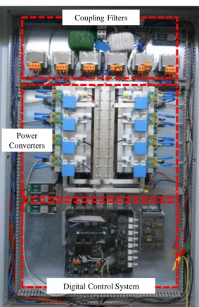
The developed off-board EV fast battery charger is shown in Fig. 11, and the main specifications are shown in Table II. This prototype is divided in two fundamental blocks: the digital control system and the dual-stage power converter. The digital control is mainly composed of circuits for signal acquisition, command and protection, and the dual-stage power converter is mainly composed of IGBT modules, IGBT gate drivers and passive filters.
Signal acquisition is performed using the current transducers LA 100-P from LEM and the voltage transducers CYHVS025A from ChenYang. These signals are adapted from the transducers to the ADC using a signal conditioning circuit, which consists of adding an offset to the bipolar signals, e.g., the grid currents and the power grid voltages. The output signals from the signal conditioning circuit are acquired by the internal ADCs of the DSP TMS320F28335 from Texas Instruments. These signals are acquired with a sampling frequency of 40 kHz. With the digital signals the control equations for both ac-dc and dc-dc stages are implemented, and the output signals for the PWM are obtained. These signals are adapted from the DSP to the IGBT drivers using a command circuit. With this circuit, each signal with a maximum voltage of 3.3 V is converted to a signal with a maximum voltage of 15 V. Combined with this circuit a protection circuit is also used, which compares each signal from the signal conditioning with a threshold in order to detect errors. If any of the signals exceeds the threshold, then an error is identified and the PWM signals are interrupted. For this purpose, logic circuits implemented with AND gates are used. The outputs from the command circuit (PWM signals)
Fig. 8. Principle of operation for phase a of the ac-dc stage: Voltage produced by the converter (vcv_ACa1, vcv_ACb1); Grid current in each inductance (iga1, iga2);
Resulting grid current (iga).
Fig. 9. THD% and power factor as a function of the operation power.
Fig. 10. Principle of operation of the dc-dc stage: Voltage produced by the converter (vcv_DC1); Current in the inductor IL7 (iL7).
-6 0 6 12 0.000250 0.000275 0.000300 0.000325 0.000350 C ur rent ( A ) Time (s) -600 -300 0 300 600 0.000250 0.000275 0.000300 0.000325 0.000350 V ol tag e (V ) Time (s) 20 kHz 40 kHz
i
ga1i
ga2i
gav
cv_ACa1v
cv_ACa2 carrier carrier 5 kW; 7.1% 10 kW; 3.6% 15 kW; 2.4% 20 kW; 1.8% 25 kW; 1.4% 30 kW; 1.2% 35 kW; 1.1% 40 kW; 0.9% 0.5 0.7 0.9 1.1 0 % 2 % 4 % 6 % 8 % 0 kW 10 kW 20 kW 30 kW 40 kW Powe r Fa ct or T HD 88 96 104 112 0.000250 0.000275 0.000300 0.000325 0.000350 Cur re nt ( A) Time (s) -200 200 600 1000 0.000250 0.000275 0.000300 0.000325 0.000350 V ol tag e (V ) Time (s) 20 kHz 40 kHzi
L7v
cv_DC1v
cv_DC2 carrier carrierare connected to the IGBT gate drivers, i.e., the model SKHI 22AH4 R from Semikron (each one of these drivers can control two IGBTs). For the IGBTs the modules model SKM 100GB125DN, also from Semikron are used (each module has two IGBTs with the respective diode). It is important to note that the EV battery charger was developed using IGBTs, which is a robust and mature technology for industrial applications. However, in the next years it is expected to use power electronics solutions based mainly on SiC power devices, aiming to increase efficiency.
B. Experimental Results
This item presents the main experimental results obtained with the proposed architecture of the EV fast battery charger. These results, obtained with the Yokogawa DL708E oscilloscope, show separately the details of the operation of both ac-dc and dc-dc stages, and the combined operation of both stages, i.e., controlling the grid current (iga, igb, igc), the dc-link voltage (vdc), and the battery charging current (ibat). It
is important to mention that the experimental results were obtained to validate the principle of operation, the power theory, and the current control algorithms of the proposed architecture, as well as the proposed C2G operation mode. 1) Grid-to-Vehicle (G2V) Operation Mode
For phase a of the ac-dc stage, Fig. 12 shows in detail the current through inductors L1 (iL1a) and L2 (iL2a) and the resulting grid current iga, i.e., the sum of the currents on the inductors. As can be seen, the current in each inductor has a switching frequency of 20 kHz and a ripple of 0.6 A. These experimental results show that for a duty-cycle of about 50%, the ripple in the grid current is almost totally cancelled out (cf. Fig. 8).Fig. 13 also shows the current in inductors L1 (iL1) and L2 (iL2), but during one cycle of the power grid voltage. This figure also shows the voltage produced by the ac-dc stage (vcv_ACab1) between phases a and b of one full-bridge converter (cf. the voltage between points xa and ya identified in Fig. 1). As predicted, the currents through the inductors are sinusoidal and overlap. Moreover, in this figure, the phase angle (30
Fig. 11. Experimental setup developed for the experimental verification. TABLE II
EVFAST BATTERY CHARGER SPECIFICATIONS.
Parameters Value Unit
Grid Voltage (phase-to-phase) 400 ± 10% V
Grid Frequency 50 ± 1% Hz
THD%i @ Full Load < 3%
Total Power Factor @ Full Load 0.99
Output dc Voltage Range 200 to 500 V
Maximum Output Current 100 A
Maximum Output Power 40 kW
Dc-link Capacitors C{1,2} 2.6 mF
Input Inductors L{1,…,6} 2 mH
Output Inductors L{7,8} 130 µH
Coupling Filters
Digital Control System Power
Converters
Fig. 12. Experimental results for phase a of the ac-dc stage: Current in inductors L1 (iL1: 0.2 A/div) and L2 (iL2: 0.2 A/div); Resulting grid current (iga:
0.5 A/div).
Fig. 13. Experimental results for phase a of the ac-dc stage: Voltage produced by the converter between phase a and b (vcv_ACab1: 200 V/div); Current in
inductors L1 (iL1: 1 A/div) and L2 (iL2: 1 A/div); Resulting grid current (iga:
1 A/div).
i
L1ai
L2ai
gai
L2ai
L1av
cv_ACab130º
degrees) between the currents in the inductors (current in phase a) and the voltage produced by the converter between phases a and b, is observed. This voltage is shown in detail in Fig. 14, where the currents in the inductors are also shown.
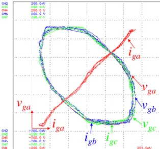
For the experimental validation of the ac-dc stage, Fig. 15 shows the three power grid voltages (vga, vgb, vgc) and the three grid currents (iga, igb, igc). These experimental results were obtained to show that the grid currents are balanced and sinusoidal even with distorted power grid voltages. Fig. 16 shows the grid current in phase a (iga) as a function of the power grid voltage in phase a (vga) (X-Y mode). This figure also shows the grid current in phase a (iga) as a function of the grid current in the other phases (igb and igc) as well as a function of the power grid voltage in phases b and c (vga and
vgb). Analyzing these experimental results, it is possible to
observe that, for the phase a, the relation between the grid current (iga) and the power grid voltage (vga) is nonlinear. This nonlinearity is more evident in the maximum values, where the power grid voltage (vga) is distorted and the grid current (iga) is sinusoidal (cf. Fig. 15).
For the experimental validation of the dc-dc stage, Fig. 17
shows the current in inductor L7 (IL7) (which is the same current as in inductor L8), and the gate-emitter voltages applied to the IGBTs s13 (vge_s13) and s16 (vge_s16) (cf. Fig. 1). As can be observed, the switching frequency of each IGBT is 20 kHz and the IGBTs are switched interchangeably. Therefore, the resulting frequency of the current ripple in the inductor (L7 and L8) is 40 kHz. These experimental results were obtained to show the correct operation of the dc-dc stage as an interleaved converter.
Combining both ac-dc and dc-dc stages, Fig. 18 shows the experimental results of the variables that are controlled during operation of the proposed architecture of a fast battery charger for EVs. As mentioned, the ac-dc stage controls the amplitude of the grid currents (iga, igb, igc) and the dc-link voltage (vdc), and the dc-dc stage controls the current during the battery charging process. In this case, the grid currents are controlled for a maximum current of 30 A per phase, the dc-link voltage is properly controlled for 400 V, and the battery charging current for 17.5 A.
Fig. 14. Experimental results for phase a of the ac-dc stage in detail: Voltage produced by the converter between phases a and b (vcv_ACab1: 200 V/div);
Current in inductors L1 (iL1: 2 A/div) and L2 (iL2: 2 A/div).
Fig. 15. Experimental results of the ac-dc stage: Power grid voltages (vga, vgb,
vgc: 50 V/div); Grid currents (iga, igb, igc: 10 A/div).
i
L1ai
L2av
cv_ACab1v
gav
gbv
gci
gci
gai
gbFig. 16. Experimental results: Grid current (iga) as a function of the power grid
voltage (vga) (X-Y mode); Grid current (iga) as a function of the other currents
(igb, igc) and as a function of the other power grid voltages (vgb, vbc) (X-Y
mode).
Fig. 17. Experimental results of the dc-dc stage: Current in inductor L7 (iL7:
2 A/div); Gate-emitter voltages in the IGBTs s13 (vge_s13: 5 V/div) and s16
(vge_s16: 5 V/div).
v
gai
gai
gai
gbv
gav
gbv
gci
gci
L7v
ge_S13v
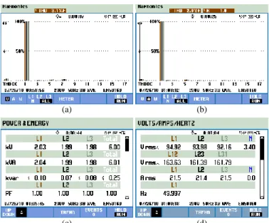
ge_S16The spectral analysis and the THD% of the power grid voltages (vga, vgb, vgc) and the grid currents (iga, igb, igc) are shown, respectively, in Fig. 19(a) and Fig. 19(b). These results were obtained with a Fluke 435 Power Quality Analyzer. The THD% measured for the power grid voltages was 3.1% and for the grid currents 2.0%. These values lead to the conclusion that the grid currents are well controlled and sinusoidal, even with distorted power grid voltages. The operating power and the rms values of these variables are shown, respectively, in Fig. 19(c) and Fig. 19(d). Taking into account that the power grid voltages are unbalanced and the grid currents are balanced, the measured power is unbalanced. It is important to note that the measured power factor was 1.0 for all three phases (cf. Fig. 19(c)). These experimental data demonstrate that the grid currents are synthesized according to the references (obtained from the control algorithms) to be in phase with the power grid voltages.
2) Charger-to-Grid (C2G) Operation Mode
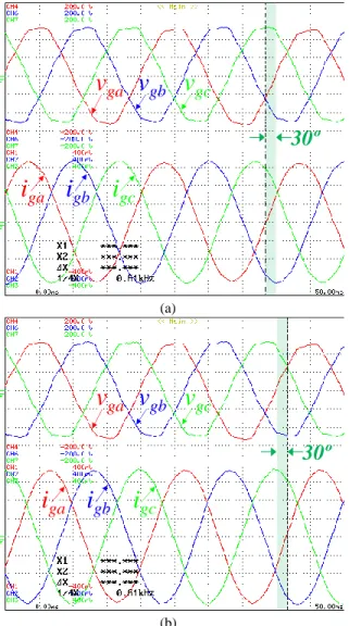
Besides the traditional G2V operation mode, this paper proposes the use of the off-board EV fast battery charger to produce inductive or capacitive reactive power during the fast charging process, called C2G. The power grid voltages (vga,
vgb, vbc) and the grid currents (iga, igb, ibc) in Fig. 20(a) were
measured under operation in capacitive reactive power mode, with an active power of 7.6 kW and a capacitive reactive power of 4.4 kVAr. On the other hand, Fig. 20(b) shows the same voltages and currents, but for operation with production of inductive reactive power. This new operation mode is more relevant considering that the EV fast charging process requires use of the off-board charger for only 30 minutes, and during the charging process, the power demanded is not constant. Therefore, the off-board EV battery charger can take a leading role in the location where it is installed, contributing to mitigating power quality problems associated with lower power factor.
C. Discussion
As expected, the experimental results confirm the correct operation of the proposed dual-stage converter for off-board fast battery chargers of electric vehicles. Despite the number of IGBTs required, the ac current is sinusoidal with lower THD than traditional solutions based on the full-bridge six-leg converter. Additionally, it is possible to confirm that the dc current has a lower ripple to charge the batteries compared with the traditional step-down converter used in EV battery chargers. Moreover, compared against the traditional dc-dc interleaved converter, it requires the same number of IGBTs, but is a three-level structure. A more comprehensive and detailed comparison is presented in section II.C.
As experimentally validated, besides the battery charging process, the proposed dual-stage converter can also produce reactive power. This is very relevant taking into account that the EV charger can contribute to grid voltage stabilization at any moment, with or without any EV plugged in to perform the charging process (cf. section IV.B).
V. CONCLUSIONS
This paper presents a novel architecture of an off-board dual-stage converter for electric vehicles’ (EVs) fast battery chargers. The proposed architecture is composed of two stages sharing the same dc-link, one to interface the power grid and the other to interface the batteries. This novel architecture was experimentally verified in a laboratory environment, where the results obtained validate the proposed digital control algorithm and the dual-stage converter. The experimental results show that it is possible to obtain sinusoidal grid currents and a unitary power factor even with distorted power grid voltages. Moreover, thanks to the predictive current control, the grid current has a THD% value of 2.0%. The experimental results presented were obtained to validate the correct operation of the developed dual-stage architecture. Experimental verification was performed through the grid-to-vehicle (G2V) operation mode, where the batteries are charged from the power grid, and through the proposed charger–to-grid (C2G)
Fig. 18. Experimental results: Grid currents (iga, igb, igc: 10 A/div); Dc-link
voltage (vdc: 200 V/div); Battery charging current (ibat: 4 A/div).
Fig. 19. Experimental results: (a) Spectral analysis and THD% of the power grid voltages; (b) Spectral analysis and THD% of the grid currents (iga, igb, igc);
(c) Operating power for each phase; (d) Rms values for each phase.
i
gci
gai
gbv
dci
bat (a) (b) (c) (d)operation mode, where the ac-dc converter of the battery charger is also used to produce capacitive or inductive reactive power without using energy from the batteries.
VI. ACKNOWLEDGMENT
This work has been supported by FCT – Fundação para a Ciência e Tecnologia in the scope of the project: PEst-UID/CEC/00319/2013. This work has been supported by COMPETE: POCI-01-0145-FEDER-007043 and FCT – Fundação para a Ciência e Tecnologia within the Project Scope: UID/CEC/00319/2013. This work is financed by the ERDF – European Regional Development Fund through the Operational Programme for Competitiveness and Internationalisation ‐ COMPETE 2020 Programme, and by National Funds through the Portuguese funding agency, FCT ‐ Fundação para a Ciência e a Tecnologia, within project SAICTPAC/0004/2015‐ POCI‐ 01‐0145‐FEDER‐016434.
REFERENCES
[1] Wencong Su, Habiballah Rahimi-Eichi, Wente Zeng, Mo-Yuen Chow, “A Survey on the Electrification of Transportation in a Smart Grid Environment,” IEEE Trans. Ind. Informat., vol.8, no.1, pp.1-10, Feb.
2012.
[2] C. C. Chan, “The State of the Art of Electric, Hybrid, and Fuel Cell Vehicles,” Proc. IEEE, vol.95, no.4, pp.704-718, Apr. 2007.
[3] João C. Ferreira, Vítor Monteiro, José A. Afonso, João L. Afonso, “Mobile Cockpit System for Enhanced Electric Bicycle Use,” IEEE Trans. Ind. Informat., vol.11, no.5, pp.1017-1027, Oct. 2015.
[4] Jun Hua Zhao, Fushuan Wen, Zhao Yang Dong, Yusheng Xue, Kit Po Wong, “Optimal Dispatch of Electric Vehicles and Wind Power Using Enhanced Particle Swarm Optimization,” IEEE Trans. Ind. Informat., vol.8, no.4, pp.889-899, Nov. 2012.
[5] Fabian Kennel, Daniel Görges, Steven Liu, “Energy Management for Smart Grids With Electric Vehicles Based on Hierarchical MPC,” IEEE Trans. Ind. Informat., vol.9, no.3, pp.1528-1537, Aug. 2013.
[6] Kaushik Rajashekara, “Present Status and Future Trends in Electric Vehicle Propulsion Technologies,” IEEE J. Emerg. Sel. Topics Power Electron., vol.1, no.1, pp.3-10, Mar. 2013.
[7] J. Martins, F. P. Brito, D. Pedrosa, Vítor Monteiro, João L. Afonso, “Real-Life Comparison between Diesel and Electric Car Energy Consumption,” in Grid Electrified Vehicles: Performance, Design and Environmental Impacts, 1st ed., Carla Alexandra Monteiro da Silva, Ed. Nova Science Publishers, 2013, Chapter 10, pp.209-232.
[8] Changsong Chen, Shanxu Duan, “Optimal Integration of Plug-In Hybrid Electric Vehicles in Microgrids,” IEEE Trans. Ind. Informat., vol.10, no.3, pp.1917-1926, Aug. 2014.
[9] Vehbi C. Gungor, Dilan Sahin, Taskin Kocak, Salih Ergut, Concettina Buccella, Carlo Cecati, Gerhard P. Hancke, “Smart Grid and Smart Homes - Key Players and Pilot Projects,” IEEE Ind. Electron. Mag., vol.6, pp.18-34, Dec. 2012.
[10] Vítor Monteiro, J. G. Pinto, João L. Afonso, “Operation Modes for the Electric Vehicle in Smart Grids and Smart Homes: Present and Proposed Modes,” IEEE Trans. Veh. Tech., vol.65, no.3, pp.1007-1020, Mar. 2016.
[11] J. Carlos Gómez, Medhat M. Morcos, “Impact of EV Battery Chargers on the Power Quality of Distribution Systems,” IEEE Trans. Power Del., vol.18, no.3, pp. 975-981, July 2003.
[12] Shyh-Jier Huang, Bo-Ge Huang, Fu-Sheng Pai, “Fast Charge Strategy Based on the Characterization and Evaluation of LiFePO4 Batteries,” IEEE Trans. Power Electron., vol.28, no.4, pp.1555-1562, Apr. 2013. [13] Charles Botsford, Adam Szczepanek, “Fast Charging vs. Slow
Charging: Pros and Cons for the New Age of Electric Vehicles,” EVS24 International Battery, Hybrid and Fuel Cell Electric Vehicle Symposium, pp.1-9, May 2009.
[14] Sanzhong Bai, Srdjan M. Lukic, “Unified Active Filter and Energy Storage System for an MW Electric Vehicle Charging Station,” IEEE Trans. Power Electron., vol.28, no.12, pp.5793-5803, Dec. 2013. [15] Ramon Portillo, Sergio Vazquez, Jose I. Leon, Maria M. Prats,
Leopoldo G. Franquelo, “Model Based Adaptive Direct Power Control for Three-Level NPC Converters,” IEEE Trans. Ind. Informat., vol.9, no.2, pp.1148-1157, May 2013.
[16] Johann W. Kolar, Thomas Friedli, “The Essence of Three-Phase PFC Rectifier Systems—Part I,” IEEE Trans. Power Electron., vol.28, no.1, pp.176-198, Jan. 2013.
[17] T. Soeiro, T. Friedli, J. W. Kolar, “Three-Phase High Power Factor Mains Interface Concepts for Electric Vehicle Battery Charging Systems,” IEEE APEC Applied Power Electronics Conference and Exposition, pp.2603-2610, Feb. 2012.
[18] Vítor Monteiro, João C. Ferreira, Andrés A. Nogueiras Meléndez, João L. Afonso, “Electric Vehicles On-Board Battery Charger for the Future Smart Grids,” in Technological Innovation for the Internet of Things, 1st ed., Luis M. Camarinha-Matos, Slavisa Tomic, Paula Graça, Ed. Springer, 2013, Chapter 38, pp.351-358.
[19] João C. Ferreira, Vitor Monteiro, João L. Afonso, “Vehicle-to-Anything Application (V2“Vehicle-to-Anything App) for Electric Vehicles,” IEEE Trans. Ind. Informat., vol.10, no.3, pp.1927-1937, Aug. 2014. [20] José Joaquín Escudero-Garzás, Ana García-Armada, Gonzalo
Seco-Granados, “Fair Design of Plug-in Electric Vehicles Aggregator for V2G Regulation,” IEEE Trans. Veh. Technol., vol.61, no.8, pp.3406-3419, Oct 2012.
Fig. 20. Experimental results of the power grid voltages (vga, vgb, vgc: 50 V/div)
and grid currents (iga, igb, igc: 10 A/div) when the charger is also used to
produce: (a) Capacitive reactive power; (b) Inductive reactive power.
i
gci
gai
gbv
gav
gbv
gc30º
(a)i
gci
gai
gbv
gav
gbv
gc30º
(b)[21] Rong Yu, Weifeng Zhong, Shengli Xie, Chau Yuen, Stein Gjessing, Yan Zhang, “Balancing Power Demand through EV Mobility in Vehicle-to-Grid Mobile Energy Networks,” IEEE Trans. Ind. Informat., vol.12, no.1, pp.79-90, Feb. 2016.
[22] Chunhua Liu, K. T. Chau, Diyun Wu, Shuang Gao, “Opportunities and Challenges of Home, Vehicle, and Vehicle-to-Grid Technologies,” Proc. IEEE, vol.101, no.11, pp.2409-2427, Nov. 2013.
[23] Mithat C. Kisacikoglu, Burak Ozpineci, LeonM. Tolbert, “EV/PHEV Bidirectional Charger Assessment for V2G Reactive Power Operation,” IEEE Trans. Power Electron., vol.28, no.12, pp.5717-5727, Dec. 2013. [24] Vítor Monteiro, J. G. Pinto, Bruno Exposto, João C. Ferreira, Carlos
Couto, João L. Afonso, “Assessment of a Battery Charger for Electric Vehicles with Reactive Power Control,” IEEE IECON Industrial Electronics Conference, pp.5124-5129, Oct. 2012.
[25] Fariborz Musavi, Wilson Eberle, William G. Dunford, “A High-Performance Single-Phase Bridgeless Interleaved PFC Converter for Plug-in Hybrid Electric Vehicle Battery Chargers,” IEEE Trans. Ind. Appl., vol.47, no.4, pp.1833-1843, July 2011.
[26] International Electrotechnical Commission, “International Standard IEC 61851-1, Part 1: General requirements.” Edition 2.0, Nov. 2010. [27] Chang-Yeol Oh, Dong-Hee Kim, Dong-Gyun Woo, Won-Yong Sung,
Yun-Sung Kim, Byoung-Kuk Lee, “A High-Efficient Nonisolated Single-Stage On-Board Battery Charger for Electric Vehicles,” IEEE Trans. Power Electron., vol.28, no.12, pp.5746-5757, Dec. 2013. [28] Deepak S. Gautam, Fariborz Musavi, Murray Edington, Wilson Eberle,
William G. Dunford, “An Automotive Onboard 3.3-kW Battery Charger for PHEV Application,” IEEE Trans. Veh. Technol., vol.61, no.8, pp.3466-3474, Oct. 2012.
[29] Longcheng Tan, Ning Zhu, Bin Wu, “An Integrated Inductor for Eliminating Circulating Current of Parallel Three-Level DC–DC Converter-Based EV Fast Charger” IEEE Trans. Ind. Electron., vol.63, no.3, pp.1362-1371, Mar. 2016.
[30] Ruoyun Shi, Sepehr Semsar, Peter W. Lehn, “Constant Current Fast Charging of Electric Vehicles via a DC Grid Using a Dual-Inverter Drive,” IEEE Trans. Ind. Electron., vol.64, no.9, pp.6940-6949, Sept. 2017.
[31] Jung-Hyo Lee, Jung-Song Moon, Yong-Seok Lee, Young-Real Kim, Chung-Yuen Won, “Fast Charging Technique for EV Battery Charger using three-phase AC-DC Boost Converter,” IEEE IECON Industrial Electronics Society Annual Conference, pp.4577-4582, Nov. 2011. [32] Taewon Kang, Changwoo Kim, Yongsug Su, Hyeoncheol Park,
Byungik Kang, Daegyun Kim, “A Design and Control of Bi-directional Non-isolated DC-DC Converter for Rapid Electric Vehicle Charging System,” IEEE APEC Applied Power Electronics Conference and Exposition, pp.14-21, Feb. 2012.
[33] Vítor Monteiro, “Development of Bidirectional Battery Charging Systems for Electric Vehicles with New Operation Modes for Smart Grids,” PhD Thesis in Energy and Power Electronics, University of Minho, Sept. 2016.
[34] Metin Kesler, Mithat C. Kisacikoglu, Leon M. Tolbert, “Vehicle-to-Grid Reactive Power Operation Using Plug-In Electric Vehicle Bidirectional Offboard Charger,” IEEE Trans. Ind. Electron., vol.61, no.12, pp.6778-6784, Dec. 2014.
[35] Sebastian Rivera, Bin Wu, Samir Kouro, Venkata Yaramasu, Jiacheng Wang, “Electric Vehicle Charging Station Using a Neutral Point Clamped Converter With Bipolar DC Bus,” IEEE Trans. Ind. Electron., vol.62, no.4, pp.1999-2009, Apr. 2015.
[36] Mithat C. Kisacikoglu, Metin Kesler, Leon M. Tolbert, “Single-Phase On-Board Bidirectional PEV Charger for V2G Reactive Power Operation,” IEEE Trans. Smart Grid, vol.6, no.2, pp. 767-775, Mar. 2015.
[37] Vítor Monteiro, J. G. Pinto, Bruno Exposto, João L. Afonso, “Comprehensive Comparison of a Current-Source and a Voltage-Source Converter for Three-Phase EV Fast Battery Chargers,” CPE International Conference on Compatibility and Power Electronics, Lisboa Portugal, pp.173-178, June 2015.
[38] Vítor Monteiro, João C. Ferreira, Andrés A. Nogueiras Meléndez, João L. Afonso, “Model Predictive Control Applied to an Improved
Five-Level Bidirectional Converter,” IEEE Trans. Ind. Electron., vol.63, no.9, pp.5879-5890, Sept. 2016.
[39] Luís Guilherme Barbosa Rolim, Diogo Rodrigues Costa, Maurício Aredes, “Analysis and Software Implementation of a Robust Synchronizing PLL Circuit Based on the pq Theory,” IEEE Trans. Ind. Electron., vol.53, no.6, pp.1919-1926, Dec. 2006.
[40] Masoud Karimi-Ghartemani, “Linear and Pseudolinear Enhanced Phased-Locked Loop (EPLL) Structures,” IEEE Trans. Ind. Electron., vol.61, no.3, pp.1464-1474, Mar. 2014.
[41] Saeed Golestan, Mohammad Monfared, Francisco D. Freijedo, Josep M. Guerrero, “Design and Tuning of aModified Power-Based PLL for Single-Phase Grid-Connected Power Conditioning Systems,” IEEE Trans. Power Electron., vol.27, no.8, pp.3639-3650, Aug. 2012. [42] Mihai Ciobotaru, Remus Teodorescu, Frede Blaabjerg, “A New
Single-Phase PLL Structure Based on Second Order Generalized Integrator,” IEEE PESC Power Electronics Specialists Conference, pp.1-6, 2006. [43] M. Karimi-Ghartemani, M. R. Iravani, “A Nonlinear Adaptive Filter for
Online Signal Analysis in Power Systems: Applications,” IEEE Trans. Power Del., vol.17, no.2, pp.617–622, Apr. 2002.
[44] M. A. P. Esteve, “Aplicación de Nuevas Técnicas de Controlo para el Desarrollo de Reguladores Activos de Potencia,” Tesis Doctoral, Escuela Superior de Ingenieros de la Universidad de Sevilla, Spain, April 2002.
[45] Delfim Pedrosa, Vítor Monteiro, Henrique Gonçalves, Júlio S. Martins, João L. Afonso, “A Case Study on the Conversion of an Internal Combustion Engine Vehicle into an Electric Vehicle,” IEEE VPPC Vehicle Power and Propulsion Conference, pp.1-5, Oct. 2014.
Vítor Monteiro (S’10) was born in
Guimarães, Portugal, on May 1984. He received the M.Sc. in Industrial Electronics and Computers Engineering, from the School of Engineering of the University of Minho, in 2012. Since 2008 he is a member of the Group of Energy and Power Electronics (GEPE) of the Centro Algoritmi, at the University of Minho. Currently he is a PhD student supported by the doctoral scholarship SFRH/BD/80155/2011 granted by the Portuguese FCT agency, and a collaborator of the Centro Algoritmi of the University of Minho. His research interests are related with Power Electronics Converters, Digital Control Techniques, Smart Grids, and Electric Vehicles. Vítor is a student member of IEEE, member of the Industrial Electronics Society, and member of the Vehicular Technology Society.
João C. Ferreira (M’01, SM’15) is
Professor at the ISCTE - Instituto Universitário de Lisboa and Consultant with different companies and institutions. He graduated in Physics at the Technical University of Lisbon (UTL/IST), Portugal, received an MSC in Telecommunication and a PhD degree in Computer Science Engineering from UTL/IST. His professional and research interests are in retrieval, geographic and multimedia retrieval, Electric Vehicle, Intelligent Systems, intelligent transportation (ITS) and sustainable mobility systems. He is the author of over 140 scientific papers of international conferences and workshops in different areas of computer science.
Andrés A. Nogueiras Meléndez (M’99,
SM’12) was born in Rosario, Argentina, in 1967. He received the Graduate degree in industrial engineering and the Ph.D. degree (cum laude) in industrial engineering from the University of Vigo, Spain, in 1994 and 2003, respectively. He was a Research Assistant at the Applied Electronics Institute, Pedro Barrie de la Maza Foundation, Vigo, in 1994. He has been an Assistant Professor in the Electronic Technology Department, Universidad de Vigo, since 1995 and Associate Professor since 2008. His current research interests include power electronics for wireless energy transfer and management, switched converter nonlinear modeling, and applied reliability, availability, maintenance, and safety (RAMS) technologies. He is a member of the IEEE Industrial Electronics Society.
Carlos Couto (SM’03) was born in
Mozambique in 1950. He received the B.Sc. degree in Electrical Engineering from the University of Lourenzo Marques (now Maputo), Mozambique, in 1972, and the M.Sc. on Power Electronics and Systems and the PhD on Electrical Engineering from UMIST, Manchester, U.K., in 1979 and 1981 respectively. From 1972 to 1976 he was a lecturer with the University of Lourenzo Marques and from 1976 until today he is with the University of Minho, Guimarães, Portugal. Since 1995 he became Full Professor in the Department of Industrial Electronics, department he founded on 1989, where he has served several times as head of department. On November 2010 he took retirement of his professorship being since
October 2013 University of Minho Emeritus Professor. His fields of interest are Power Electronics, Microsystems, Instrumentation and Automation. He has published more than 200 papers in technical journals and conference proceedings. Dr. Couto has been active in IEEE – Industrial Electronics Society where he has served as Newsletter Chief Editor, Vice-President for Conferences, Vice-Vice-President for Technical Activities. He has been active organizing scientific events having been General Chair for several international conferences, namely ISIE97, ISIE2003, IECON2009. ISIE2015. Currently he is senior AdCom member.
João Luiz Afonso (M'00) was born in Rio
de Janeiro, Brazil, in 1963. He received the B.S. and M.Sc. degrees in Electrical Engineering from the Federal University of Rio de Janeiro in 1986 and 1991, respectively, and the Ph.D. degree in Industrial Electronics from the University of Minho, Guimarães, Portugal, in 2000. Since 1993, he has been with the Department of Industrial Electronics, University of Minho, where he is Associate Professor with Habilitation. He teaches Electrical Machines, Complements of Power Electronics, Electrical Power Quality, Active Power Filters and Renewable Energy. He is a researcher with the Group of Energy and Power Electronics (GEPE), and he coordinates the thematic strand of Sustainable and Smart Cities of the Centro Algoritmi. His research interests include: Power Quality, Active Power Filters, Renewable Energy, Electric Vehicles, Energy Efficiency, Energy Storage Systems, Innovative Railway Systems, Smart Grids and Smart Cities.