For Peer Review Only
Comparative structural response of two steel bridges separated by one hundred years
Journal: Structure and Infrastructure Engineering Manuscript ID: draft
Manuscript Type: Original Paper Date Submitted by the
Author:
Complete List of Authors: Varum, Humberto; University of Aveiro, Civil Engineering Department
Sousa, Romain; University of Aveiro, Civil Engineering Department Delgado, Walter; University of Aveiro, Civil Engineering Department Fernandes, Catarina; University of Aveiro, Civil Engineering
Department
Costa, Aníbal; University of Aveiro, Civil Engineering Department Jara, José; University of Michoácan, Engineering School
Jara, Manuel; University of Michoácan, Engineering School Álvarez, Jesús; University of Michoácan, Engineering School Keywords: Assessment, Bridges, steel, Bridges, truss, Seismic analysis,
Structural analysis
For Peer Review Only
Comparative structural response of two steel bridges separated by
one hundred years
H. Varum
a,*, R. Sousa
a, W. Delgado
a, C. Fernandes
a, A. Costa
a, J.M.
Jara
b, M. Jara
band J.J. Álvarez
ba
Civil Engineering Department, University of Aveiro, Aveiro, Portugal; bCivil Engineering School, University of Michoácan, Morelia, Michoácan, Mexico
This paper presents a comparative numerical analysis of the structural behaviour and seismic performance of two existing steel bridges, the Infiernillo II Bridge and the Pinhão Bridge, one located in Mexico and the other located in Portugal. The two bridges have similar general geometrical characteristics, but their construction is separated by one hundred years. 3D structural models of both bridges were developed and analyzed for various load cases and several seismic conditions. The results of the comparative analysis between the two bridges are presented in terms of natural frequencies and corresponding vibration modes, maximum stresses in the structural elements and maximum displacements. The study aimed at determining the influence of one century period in material properties, transverse sections and expected behaviour of two quite similar bridges. In addition, the influence of the bearing conditions in the global response of the Pinhão Bridge was evaluated.
Keywords: steel bridges; truss structures; seismic isolators; structural analysis; existing structures
1. Introduction
Many existing bridges were designed and built before the introduction of seismic codes. Recent earthquakes taken place all over the world (for example: Loma Prieta 1989, Northridge 1994, Kobe 1995 and Taiwan 1999) confirm the significant seismic vulnerability of existing bridges and viaducts. Besides the human losses, damage and collapse of bridges usually result in an important economic impact. Column damages, foundation collapses, settlement and rotation of abutments and fall of deck elements are, among others, frequent damages in bridges due to earthquakes. Description of damage in bridges and their causes can be found in: Astaneh-Asl et al. (1994), Uang et al. (1999), Kawashima (2002), Mohele and Eberhard (2003), Hsu and Fu (2004), Hashimoto et al. (2005), Eshghi and Ahari (2005), Jara et al. (2006).
This paper presents the main results of the numerical analysis of two steel bridges: the Pinhão Bridge located in Portugal, and the Infiernillo II Bridge located in 3 4 5 6 7 8 9 10 11 12 13 14 15 16 17 18 19 20 21 22 23 24 25 26 27 28 29 30 31 32 33 34 35 36 37 38 39 40 41 42 43 44 45 46 47 48 49 50 51 52 53 54 55 56 57 58 59 60
For Peer Review Only
Mexico. Both bridges, built in different periods, have very similar global geometry and dimensions, but the Pinhão Bridge was built in 1903 and the Infiernillo II Bridge was built recently, in 2003.
A comparative analysis was performed in order to evaluate the structural behavior and seismic performance of the two bridges. 3D structural models were developed using the structural analysis software SAP2000 (2006).
Natural frequencies and the corresponding vibration modes were determined and a seismic analysis was developed for both bridge models. The evaluation was conducted in terms of dynamic properties, maximum stresses in the structural elements, reactions and forces on piers, for each loading case. The response of the bridges subjected to several seismic conditions and the influence of the bearing conditions in the global response of the Pinhão Bridge was also assessed.
2. Bridges description
2.1 Pinhão Bridge
The Pinhão steel bridge (see Figure 1) is located in the north of Portugal, namely between the localities of Régua and Pinhão, crossing the Douro river. Its construction started between 1903 and 1906, but no valid information about its date of conclusion seems to exist. Between 1933 and 1936, the bridge was subjected to minor repair works and the reinforced concrete deck was probably built in this period, replacing the wood sleepers which were commonly used at the time (Pinto et al. 2005). In 2006 the bridge was subjected to structural strengthening (Faria 2008). The strengthening design was developed by GEG - Gabinete de Engenharia e Geotecnia (Portugal).
The characteristics of the Pinhão Bridge considered in the analysis presented in this paper correspond to the original conditions of the bridge, that is, before the structural strengthening. 3 4 5 6 7 8 9 10 11 12 13 14 15 16 17 18 19 20 21 22 23 24 25 26 27 28 29 30 31 32 33 34 35 36 37 38 39 40 41 42 43 44 45 46 47 48 49 50 51 52 53 54 55 56 57 58 59 60
For Peer Review Only
Figure 1. General view of the Pinhão Bridge (Faria 2008).
The bridge (see Figure 2) is constituted by a total of three simply supported spans with a length of approximately 69.2 m each, and a short approaching span of approximately 12 m (Pinto et al. 2005). The superstructure of each span is a trough arch steel truss with a semi-parabolic shape and start in the abutments with a height of 2.6 m, reaching about 8.8 m at the mid-span, as it is shown in Figure 3. Each span is divided in 16 panels according to the scheme presented in Figure 3. The panels present different lengths: the ones located at the ends have a length between 4.20 and 4.21 m and the others have a length between 4.29 and 4.31 m.
The top chords of the arch trusses are transversally braced (superior bracing), only in the ten middle panels. In the six extreme panels (three in each end) the chord elements are not braced to allow a minimum height for the transit of vehicles. There are two bracing bars between each pair of floor beams arranged in a X-shape (inferior bracing). The link between the bottom and top chords is accomplished by 17 posts and 22 diagonal elements.
Figure 2. General scheme of the Pinhão Bridge structure (approaching span at left and three main spans) (Pinto et al. 2005).
3 4 5 6 7 8 9 10 11 12 13 14 15 16 17 18 19 20 21 22 23 24 25 26 27 28 29 30 31 32 33 34 35 36 37 38 39 40 41 42 43 44 45 46 47 48 49 50 51 52 53 54 55 56 57 58 59 60
For Peer Review Only
Figure 3. General geometrical characteristics of the Pinhão Bridge main spans.
In the transverse direction, the bridge structure has approximately 7 m width, with a concrete slab deck for two traffic lanes. The slab is about 4.60 m width and it has a thickness of 0.18 m. Each span is longitudinally supported on five stringers and on 17 floor beams in the transverse direction. The traffic lanes are bordered by sidewalks of about 0.70 m width (Pinto et al. 2005).
All the structural elements have built-up cross-sections which are generally composed by angles and plates. All the connections are riveted as it was the common practice in the time of the bridge construction. Figure 4 presents cross-sections of some trusses’ elements.
Figure 4: Cross-sections of some elements of the steel arch trusses (Pinto et al. 2005). Each span end is supported on two simple bearings: in one side roller bearings, allowing free longitudinal displacements and rotations, and at the opposite side there are two pinned bearings allowing free rotation (see Figure 5). Stone masonry abutments and piers constitute the substructure of the bridge.
3 4 5 6 7 8 9 10 11 12 13 14 15 16 17 18 19 20 21 22 23 24 25 26 27 28 29 30 31 32 33 34 35 36 37 38 39 40 41 42 43 44 45 46 47 48 49 50 51 52 53 54 55 56 57 58 59 60
For Peer Review Only
Figure 5. Supports in the Pinhão bridge: a) roller bearing; b) pin bearing (Martins et al. 1998).
The yield stress of the steel in the bridge is of 172.5 MPa and the corresponding Young’s modulus equal to 200 GPa.
2.2 Bridge Infiernillo II
The steel bridge Infiernillo II, built between 2000 and 2003, is located in Mexico (see Figure 6). The bridge crosses the Balsas River and is part of one of the highways that connect the central city of Mexico with the Pacific Coast. It is a bridge with a total length of 525 m, deck width of 12.3 m and a total structure width of 15 m. The reinforced concrete piers and abutments are supported on an infrastructure composed by concrete hollow circular cylinders. Reinforced concrete piles driven up to the hard soil constitute the foundation of the bridge. The superstructure consists of a reinforced concrete deck and a trough Camel Back type steel trusses (Jara et al. 2008 a).
Figure 6. General view of the Infiernillo II Bridge.
The bridge has five main spans, each one with a total length of 105 m. The superstructure is composed by two steel arches with a length of 102 m and a maximum height of 16 m (Figure 7). Each span is divided in 17 panels, with a length of approximately 6 m each. Figure 8 shows cross-sections of chords and diagonals. 3 4 5 6 7 8 9 10 11 12 13 14 15 16 17 18 19 20 21 22 23 24 25 26 27 28 29 30 31 32 33 34 35 36 37 38 39 40 41 42 43 44 45 46 47 48 49 50 51 52 53 54 55 56 57 58 59 60
For Peer Review Only
102 m
Figure 7. General geometrical characteristics of the Infiernillo II Bridge.
The deck has been made of light-gage steel deck cover with a concrete slab depth of 18 cm. The steel deck serves a double purpose: it provides a formwork for the wet concrete, eliminating the necessity for temporary shoring and providing tensile reinforcement for the hardened slab. The slab is supported on girders, spaced of 1.5 m, which off-loads to floor beams with triangular cross-sections and spaced at 6 m.
The superstructure is supported on two abutments and four hollow wall type concrete piers (8.5x3.5x15 m3) with a thickness of 0.40 m and 0.60 m in the transverse and longitudinal directions, respectively (Figure 9).
Figure 8. Cross-sections of the truss elements.
Sección E
3500 mm 600 mm
8500 m m 400 mm
Figure 9. Cross-sections of the hollow wall type piers and hollow cylinders. 3 4 5 6 7 8 9 10 11 12 13 14 15 16 17 18 19 20 21 22 23 24 25 26 27 28 29 30 31 32 33 34 35 36 37 38 39 40 41 42 43 44 45 46 47 48 49 50 51 52 53 54 55 56 57 58 59 60
For Peer Review Only
The Infiernillo II Bridge is located in the region of highest level of seismicity in Mexico. Therefore, it was designed using multirotational sliding base isolators, located at the supports (abutments and columns), as shown in Figure 10.
Figure 10. Multirotational base isolators used in the Infiernillo II Bridge (Aguilar et al. 2007).
2.3 General comparison between the two bridges
Tables 1 to 3 present a general comparison between the Pinhão Bridge and the Infiernillo II Bridge in terms of construction date, materials, and general geometrical characteristics of the superstructure and substructure elements.
Table 1. Construction date and materials
Pinhão Bridge Infiernillo II Bridge Construction date 1903 2003
fy (MPa) 172.5 257.9
E (GPa) 200 200
Piers Stone masonry Concrete f 'c = 25 MPa
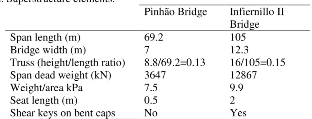
In spite of the major span length of the Infiernillo Bridge (51%), its height/span ratio is only 15% greater than the Pinhão Bridge ratio. This difference reflects not only the increase on the material strength but also the knowledge and confidence on the design, analysis and construction methods available at the time of each bridge construction (see Table 2).
3 4 5 6 7 8 9 10 11 12 13 14 15 16 17 18 19 20 21 22 23 24 25 26 27 28 29 30 31 32 33 34 35 36 37 38 39 40 41 42 43 44 45 46 47 48 49 50 51 52 53 54 55 56 57 58 59 60
For Peer Review Only
Table 2. Superstructure elements.
Pinhão Bridge Infiernillo II Bridge
Span length (m) 69.2 105
Bridge width (m) 7 12.3
Truss (height/length ratio) 8.8/69.2=0.13 16/105=0.15 Span dead weight (kN) 3647 12867
Weight/area kPa 7.5 9.9
Seat length (m) 0.5 2
Shear keys on bent caps No Yes
Even though the substructure height of the Infiernillo II Bridge and the high seismicity of the site where the bridge is located, the pier slenderness ratio and the pier dimension/span ratio of the Infiernillo II are minor than those ratios for the Pinhão Bridge.
Table 3. Substructure elements.
Pinhão Bridge Infiernillo II Bridge Bearing type Pin and roller bearings (see
Figure 5)
Sliding multirotational bearings (see Figure 10) Pier geometry (m)
Cylinder geometry (m)
--
Rectangular pier height (m) 17.0 20.0
Circular pier height (m) -- 25.43-50.13
Total substructure
height(m) 17.0 45.43-70.13
Slenderness ratio (H/r) 24.54 30.73
Pier width/span length 3/69.2=0.043 3.5/105=0.033 Pier depth/span length 6/69.2=0.087 8.5/105=0.081
Foundation Type Stone masonry foundation; rock Reinforced concrete piles Soil type (foundation level) Bedrock Bedrock
As it was typical, for a bridge located in a low seismicity area, constructed 100 years ago, no transverse restrainers (shear keys) were used neither a minimum seat length dimension were considered.
3 4 5 6 7 8 9 10 11 12 13 14 15 16 17 18 19 20 21 22 23 24 25 26 27 28 29 30 31 32 33 34 35 36 37 38 39 40 41 42 43 44 45 46 47 48 49 50 51 52 53 54 55 56 57 58 59 60
For Peer Review Only
3. Structural models
3D structural models of the two bridges were developed using the structural analysis software SAP 2000 (2006). A structural model representative of one span was developed considering the geometrical characteristics of each bridge. Because of the great stiffness of the Pinhão Bridge´s piers the superstructure was considered supported on bearings fixed at their base (see Figure 11-a). On the other side, the great flexibility of the pier-isolation subsystem of the Infiernillo Bridge is of significant importance on its structural response and therefore the numerical model considered is the one represented in Figure 11-b (Jara et al. 2008 b). The Infiernillo Bridge numerical model was calibrated based on ambient vibration measurements, as it is explained in Jara et al. (2008 a).
a) b) Figure 11. Structural models: a) Pinhão Bridge; b) Infiernillo II Bridge.
4. Comparative numerical analysis
A comparative analysis was performed to evaluate the structural behavior and the seismic performance of the Pinhão and the Infiernillo II bridges. The bridge models were analyzed for vertical and seismic loads. The seismic actions considered in these analyses are in accordance with the Portuguese standard (RSA 1983) and the Mexican code edited by the Comisión Federal de Electricidad (CFE 1993).
Natural frequencies, mode shapes, maximum stresses in the structural elements and maximum deflection, were determined for both bridges.
3 4 5 6 7 8 9 10 11 12 13 14 15 16 17 18 19 20 21 22 23 24 25 26 27 28 29 30 31 32 33 34 35 36 37 38 39 40 41 42 43 44 45 46 47 48 49 50 51 52 53 54 55 56 57 58 59 60
For Peer Review Only
4.1 Dead load analysis
4.1.1 Maximum stresses in the structural elements and maximum deflection
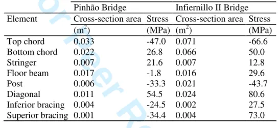
Table 4 presents the maximum stresses in the structural elements of the Pinhão and the Infiernillo II bridges, computed considering only the self-weight of the structures. The elements of the superstructure with higher stress level for both bridges are the diagonals in tension and top chords in compression.
Table 4. Maximum stresses in the structural elements.
Pinhão Bridge Infiernillo II Bridge Element Cross-section area Stress Cross-section area Stress
(m2) (MPa) (m2) (MPa) Top chord 0.033 -47.0 0.071 -66.6 Bottom chord 0.022 26.8 0.066 50.0 Stringer 0.007 21.6 0.007 12.8 Floor beam 0.017 -1.8 0.016 29.6 Post 0.006 -33.3 0.021 -43.7 Diagonal 0.011 54.5 0.024 80.6 Inferior bracing 0.004 -24.5 0.002 27.5 Superior bracing 0.001 -34.4 0.004 73.0
As shown in Table 5, the maximum stress in the principal structural elements due to dead load, is about 32% of the yielding strength for the Pinhão Bridge and 31% for the bridge Infiernillo II, that is, dead load effect is practically the same for both structures.
The maximum vertical mid-span deflection estimated for dead load is 36 mm for the Pinhão Bridge and 81 mm for the Infiernillo II Bridge. This conducts to a deflection/span ratio for the Infiernillo II Bridge 2.4 times greater than the same ratio for the Pinhão Bridge.
Table 5. Global response parameters for the dead load.
Pinhão Bridge Infiernillo II Bridge Maximum stress on superstructure 0.32 fy 0.31 fy
Maximum vertical reaction on bearings (MN) 0.9 3.2 Deflection / span ratio 0.0005 0.0012 3 4 5 6 7 8 9 10 11 12 13 14 15 16 17 18 19 20 21 22 23 24 25 26 27 28 29 30 31 32 33 34 35 36 37 38 39 40 41 42 43 44 45 46 47 48 49 50 51 52 53 54 55 56 57 58 59 60
For Peer Review Only
4.2 Seismic analysis
With the aim of evaluating and comparing the seismic performance of the Pinhão and the Infiernillo II bridges, the structural models of both bridges were subjected to various levels of seismic loading. A modal spectral analysis was developed according to the design spectra presented by RSA and CFE codes.
4.2.1 Natural frequencies
The initial analyses were performed considering the superstructure supported on the bearings fixed at the base, without piers. This idealization is justified because of the extremely high stiffness of the substructure of the Pinhão Bridge.
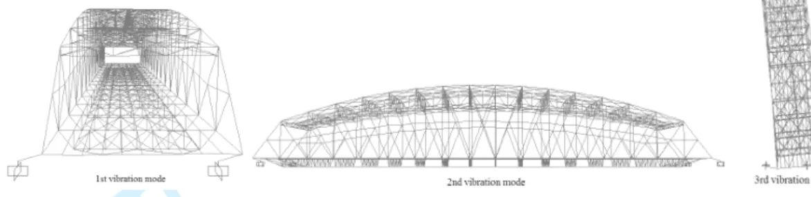
Table 6 presents the first three natural frequencies and mode shapes of the Pinhão and Infiernillo II bridges, computed considering only the self-weight of the structures. The corresponding vibration modes are presented in Figures 12 and 13. As it can be seen in Figure 13, the superstructure of the Infiernillo Bridge moves as a rigid body supported on the isolators. If the piers flexibility was incorporated to the model, the third mode would correspond to transversal displacement of piers with a frequency of 0.68 Hz.
Table 6. Natural frequencies and mode shapes.
Pinhão Bridge Infiernillo II Bridge Vibration
mode Freq.
(Hz) Mode
Freq.
(Hz) Mode
1 1.66 Transversal 0.42 Transverse as rigid body 2 2.85 Vertical 0.43 Longitudinal as rigid body 3 3.11 Torsional 0.66 Rotation around a vertical axis
Figure 12. First three vibration modes of the Pinhão Bridge. 3 4 5 6 7 8 9 10 11 12 13 14 15 16 17 18 19 20 21 22 23 24 25 26 27 28 29 30 31 32 33 34 35 36 37 38 39 40 41 42 43 44 45 46 47 48 49 50 51 52 53 54 55 56 57 58 59 60
For Peer Review Only
Figure 13. First three vibration modes of the Infiernillo II Bridge.
As expected, the frequencies obtained for the Pinhão Bridge are always higher than the frequencies of the Infiernillo II Bridge. This is due to the differences between the span length, height/span ratio and mostly because of the flexibility of the pier-isolators subsystem. For the Infiernillo II Bridge, the mode shapes are governed by the base isolators flexibility.
4.2.2 Seismic zone location of the bridges
The Portuguese code, RSA, divides the Portuguese territory in four zones of seismicity, zones A, B, C and D. Zone A represents the areas of more significant seismicity and zone D represents the areas of reduced seismic risk. Also, RSA considers three types of soils: type I, type II and type III. In the analysis presented in this paper it is assumed that both bridges are located in zone A, in medium stiffness soil (type II). Additionally, the bridges were subjected to the seismic intensity corresponding to the design spectrum of the CFE (1993), for the highest level of seismicity in Mexico (zone “D”) and soil type II, where the Infiernillo II Bridge is actually located.
4.2.3 Seismic actions
RSA establishes two types of seismic actions, one representing earthquakes of moderate magnitude and small focal distance (seismic action type 1) and the other 3 4 5 6 7 8 9 10 11 12 13 14 15 16 17 18 19 20 21 22 23 24 25 26 27 28 29 30 31 32 33 34 35 36 37 38 39 40 41 42 43 44 45 46 47 48 49 50 51 52 53 54 55 56 57 58 59 60
For Peer Review Only
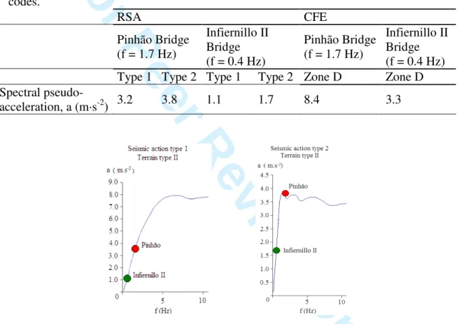
representing earthquakes of higher magnitude and higher focal distance (seismic action type 2). In Figure 14 the design spectra (damping = 2%) for the two action types and the acceleration level for the fundamental vibration mode of the bridges are shown. In Figure 15 the CFE design spectra for a 5% damping coefficient is illustrated. In Table 7, spectral accelerations estimated with both codes and for bth structures are presented, for the corresponding fundamental frequencies.
Table 7. Spectral accelerations for the two bridge structures for the RSA and CFE codes. RSA CFE Pinhão Bridge (f = 1.7 Hz) Infiernillo II Bridge (f = 0.4 Hz) Pinhão Bridge (f = 1.7 Hz) Infiernillo II Bridge (f = 0.4 Hz) Type 1 Type 2 Type 1 Type 2 Zone D Zone D Spectral
pseudo-acceleration, a (m·s-2) 3.2 3.8 1.1 1.7 8.4 3.3
Figure 14. Earthquake demand spectrum (RSA 1983): a) seismic action type 1; b) type 2.
Figure 15. Earthquake demand spectrum (CFE 1993). 3 4 5 6 7 8 9 10 11 12 13 14 15 16 17 18 19 20 21 22 23 24 25 26 27 28 29 30 31 32 33 34 35 36 37 38 39 40 41 42 43 44 45 46 47 48 49 50 51 52 53 54 55 56 57 58 59 60
For Peer Review Only
The Pinhão Bridge is exposed to greater accelerations for the three seismic spectra considered as a consequence of its great stiffness. The first mode accelerations for the Infiernillo Bridge are 34%, 45 % and 39% of the accelerations for the Pinhão Bridge, respectively.
4.2.4 Analysis results
Table 8 presents the maximum stresses in the structural elements of the Pinhão and the Infiernillo II bridges obtained when the bridges are subjected to the design spectrum of the CFE code and the RSA code (seismic action type II). In both bridges, the most stressed elements of the superstructure are the bottom chord and diagonal elements.
Table 8. Maximum stresses in truss elements due to seismic action and dead load. Pinhão Bridge Infiernillo II Bridge
Element RSA long RSA trans CFE long CFE trans RSA long RSA trans CFE long CFE trans (MPa) (MPa) (MPa) (MPa) (MPa) (MPa) (MPa) (MPa) Top chord -53.2 -59.1 -59.0 -72.0 -67.5 -69.5 -69.3 -75.0 Bottom chord 35.3 52.0 45.9 112.9 58.1 66.5 85.2 97.1
Post -39.9 -46.2 -46.0 -61.1 -83.9 -49.4 -51.8 -60.4 Diagonal 52.2 59.1 59.0 73.5 46.4 90.1 90.4 108.0
The maximum stress due to seismic and dead loads combination is about 65% and 42% of the yield stress for the Pinhão and the Infiernillo II bridges respectively. The maximum stresses produced only by seismic actions are 0.5 fy and 0.18 fy for the Pinhão and the Infiernillo II bridges, respectively.
The transversal deflection obtained at the mid-spam section is 16 mm for the Infiernillo Bridge and 18 mm for the Pinhão Bridge. The transversal displacement/span ratio obtained for each bridge is function of the seismic loading intensity, therefore it is justified the larger value obtained for the Pinhão Bridge. Table 9 shows the forces on piers, reactions and displacement of the superstructure for dead plus seismic load combination.
3 4 5 6 7 8 9 10 11 12 13 14 15 16 17 18 19 20 21 22 23 24 25 26 27 28 29 30 31 32 33 34 35 36 37 38 39 40 41 42 43 44 45 46 47 48 49 50 51 52 53 54 55 56 57 58 59 60
For Peer Review Only
Table 9. Analysis results (Seismic load plus self weight condition).
Pinhão Bridge Infiernillo II Bridge
RSA CFE RSA CFE
Reaction on piers (kN)
Longitudinal shear on piers (kN) Transverse shear on piers (kN)
1167 376 1200 1461 842 2724 4469 570 1754 4464 1720 1761 Longitudinal displacement (cm) 0.82 0.97 11.2 38.8 Transverse disp. / span 0.0003 0.0007 0.0012 0.0039 Transverse relative disp. / span 0.0003 0.0007 0.0002 0.0005
5. Global response of the Pinhão Bridge supported on base isolators
A numerical analysis was performed aimed at evaluating the influence of the type of bearings in the dynamic behavior of the Pinhão Bridge. An improvement of the bridge response is expected if bearings isolators of the type used in the Infiernillo II Bridge are incorporated. The period increase would result in a reduced acceleration demand as it can be observed in Figure 13. The isolator’s properties are selected in such way that the fundamental period of the bridge is increased three times, from 0.6 to 1.8 sec. To drive the period of the bridge to 1.8 sec., the lateral stiffness of the supports considered as the equivalent stiffness associated to the maximum expected displacement of the isolator should be 2511 kN/mm. The supports were modelled in SAP 2000 as link elements with bilinear behaviour.
The model was subjected to seismic loading (type II), computed according to the RSA design spectra, with the following characteristics: zone A, soil type II, 2% damping coefficient, and to the CFE design spectra for zone D and the same type of soil.
The dynamic behavior of the Pinhão Bridge, with and without base isolators, is commented in the next paragraphs.
5.1 Natural frequencies
Table 10 presents the first three vibration modes of the isolated Pinhão superstructure. The fundamental frequency of the bridge was reduced from 1.66 Hz for the non isolated structure to 0.94 Hz for the isolated structure. This period shift reduces the 3 4 5 6 7 8 9 10 11 12 13 14 15 16 17 18 19 20 21 22 23 24 25 26 27 28 29 30 31 32 33 34 35 36 37 38 39 40 41 42 43 44 45 46 47 48 49 50 51 52 53 54 55 56 57 58 59 60
For Peer Review Only
spectral acceleration from 3.8 m/s2 to 2.0 m/s2 in the case of the RSA spectra and from 8.4 m/s2 to 5.8 m/s2 in the CFE spectra.
Table 10. Numerical natural frequencies and corresponding vibration modes of the Pinhão Bridge supported on base isolators.
Vibrati on mode
Freq.
(Hz) Mode
1 0.94 Transverse displacement as rigid body 2 1.01 Longitudinal displacement as rigid body 3 1.70 Rotation around a vertical axis
5.2 Analysis results
The flexibility of the isolation system modifies the mode shapes of the non isolated model. The vibration modes are now similar to those of the Infiernillo II previously commented. Unlike the dynamic properties of the non isolated model, the frequencies values of the first and second mode (corresponding to transverse and longitudinal directions) are quite similar for the isolated bridge mainly due to the same stiffness of the isolation system in both directions.
Table 11 shows the maximum stress values in the structural elements for the Pinhão Bridge supported on base isolators when it is subjected to the seismic action defined by the response spectra. It is notorious that the stresses due to seismic actions are smaller than the stresses caused by dead load (Table 4).
Table 11. Maximum stress (MPa) in the structural elements of the Pinhão Bridge considering the use of base isolators.
Pinhão Bridge
Element RSA long RSA trans CFE long CFE trans Top chord -45.5 -46.6 -46.7 -50.8 Bottom chord 14.7 19.1 19.4 34.4 Post -36.4 -36.9 -40.6 -42.4 Diagonal 57.9 59.2 61.5 66.0
Regarding to the maximum stress in the structural elements, the use of base isolators produces the stress ratios presented in Table 12. In general, the use of base 3 4 5 6 7 8 9 10 11 12 13 14 15 16 17 18 19 20 21 22 23 24 25 26 27 28 29 30 31 32 33 34 35 36 37 38 39 40 41 42 43 44 45 46 47 48 49 50 51 52 53 54 55 56 57 58 59 60
For Peer Review Only
isolators led to a reduction of the maximum stresses. The structural elements most sensible to the change of bearings conditions are the bottom chords. This is probably due to the higher restriction of the bridge’s displacements imposed by the original bearings. When the Pinhão Bridge is isolated a stress reduction up to 43% was obtained. The stress decrease is greater in transverse direction while in longitudinal direction the maximum reduction is 24%. The CFE/RSA spectral acceleration ratio corresponding to the non isolated bridge is 1.32, while this ratio is reduced to 1.15 for the isolated bridge, showing the minor influence of the seismic action when the isolators are incorporated to the bridge.
Table 12. Ratio of maximum stress without and with isolators. Pinhão Bridge
Element RSA long RSA trans CFE long CFE trans Top chord 1.24 1.15 1.24 1.43 Bottom chord 2.40 2.72 2.37 3.28 Post 1.24 1.08 1.13 1.42 Diagonal 1.19 1.09 1.12 1.35
Table 13 shows the forces on piers, reactions and displacement of the isolated superstructure for the dead plus seismic load combination. It is also shown the response ratio of the original structure versus the isolated one. Remarkable is the large ratio obtained for longitudinal shear on piers mainly due to the longitudinal movement restriction of bearings in the original model. It is also important to note that the transverse relative displacement/span ratios of the Pinhão are quite similar to those obtained in the Isolated Infiernillo II model despite of the differences in length of both bridges.
Table 13. Isolated Pinhão model (Seismic load plus self-weight condition)
Pinhão Bridge Original/isolated ratio
RSA CFE RSA CFE
Reaction on piers (kN)
Longitudinal shear on piers (kN) Transverse shear on piers (kN)
1940 238 224 2218 774 748 1.23 12.66 3.96 1.34 7.91 1.98 3 4 5 6 7 8 9 10 11 12 13 14 15 16 17 18 19 20 21 22 23 24 25 26 27 28 29 30 31 32 33 34 35 36 37 38 39 40 41 42 43 44 45 46 47 48 49 50 51 52 53 54 55 56 57 58 59 60
For Peer Review Only
Longitudinal displacement (cm) 4.91 15.68 0.22 0.08 Transverse disp. / span 0.0007 0.0007 0.43 1.00 Transverse relative disp. / span 0.0001 0.00004 3 17.5
6. Conclusions
Two bridges built in different periods with similar geometrical characteristics and almost the same stress level under dead loads, are analyzed from the point of view of their seismic response. The following conclusions can be drawn:
• In spite of the major span length and width of the Infiernillo Bridge, the height/span ratio is 46% of the Pinhão bridge ratio. This difference reveals not only the increase on the material strength but also the confidence on the design, analysis and construction methods available at the time the bridges were constructed.
• The same conclusion can be drawn regarding to the pier slenderness ratio and the pier dimension/span ratio, even though the taller piers of the Infiernillo II Bridge and the high seismicity of the site where the Infiernillo II Bridge is located. As it was usual, for a bridge located in a low seismicity area constructed 100 years ago, no transverse restrainers (shear keys) were used neither a minimum seat length dimension were considered.
• The frequencies of the Pinhão Bridge are always higher than the frequencies of the Infiernillo II Bridge as a result of the differences between the span length, height/span ratio and mostly because of the flexibility of the pier-isolators subsystem.
• Seismic stress demands in the Pinhão are larger than those of the Infiernillo II Bridge, for the three spectra considered, exposing the difference in dynamic properties in both bridges. Even though the similar stresses in both bridges caused by dead load, the maximum stresses produced by seismic actions are more than 2.7 times for the Pinhão Bridge.
• An important stress reduction is obtained when the Pinhão Bridge is isolated. The stress decrease is greater in transverse direction. The CFE/RSA spectral acceleration ratio corresponding to the non isolated Pinhão Bridge is 1.32, while this ratio is reduced to 1.15 for the isolated bridge, showing the minor influence of the seismic action when the isolators are incorporated to the bridge.
Acknowledgements
The authors would like to acknowledge the GEG – Gabinete de Estruturas e Geotecnia (Portugal) for the data related to the Pinhão Bridge assessment, geometry and materials characterization results.
References
Astaneh-Asl, H., Bolt, B., Mc Mullin, K. and Cho, S., 1994. Seismic Performance of Steel Bridges During the Northridge Earthquake. Department of Civil Engineering College of University of California at Berkeley, UCB/CE-Steel-94/0.
CFE, 1993. Manual de Diseño de Obras Civiles de la Comisión Federal de
Electricidad, Diseño por Sismo. Instituto de Investigaciones Eléctricas de la CFE (in Spanish).
3 4 5 6 7 8 9 10 11 12 13 14 15 16 17 18 19 20 21 22 23 24 25 26 27 28 29 30 31 32 33 34 35 36 37 38 39 40 41 42 43 44 45 46 47 48 49 50 51 52 53 54 55 56 57 58 59 60
For Peer Review Only
Eshghi, S. and Ahari, M. N., 2005. Performance of transportation systems in the 2003 Bam, Iran, Earthquake. Earthquake Spectra, Vol. 21, No. S1, pp. S455-S468. Faria, R. G., 2008, Procedimentos com vista à monitorização de estruturas – Teste do
sonar e ensaio da Ponte do Pinhão. Master Thesis. Faculty of Engineering, University of Porto, Porto, Portugal (in Portuguese).
Hashimoto, S., Fujino, Y. and Abe, M., 2005. Damage analysis of Hanshin Expressway Viaducts during 1995 Kobe Earthquake. II: Damage mode of single reinforced concrete piers. Journal of Bridge Engineering, Vol. 10, No. 1, pp. 54-60.
Hsu, Y. T. and Fu, C. C., 2004. Seismic effect on highway bridges in Chi Chi
earthquake. Journal of Performance of Constructed Facilities, Vol. 18, No. 1, pp. 47-53.
Jara, J. M., Jara, M. and Hernández, H.,2008. Expected behavior of the Infiernillo II Bridge in Mexico. Sixth National Conference on Bridges and Highways, Charleston, South Caroline, USA, paper ID No. 3A1-3.
Jara, J. M., Galván, A., Aguilar, I., Jara, M. and Hernández, H., 2008. Seismic vulnerability of an isolated bridge in Mexico. 14th World Conference on Earthquake Engineering, Beijing, China, paper ID No. 05-02-0109. Jara M., Álvarez J. J. and Jara J. M., 2006. Algunas deficiencias de puentes
sísmicamente vulnerables. Memorias del XV Congreso Nacional de Ingeniería Estructural, Puerto Vallarta, Jalisco, 2006 (in Spanish).
Kawashima, K., 2002. Damage of bridges resulting from fault rupture in the 1999 Kocaeli and Duzce, Turkey earthquakes and the 1999 Chi-Chi, Taiwan esrthquake. Structural Engineering/Earthquake Engineering, JSCE, Vol. 19, No.2 [Special Issue], pp. 179s-197s.
Martins, M., Torres, M. and Freire, P., 1998. Pontes Rodoviárias Metálicas. Junta Autónoma de Estradas, Portugal, ISBN 972-8498-03-9 (in Portuguese). Moehle, J. P. and Eberhard, M. O., 2003. Earthquake damage to bridges. Bridge
Engineering. Seismic Design, W.-F.Chen and L. Duan (eds.), CRC Press, pp. 2-1 2-33.
Pinto, J., Santos, N. and Fonseca, R., 2005. Ponte metálica do Pinhão – Inspecção e Elaboração do Estudo de Reabilitação da Obra de Arte. Porto, Portugal (in Portuguese).
RSA (2003), Regulamento de Segurança e Acções para Estruturas de Edifícios e Pontes, Decreto-Lei nº 235/83, de 31 de Maio. Porto, Portugal: Porto Editora (in Portuguese).
SAP2000, 2006. Linear and nonlinear static and dynamic analysis and design of three-dimensional structures, Version 11, Computer and Structures, Inc. Uang, C., Elgmanal, A., Li, W. and Chou, C., 1999. Ji-Ji, Taiwan Earthquake of
September 21, 1999”: a brief reconnaissance report. Department of Structural Engineering, University of California, San Diego, URL:
http://www.structures.ucsd.edu/taiwaneq/taiwan1.htm 3 4 5 6 7 8 9 10 11 12 13 14 15 16 17 18 19 20 21 22 23 24 25 26 27 28 29 30 31 32 33 34 35 36 37 38 39 40 41 42 43 44 45 46 47 48 49 50 51 52 53 54 55 56 57 58 59 60