STABILITY AND CONTROL OF HYBRID AIRSHIPS:
A NEW CONCEPT
Diego Núñez González
Dissertação para a obtenção de Grau em Mestre em
Engenharia Aeronáutica
(Ciclo de estudos integrado)
Orientador: Prof. Doutor Jorge Miguel dos Reis Silva
Co-Orientador: Prof. Doutor Pedro Vieira Gamboa
iii
AVISO
A presente dissertação foi realizada no âmbito de um projeto de investigação
desenvolvido em colaboração entre o Instituto Superior Técnico e a
Universidade da Beira Interior e designado genericamente por URBLOG -
Dirigível para Logística Urbana. Este projeto produziu novos conceitos
aplicáveis a dirigíveis, os quais foram submetidos a processo de proteção de
invenção através de um pedido de registo de patente. A equipa de inventores é
constituída pelos seguintes elementos:
Rosário Macário, Instituto Superior Técnico;
Vasco Reis, Instituto Superior Técnico;
Jorge Silva, Universidade da Beira Interior;
Pedro Gamboa, Universidade da Beira Interior;
João Neves, Universidade da Beira Interior.
As partes da presente dissertação relevantes para efeitos do processo de
proteção de invenção estão devidamente assinaladas através de chamadas de
pé de página. As demais partes são da autoria do candidato, as quais foram
discutidas e trabalhadas com os orientadores e o grupo de investigadores e
inventores supracitados. Assim, o candidato não poderá posteriormente
reclamar individualmente a autoria de qualquer das partes.
Covilhã e UBI, 8 de Junho de 2015
_______________________________
(Diego Núñez González)
v
Dedicatory
I want to dedicate this work to my family and many friends. A special feeling of gratitude to my loving parents, Enrique and Amparo, whose words of encouragement and support made me believe in me every day. To my sister Vane and my little nephew Víctor, this is for you too.
I also dedicate this work to my friend Ángel, for his support over all these years, and each and every one of my friends.
vii
“Lo importante no es llegar, sino el camino en sí”.ix
Acknowledgments
This paper could not be written to its fullest without Professor Jorge Miguel Reis Silva, who served as my supervisor, as well as one who challenged and encouraged me throughout my time spent studying under him. He would have never accepted anything less than my best efforts, and for that, I thank him.
To Professor Pedro Vieira Gamboa, who were my co-supervisor for all the support and dedication in this work. Also to João Neves, since this thesis would not have been possible without him.
To my family, friends and colleagues for their support throughout all these years.
To Professor Rosário Macário and Professor Vasco Reis from Instituto Superior Técnico, for their time and participation.
Finally, my special thanks to Sara Claro, Tiago Santos and Maria Baltazar. Without their continued efforts and support, I would have not been able to bring my work to a successful completion.
x
xi
Abstract
Nowadays, airships are generating a growing interest. The development of new technologies has allowed hybrid airships to become a reality, leading to a significant number of new research projects. In this way, numerous lines of research are opened in all areas of airship designs and, especially, this will allow the development of stability and control systems that are truly efficient.
To overcome this limitation in the stability and control there are numerous possible solutions for hybrid airships. This thesis’ objective is to analyze the feasibility and performance of a new concept of stability and control system. This system is a combination of two elements: a distribution of six control surfaces and a set of four variable pitch rotors.
For that, four different prototypes were built. Two of them are a scale model of the airship aimed to test the stability and control of all surfaces. The third one is a quad rotor to analyze the behavior of a variable pitch solution. Finally, the last prototype is a scale model again, but this time aimed to test the performance of a quad rotor airship with fixed pitch control. The results from the different tests showed this concept is a promising way to stabilize and control a hybrid airship. Tests of the first prototype validated a new mode of control which solves different problems related to the stability and control. The results from the tests of prototype 1.5 confirmed that a six surfaces configuration allows full control for different types of performance, being necessary to continue investigating this concept as well as its implementation along with a system of rotors. Prototype 2 results showed that a variable pitch rotor solution for a quad rotor provides an effective and feasible control, among other advantages. The results from prototype 2.5 showed that because the airship model does not have an internal or external structure, it has vibration problems at high rotor power settings. In addition, the airship was uncontrollable when utilizing a system of fixed pitch rotors, so it is necessary to study the implementation of the variable pitch ones.
Finally, one can conclude that the combination of a system of six control surfaces with a system of four rotors with variable pitch is a promising way to stabilize and control a hybrid airship.
xiii
Resumo
Hoje em dia, os dirigíveis estão gerando um crescente interesse. O desenvolvimento de novas tecnologias tem permitido aos dirigíveis híbridos tornar-se uma realidade, multiplicando o número de investigações sobre eles. Desta forma, inúmeras linhas de investigação são abertas em todas as áreas de desenho dos dirigíveis e, especialmente, isso permitirá que o desenvolvimento de sistemas de controlo e de estabilidade que são verdadeiramente eficientes.
Para superar essa limitação na estabilidade e no controlo existem numerosas soluções possíveis para os dirigíveis híbridos. O objetivo desta tese é analisar a viabilidade e o desempenho dum novo conceito de sistema de estabilidade e controlo. Este sistema é uma combinação de dois elementos: uma distribuição de seis superfícies de controlo e um conjunto de quatro rotores de passo variável.
Para isso, foram construídos quatro protótipos diferentes. Dois deles são um modelo em escala do dirigível com o objetivo de testar a estabilidade e controlo de todas as superfícies. O terceiro é um quad rotor para analisar o comportamento de uma solução de passo variável. Finalmente, o último protótipo é novamente um modelo em escala, mas desta vez tem como objetivo testar o desempenho de um dirigível quad-rotor com controlo de passo fixo.
Os resultados dos diferentes ensaios mostram que este conceito é um caminho promissor para estabilizar e controlar um dirigível híbrido. Os testes do primeiro protótipo validaram um novo modo de controlo que resolve diversos problemas relacionados com a estabilidade e o controlo. Os resultados dos ensaios do segundo protótipo confirmaram que uma configuração de seis superfícies de controlo permite um controlo total para diferentes atuações, sendo necessário continuar a investigação deste conceito e a sua implementação em conjunto com um sistema de rotores. Os resultados do protótipo 2 mostraram que uma solução de passo variável proporcionará um controlo eficiente e fiável para um quad rotor, entre outras vantagens. Os resultados do protótipo 2.5 mostraram que ao não ter uma estrutura interna ou externa, o dirigível têm problemas de vibrações para grandes potências nos rotores. Além disso, o dirigível foi incontrolável quando se utilizou um sistema de rotores de passo fixo, por isso é necessário estudar a implementação de passo um sistema de passo variável.
Finalmente, pode-se concluir que a combinação de um sistema de seis superfícies de controlo com um sistema de quatro rotores com passo variável é um caminho promissor para estabilizar e controlar um dirigível híbrido.
Palavras-chave: Dirigível Híbrido, Sistema de Estabilidade e Controlo, Sistema de Superfícies,
Passo variável
xv
Table of Contents
Dedicatory ………v Acknowledgements………ix Abstract ………xi Resumo………xiii Table of Contents………xv List of Figures………xviiList of Tables ………xix
1. Introduction………1
1.1. Motivation………1
1.2. Object and Objectives………2
1.3. Dissertation Structure ………2
2. State of Art ………3
2.1. Introduction ……… 3
2.2. Stability and control surfaces configuration………3
2.3. Variable pitch multi-rotor system……… 11
2.4. Conclusions ………18 3. Case of Study ………19 3.1. Introduction………19 3.2. Prototype 1 ………20 3.3. Prototype 1.5 ………30 3.4. Prototype 2 ………32 3.5. Prototype 2.5 ………34 3.6. Conclusions ………35 4. Results ………36 4.1. Introduction………36 4.2. Prototype 1 ………36 4.3. Prototype1.5 ………44 4.4. Prototype 2 ………47 4.5. Prototype 2.5………48 4.6. Conclusions ………50 5. Conclusions………52 5.1 Dissertation Synthesis ………52 5.2 Final Conclusions………53 5.2 Future Work………54 References………55
xvii
List of Figures
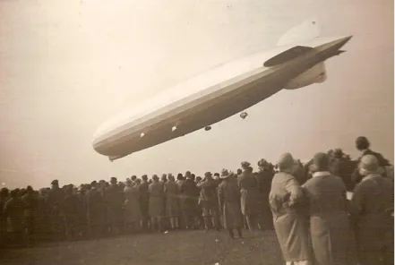
Figure 1: LZ 127 Graf Zeppelin cross tail ………5
Figure 2: Standard reference axis for aircraft, including airships ………6
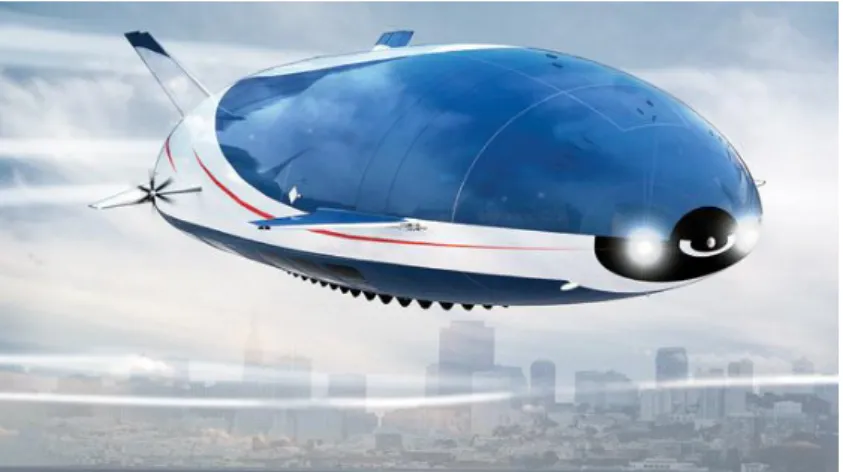
Figure 3: A conceptual hybrid airship designed by Aeros Aeronautical Systems………11
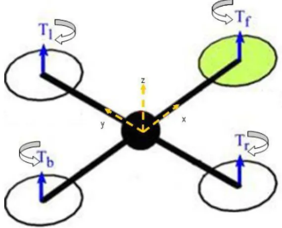
Figure 4: Simplified quad-rotor vehicle in a stable hove……… 13
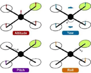
Figure 5: Quad rotor dynamics ………14
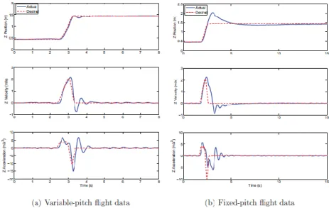
Figure 6: Flight data for the variable-pitch versus fixed-pitch flying the same trajectory ……15
Figure 7: Vertical tracking error ………16
Figure 8: Roll tracking error ……… 17
Figure 9: Simple conceptual scheme of the airship ………19
Figure 10: Motor support built in carbon fiber composite ………22
Figure 11: Prototype 1 assembled without motor support ………23
Figure 12: Positioning surfaces scheme ………26
Figure 13: New control Surface structure ………30
Figure 14: Control surfaces support ………31
Figure 15: Final assembly of prototype 1.5 ………32
Figure 16: Motor together with the mechanism used for variable pitch ………33
Figure 17: Quad-rotor simplified without wires and electronic components ………34
Figure 18: Prototype 2.5 assembled ………35
Figure 19: Pitch angle created during takeoff maneuvers for flight mode 1………40
Figure 20: Airship during the last tests for flight mode 3………46
Figure 21: Structure utilized for testing the prototype 2………47
xix
List of Tables
Table 1: Mass of components ………24
Table 2: Lift and max weight estimation ………25
Table 3: Center of mass position for maximum weight ………25
Table 4: Center of mass position for motorless configuration ………26
1
1. Introduction
1.1.
Motivation
Despite airships have been used for many years [1], their implementation has not been as strong as one might expect and their uses are mainly limited to surveillance, leisure and advertisement.
Even so, right now there is a growing interest regarding their use into new areas due to the implementation of new technologies. Thus, the utilization of composite materials, vectoring motors or computer assisted design among others represent a significant advance pathway. The unification of these developments leads to a new type of airship, the Hybrid Airship. This type of airship combines the use of older technologies with new technologies, thereby, the lift will be obtained by combining the utilization of helium with aerodynamic lift, or, the control will be achieved by a combination of stabilizing surfaces and a multirotor system. For years, the main problem of airships has been to obtain a stability and control system that worked in a quasi-autonomous and efficient way. Because they are large aircraft, control in urban environments or in cruise flight is a fundamental pillar to its implementation. Therefore, the fact of obtaining a system that allows a stable and precise control in all kinds of activities, both cruising and maneuvering, will be the main objective of this thesis.
A hybrid system of control surfaces with a system of rotors (quad-rotor) will be a new research line that will be studied both individually and collectively [2].
A control surfaces system in conjunction with the main motor will provide the necessary dynamic lift in cruise flight to ensure optimum control of the attitude of the airship and also to contribute to the dynamic stability. With this system, cruise flight turns similar to a conventional aircraft cruise flight, thereby facilitating the flying.
Furthermore, the four rotors system (quad-rotor) will allow vertical lift for take-off / landing and in stationary flight maneuvers, as well as a stability control form through the use of a variable pitch system in contrast to standard fixed-pitch. Fixed-pitch multi-rotor designs are mechanically simple since they are completely controllable without the complexity of the control linkages and swashplate that are inherent in traditional pod-and-boom style helicopters, but this has significant limitations in the performance of the rotors such as limitations to generate thrust in more than one direction or limitations caused by the inertia of the motor and propellers.
In this way, the implementation of a stability and control system and a variable pitch quad-rotor into an UAV (Unmanned Aerial Vehicles) will allow to get reliable results in order to its
2
implementation in a system of large rotors for a hybrid airship, avoiding limitations of a standard control system.
1.2.
Object and Objectives
The main objective of this thesis is the development and testing of a hybrid stability and control system for a hybrid airship, so that the operational requirements such as take-off / landing, stationary flight and cruise flight are satisfied. This system consists of a group of six control surfaces and a set of four variable pitch rotors. To do this, it was divided into two main parts, one dedicated to the control surfaces system and another concerning the rotor system.
Four scale prototypes were built and they allowed to simulate the performances of the airship. Thus, the first two prototypes were designed to study in depth the performance and control of the airship in different maneuvers through the utilization of the control surfaces system with real flight tests. Thus, it was possible to check the longitudinal, lateral and directional stability and control of the airship for take-offs, landing or cruise flight. Also, another main objective is the creation and later validation of different flight modes that satisfy the operational requirements.
On the other hand, the other two prototypes allowed to test the performance of a quad-rotor relative to the stability and control. This way, prototype 2 main objective is to check the performance of a variable pitch quad rotor in order its implementation in the airship. On the other hand, prototype 2.5 was built to test the performance of the airship with a fixed pitch rotor system.
1.3.
Dissertation Structure
The development of this thesis begins as part of the multidisciplinary project of an airship. Thus, it is divided into five chapters.
In the first chapter the introduction of this work is presented, including the motivation, the main object and objectives and the structure of the thesis.
The second chapter corresponds to the state of the art and it contains a historical review of the different types of control and stability in airships as well as the latest advances.
In the third chapter the development of the work is detailed, including the construction of prototype 1, prototype 1.5, prototype 2 and prototype 2.5, as well as the case of study. The fourth chapter presents a detailed explanation and discussion of the results obtained in the various tests.
Finally, the fifth chapter includes the conclusions and the future work that would be needed to continue the project.
3
2. State of Art
2.1.
Introduction
Nowadays, creating a system of stability and control has become the main objective of development in the airship design and, specifically, in the case of hybrids Airships. The utilization of new technologies opens new lines of research for overcome the obstacle that represents the creation of a stability and control system to be effective in any operating condition.
The first airships, non-rigid, could only be controlled using control surfaces with limited dimensions and performance, since the blimp could not support heavy loads by not having an internal structure. Another problem was the impossibility of having vertical thrust, so a small runaway was needed to take off and land with the help of ten to twenty operators.
In the case of hybrid Airships, as they have an effective internal structure, allow to solve the above problems getting greater maneuverability to comply with operational requirements. Therefore, the combination of different elements such as gas lift, the multirotor system and control surfaces is presented as a promising solution.
2.2.
Stability and control surfaces configuration
The first airships had a limited system stability and control and, going back to the second half of the nineteenth century we can find the first attempts of balloons that do not depend on wind currents to navigate in the desired direction. The airship Dupuy de Lome [3] was one of the first airships developed in 1872 by the engineer who gives it its name; this aircraft had a wingspan of 36 m and a 1.5 kW power engine with a speed reaching between 9 and 11 km/h. Thus, the control was performed through the engine and a rudimentary system of wires driven by several operators. In the following years, the first electric-powered airships were already made in different countries, leading to a huge increase in its popularity.
In the early twentieth century, it was probably in Spain where there were the greatest advances. On the one hand, Manuel Rivera and Sempere presented an airship which had a similar profile than aircraft and a metal internal structure, being this a very important step towards opening new lines of research and application of airships, as well as a first approximation of use of wings for aerodynamic lift in cruise flight [4]. On the other hand, Leonardo Torres Quevedo designed a new type of airship with a rigid structure, which facilitated a more stable flight and the inclusion of heavier engines. This project would lead eventually to the construction of the airship Astra-Torres, in collaboration with the French company Astra [5]. Thus, we see that these two airships represent a first approach to the concept of hybrid airship.
4
Nowadays, the main use of the airships that are in service is for marketing or monitoring purposes, being still a fairly marginal use. During the last two decades, different companies resumed or initiated research on different types of airships. For example, Zeppelin designed the Zeppelin NT (1997), a semi-rigid airship exclusively filled with helium. Thus, this new concept of airship will be heavier than the air with full load, being able to be lighter-than-air when the payload is low and with a very small amount of fuel. Therefore, the Zeppelin NT has three motors in order to generate the necessary thrust and, moreover, give it greater control and maneuverability. Thus, two motors will be located laterally and they will have propellers with a range of motion of 90° upward and 30° downward, so the horizontal position will be its main direction. The aft motor powers a pushing propeller that can be turned 90° downward, as well as a steering propeller directed to the side and working similarly to the lateral-thrust units of some ships. This control system is complemented by three control surfaces, which are a vertical stabilizer and two horizontal ones with a negative dihedral configuration forming 120° each one of them [6].
Furthermore, the concept called Turtle Airship (2006) results in a good approximation to the concept of "future airship". This airship has solar panels on the top, allowing it to fly autonomously over long distances. Still, its two main innovations have more to do with getting the support and with stability and control. As for the support, Turtle Airship can fly exclusively with aerostatic lift, but in case of wanting increase significantly the payload, the profile of the airship will provide aerodynamic lift in cruise flight and for low-speed maneuvers or take-off/ landing the airship has a system of electric motors, powered by solar panels, which may direct their thrust vertically up or down as needed. As for the stability and control, this airship will have a small size six control surfaces scheme; two vertical stabilizers will be placed in parallel at the top and four horizontal stabilizers distributed in a rectangular way, being a pair ahead and the other behind. This surfaces scheme beside the movable electric motors and the aerodynamic lift of the own airship create a robust stability and control system for maneuvers at low speed or stationary or in cruise flight [7, 8].
The standard configuration of control surfaces, as seen in fig. 1, was for many years a set of four control surfaces that are usually placed in a cross in order to simplify the control [9]. Thus, conventional airships had two rudders (one up and one down) and two lateral stabilizers (one on each side). This arrangement of the control surfaces simplifies the control of the airship because each pair controls a shaft as occurs in many conventional aircraft (aircrafts with T or inverted-T tail), so the vertical pair controls the yaw and horizontal pair controls the pitch. Despite its simplicity and fulfill its objective of changing the attitude of the airship moderately, this configuration is limited when performance requirements, operability, stability and support are greater. For example, the fact that a rudder is placed down is a ground operational limitation due to the ease of being damaged. Another important limitation is the difficulty of controlling the roll by not having flaps, which could be a problem of stability in adverse situations.
5
Fig. 1: LZ 127 Graf Zeppelin cross tail
In a first conclusion it could be said that the stability and control systems were very simple for decades and which represented a major limitation to the performances and usefulness of this type of aircraft. Nowadays, various lines of research seems quite promising through the utilization of more complex control and stability systems that combine different configurations of stabilizing surfaces and propellers. Thus, a detailed analysis of the stability and control is required.
2.2.1.
Stability
When talking about stability is important to differentiate between two fundamental types of stability:
Real static stability should be defined as one which exists when the airship is in constant actuation and this tends to return to its initial position immediately. The requirement for static stability defines requirements on the pitching moment slope (Mα<0) and the yawing moment slope (Nβ>0) for traditional aircraft heavier than air.
For airships, it is a sufficient, but not necessary condition because some airships can be statically stable even when the yawing moment slope is negative [10].
Dynamic stability is defined as the overall tendency of an airplane to return to its original position, following a series of damped out oscillations. In this type of stability the control surfaces still become more important to avoid abrupt transitions.
Thus, for both types of stability it can be said that an airship has positive stability if it develops forces or moments which tend to restore it to its original position, that an airship has neutral stability if the restoring forces are absent and the aircraft will neither return from its disturbed position, nor move further away or that an airship has negative stability if develops forces or moments which tend to move it further away. Negative stability is, in other words, the condition of instability. An airship with both stabilities defined as positive
6
could operate cruise as hands-off, but in many cases, this could severely limit maneuverability.
Furthermore, it is possible to differentiate the type of stability according to the axis or the type of movement of the airship as seen in fig. 2. These three types of stability are lateral stability, longitudinal stability and directional stability.
Fig. 2: Standard reference axis for aircraft, including airships.
Longitudinal stability is the stability that occurs around the lateral axis of the airship, i.e., pitch stability. For conventional aircraft both predominant elements in longitudinal stability are the position of the center of gravity and the horizontal stabilizers. The center of gravity should be located forward of the center of pressure so that the aircraft will behave with a nose-down attitude. In the case of airships, this can make a big difficulty because of different factors that can displace the center of pressure, because it is not only necessary to pay attention to flight conditions and attitude, but rather the behavior of helium inside is an important factor to consider. Thus, this displacement of helium when varying the attitude or because of climate effects (sun in the front, rain ...) have a great effect on the distribution of the center of pressure [11].
Conventional horizontal stabilizers are located in the tail so that when the angle of attack on the wings is increased by a disturbance, the center of pressure moves forward, tending to turn the nose of the airplane up and the tail down. The tail, moving down, meets the air at a greater angle of attack, obtains more lift and tends to restore the balance. In the case of airships the theoretical performance is similar. In a recent study the performance of a conventional configuration for a dirigible tail (cross configuration) is compared against a setting of "inverted Y" resulting in the airship has fewer longitudinal static stability at low speed [12]. Therefore, it would be
7
interesting to maintain a horizontal configuration of stabilizers which work in the horizontal plane the same way as in the configuration in cross.
In the case of airships is vital to have into consideration an additional element in terms of longitudinal stability, critical speed. The critical speed is characterized as the speed at which attitude changes will not result in lift changes, and when crossing this speed, the elevator effect on lift reverses. For this reason some books use the term "reversal speed" for the critical speed.
Starting from the Dr. Munks’ formula is possible to calculate the value of the critical speed for an airship without control surfaces [13]:
𝑀𝑒= 𝑉𝑜𝑙𝑢𝑚𝑒 × 0.5𝜌𝑉2(𝑘2− 𝑘1) sin 2𝜃 (1)
Where k2 and k1 indicate the effect of gas movement inside the airship and θ is the
pitch angle. The critical speed is reached when this resultant airforce equals the moment induced by the weight:
𝑊ℎ sin(𝛼 + 𝜃) = 𝑉𝑜𝑙𝑢𝑚𝑒 × 0.5𝜌𝑉2(𝑘
2− 𝑘1) sin 2𝜃 (2)
Where 𝛼 is the angle of attack. In this sense, the critical speed is the maximum speed at which the gravity moment is able to compensate the moment induced by dynamical lift. This value will be low enough for an airship could operate safely, so introducing stability surfaces critical speed value increases significantly [9]. Tail usual configuration adds a new term to the previous equation, but other configurations would be even more efficient. If the airship is not longitudinally stable, or if in other words, it is being operated above its critical speed, the pilot must correct deviations from the chosen path as soon as they appear, while on a stable airship these deviations would be capable of self-correction if left manually uncorrected.
This critical speed should not be exceeded due to different factors. During flight both the mass and the lift will not stay constant due to atmospheric influences (sun, rain…) or fuel burn. To stay at the desired altitude, the airship can compensate for any imbalance by creating dynamic lift. If the ship is fast enough, a negative deflection of the horizontal tail surface or a shifting of masses backward will increase lift. In the other hand, at low speed, however, aerodynamic lift is much lower, but both mass and static lift are unchanged. Now the airship needs considerably more elevator deflection for the same pitch attitude change. The downforce at the horizontal tail must still be equal to that at high speed, since the static moment has not changed, and the lower dynamic pressure at low speed is compensated by deflecting the elevator by a bigger angle. Obviously, deflection angle is limited by mechanical factors and this can create dangerous situations when speed is really low as, for example, landing. A good way to avoid a crash in this situation is the application of reverse thrust combined with a positive elevator deflection which lifts up the tail.
8
The use of control surfaces at the front with a negative deflection lifts down the nose, so it is another good way too.
Therefore it is necessary to ensure as a project parameter that the airship would be longitudinally stable for both low and high speeds. The configuration of the stabilizing surfaces is a key parameter in order to increase his critical speed and in order to ensure a rapid and efficient response in low-speed maneuvers.
Directional stability is the stability around the vertical or normal axis, i.e., yaw stability. The most important feature for a conventional aircraft that affects directional stability is the vertical tail surface, that is, the fin and rudder. In airships standard configuration is one upper and one lower surface on the vertical axis, although a configuration of two parallel surfaces at the top is also a good solution. When the rudder is set in neutral it acts as an additional fin surface, but the total fin surface isn’t usually large enough to provide complete directional stability. This is quite different from the condition of longitudinal stability where stability surfaces can be locked in any position allowing the airship to return to its initial state when any disturbance occurs. As soon as there is any deviation from the straight line of flight, the air strikes on the side of the airship and sets up a moment tending to turn the airship farther from its original course. This moment corresponds exactly to the previous moment, Me, which opposes longitudinal stability. Thus, the vertical
stabilizers attempt to counteract this moment, but except for small perturbations its effect is insufficient and it should be use the rudder to recover the attitude [9]. Therefore, vertical stabilizers must be configured and dimensioned in order to ensure the directional stability in normal flight conditions. Still, airships tend to be unstable in yaw so it is also needed special attention in the control configuration.
Lateral stability is the stability around the longitudinal axis, or roll stability. Lateral stability is a difficult problem in conventional aircrafts. On the other hand, airships don’t exhibit this problem since the static restoring moment acts with regard to roll. The only rolling motions are those due to side gusts against the airship and those due to centrifugal force when turning, but the moments of these forces are overcome immediately by the large restoring moment due to the position of the center of gravity [14].
Therefore, airships are very stable around the longitudinal axis because of their own configuration.
9
2.2.2.
Control
Generally one can divide the control of an aircraft as directional control and altitude control. In the case of conventional aircraft these two types of control overlap each other and are operated by a single pilot. On the other hand, traditional airships had two pilots working in coordination, one in charge of steering control and the other one in charge of altitude control. This was because of the possibility of varying the static lift of the own airship.
Directional control is the type of control that is responsible for the course of the airship in the horizontal plane. During cruise flight the airship will hold its own course unless acted on by some exterior forces such as gusts. When this happens, it is necessary to operate the rudder in the opposing direction. If air is very gusty is impossible to predict yawing, so the magnitude of the oscillations should be kept low by pilot.
On the other hand, the performance of the rudder or rudders will be quite limited to have an efficient yaw control, since the airships tend to be unstable in yaw. Moreover, its performance involves a complex control process to vary the direction and to correct. For example, when it is desired to turn to the right, the rudder is put over to the right. The instantaneous effect of this rotation is to produce a force to the left acting on the right side of the rudder and this force to the left has a dual effect. In the first place, it gives the moment about the center of gravity tending to turn the nose to the right and, in the second place, it moves the entire airship to the left. Both motions combine to cause the air to strike on the left of the envelope and so to turn the nose still farther to the right. This creates a centripetal force to the right so that the airship starts to move to the right creating a movement that feeds back. To avoid this situation, the rudder must be turned to the left [86]. Because of these limitations in the control, it is interesting to introduce new elements as a system of rotors that allows better control in these situations.
Altitude control can be divided into two differentiated parts: static and dynamic. In this case, the control which turns out to be really interesting is dynamic control, because that includes control surfaces. Change in altitude is accomplished dynamically by use of elevators in conjunction with thrust of propellers [15]. To control efficiently the airship is necessary to take previously defined considerations about the longitudinal stability, taking into account the critical speed.
There is one curious paradox in control of airships at very low speeds. It the speed falls below a certain definite value known as the "reversing speed," control becomes reversed and pulling up the elevators causes the airship to descend, although it turns the nose upward. The reason for this is that at low speeds, the air forces are entirely unimportant in comparison with the static restoring moment due to the weight when the airship is inclined [16].
10
This reversing speed offers a reason for not making the static stability excessive, since reversing speed increases as the center of gravity is lowered and the resulting difficulty in control becomes more serious where the static stability is large. The phenomenon of reverse control is especially apparent if the airship is nose heavy because any attempt to lift the nose will be resisted by static moment. The decrease in the dynamic thrust downward on the nose will be less than the gain in the downward force on the elevator and the airship as a whole will descend.
Anyway, different configurations, such as a system of rotors, could afford to have a high stability and deal with reversing speed problem.
In conclusion, the stability and control of an airship cannot be approached in a simple and traditional way because of all the difficulties involved, for both low and high speeds. Thus, many of the limitations of conventional airships could be saved by the development of new airships, such as hybrid airships, which incorporate new control systems that combine both control surfaces as rotors.
2.2.3.
Hybrid airships
Hybrid Airships represent a new approach regarding to conventional airships. These ones combine the characteristics of the lighter-than-air airship technology and the heavier-than-air, now incorporating elements such as fixed wing or rotary wing. Thus, it is possible to open a new range of operations when overcome many of the limitations of conventional airships, as carrying huge payloads or flying at high altitude.
In a simple way, hybrid airships can be developed by attaching wings to a conventional airship. The concept takes in the considerations of the benefits of the aerodynamic lift obtained, so adding wings introduces a considerable amount of aerodynamic lift. Thus, this aerodynamic lift will join the lift created by the shape of the own airship which will have a proper size and shape for it. Finally, the contribution of the static lift will remain essential for loading most of the weight, which will be in most situations, the equivalent to the empty weight [17].
Incorporating a component of dynamic lift has many advantages, such as smaller volume, higher lift-drag ratio and flight speed, but few studies have been done on it [18]. Therefore, the system configuration of wings and stabilizing surfaces, along with a possible system of rotors should be approached both from a traditional point of view (with emphasis on the major limitations of the airships and the characteristics of conventional wings) and from a new and innovative point of view away from anything ever seen so far [19].
This way, it is possible to utilize complex systems which use dynamic surfaces for lifting and for a greater stability and control, together with different rotor configurations with the same purpose. The variety of these new configurations lies in innovation and to later validation of the model both in a practical as a theoretical way [20]. For example, a hybrid airship
11
incorporating a tandem wings has both considerable buoyancy efficiency and higher aerodynamic characteristics initially and, after optimization, the aerodynamic characteristics of tandem wings hybrid airship are improved greatly and the lift-drag ratio is increased. Still, it is necessary to find a compromise between the dynamic lift and the drag of the airship, for this last factor not being as limiting in order to the speed [21].
As for the contribution to the stability and control of the control surfaces-wings there are still very few studies. A first comparison of a numerical study of the aerodynamic parameters of a wingless and a winged-hull airship shows that addition of a wing to a conventional airship increases the lifting force at positive angle of attack as compared to a wingless airship whereas the drag increases. Also, the winged airship has better directional stability than the wingless airship and even better longitudinal stability increasing critical speed. Moreover, the winged airship loses some lateral stability, although this is still not a problem and the airship remains stable enough [22].
In conclusion, the incorporation of a complex system of six surfaces of control could result in a good solution for improving both stability and control of the airship, as well as for obtaining dynamic lift. This system could be complemented with another system, in this case a system of rotors, to allow a better performance at low speeds and in some cruise flight situations. In fig. 3 a conceptual design of a possible configuration of a hybrid airship incorporating six control and stability surfaces and a system of rotors is shown.
Fig. 3: A conceptual hybrid airship designed by Aeros Aeronautical Systems
2.3.
Variable pitch multi-rotor system
The lack of a structure able to withstand great efforts was a big limitation in the first airships. The utilization of new technologies make possible to create hybrid airships with an internal structure designed to support efforts, so that many possibilities in order to improve control and stability are opened. Thus, the quad-rotor airships are more compact, with a more flexible control and better maneuverability, greater stability, greater lift and vertical take-off and landing, etc. [23].
12
As early as 1980, the US Navy together with Piasecki Aircraft built a prototype that combined a helium airship and a quadcopter system consisting of four Sikorsky-H34J. The initial concept was to increase the dynamic lift produced by the rotors when adding the static lift of the blimp so as to be able to withstand enormous payloads. Furthermore, in cases where the payload was reduced, it would be possible to use the rotors of the helicopters to get forward thrust, thereby giving the aircraft a great operational flexibility. On the other hand, the cyclic pitch variation together with the control surfaces (inverted V-tail stabilizer) provided an innovative way of control and stability. However, the results in terms of control were not expected and the aircraft crashed due to a gust of wind making the research over [24]. Another concept, in this case a more recent one, is the Skyhook JHL-40 announced by Boeing in 2008. This hybrid airship has a blimp with helium providing the necessary lift to carry its own weight and a set of four rotors that will create the lift required for the payload and, at the same time, it will propel the aircraft. The initial concept of Skyhook did not have control surfaces, although on the next designs a triangular surfaces system at tail was incorporated, reinforcing the concept of creating a hybrid control system that combines a more elaborate scheme of control surfaces together with a quadcopter.
In the last years, the number of investigations around the quad-rotor airships have been multiplied due to its load capacity, low pollution and wide application prospects [25]. Much of this researches focus on scale models and often indoor nature, in order to create the base models. This kind of models are usually small and simple structures, also having trials at low altitude and low speed. Although a priori they are quite representative models have some disadvantages such as lack of lift or less stability.
Due to the increasing popularity of small fixed-pitch quad-rotors, mainly toys, they earned enormous popularity as research platforms [26]. Therefore, the advantages, such as simple structure, low cost and indoor use, increase even more the growing research about the concept.
Most of quad-rotors used in any field are fixed-pitch due to its simplicity of control versus other types of control, even having numerous limitations. Thus, stability and control are achieved by varying the voltage provided each one of the four motors by varying the revolutions per minute (RPM) and therefore the thrust generated by each rotor.
In the last years, numerous studies have been published about different models of control and dynamics, these being supported by recent advances in miniaturized IMU technology, availability of high speed brushless motors and high power to weight ratio Li-Polymer battery technology. The convergence of many of these studies look for the simplicity of mathematical models, mainly the nonlinear ones [27-29].
The basic model of quad-copter is based on a cross configuration with four rotors connected to four DC motors, so the rotation axes are fixed and parallel. In the case of fixed-pitch, the
13
air that flows from each of the blades points downwards to generate an upward lift. Two rotors will rotate in the clockwise direction, while the other two will do the opposite direction as shown in fig. 4. This configuration of opposing pairs suppresses the use of a tail rotor, as in the case of helicopters. Therefore, if the rotors operate at the same speed, the quad-copter will remain stable and balanced [30].
Fig. 4: Simplified quad-rotor vehicle in a stable hover
Based on this scheme, there are four basic movements to control the attitude and altitude: throttle, roll, pitch and yaw [31, 32]:
Throttle command is controlled by increasing or decreasing the speed of the four rotors simultaneously, creating a vertical force with respect to body-frame and applied to the central axis.
Yaw is controlled by increasing or decreasing the speed of the front-rear pair, while oppositely is changed the speed of the left-right pair. Thus, a rotation will occur around the vertical axis due to a torque imbalance caused by the fact that each pair rotates in the opposite direction. To maintain full thrust of the quad-rotor as in hovering, this command leads only to a yaw angular acceleration.
Roll is controlled increasing left rotor speed and slowing right rotor, and vice versa, at the same rate; the other two ones remain constant. This creates a torque around the X axis causing the quad-rotor to tilt about the same axis, leading only to a roll angle acceleration to be maintained in hovering.
Pitch works similarly to roll, but instead of varying the speed of the left-right pair, the speed of the front-rear pair is changed so while the speed of one increases, the other one decreases. Thus, a torque around the Y axis and a pitch angle will be created, while the quad-left rotor tilt around that axis.
14
Fig. 5: Quad-rotor dynamics
The application of these mathematical and control models works perfectly for quad-rotors of small dimensions, so that the controller bandwidth may present a significant problem for the stability in the case of large models [33]. Therefore, to overcome the barrier of the 2kg of total mass of a quad-rotor is a way of approach to a large system. Some previous attempts have been relatively successful, as the case of Hoverbot [34], which consisted of four hobby helicopters joined at the tail in a cross configuration, with a total weight of 6kg. These have served as a starting point for both larger quad-rotors and variable pitch quad-rotors.
Recently, there are several cases where it has managed to fly in a stable and controlled way quad-rotors of this size and mass. The X-4 Flyer [33] was one of the first quad-rotors exceeding 4kg (4kg structure + 1kg payload) able to fly autonomously and stabilizing even outdoor. It was necessary a study and development of an efficient aeroelastic rotor design, fast motor-rotor dynamic response or robust attitude stabilization.
Looking ahead to the implementation of a quad-rotor system in an airship, the size of this quad-rotor will still be larger than in the previous cases. Therefore, larger quad-rotors require larger motors, which have greater inertia and cannot be controlled as quickly as small motors of the study cases. The same way when it is large enough, the quad-rotor cannot be stabilized using only RPM as a control because the torque required to change the angular velocity of the motor easily will exceed the capacity of the motor. Therefore to a major objective of stabilization in an airship, it is necessary to implement variable-pitch blades.
In the case of fixed-pitch propellers, given a constant rotational rate to the motor, the thrust produced by the rotor system will be constant, so that the only way to change the thrust will varying the voltage to the motor thereby inducing a variation in the rotational speed. When using variable-pitch blades you obtain a new degree of freedom when varying the thrust produced by each propeller, and it can be changed by varying the blade pitch or the motor RPM, although largely, it will tend to overlap. It is thus possible hover with a high rotation speed and with a low blade pitch or else decreasing the speed of rotation and increasing the blade pitch, allowing multiple combinations for the same situation [35].
15
The range of system performance will be limited by the maximum pitch, both physical and aerodynamic, the maximum available power and control hardware limitations.
In many situations, use variable-pitch quad-rotor has a greater advantage because of deceleration capability (being able to generate negative thrust) that for twice the effective range of thrust of each motor when compared with the equivalent fixed-pitch. The reverse thrust capabilities obtained with the use of variable pitch quad-rotor allow both inverted flight and vertical accelerations greater than gravity as well as the execution of acrobatic maneuvers effectively.
By using symmetric propellers together with a symmetrical design of the quad-rotor, this has the ability to make the same trip in both normal and inverted flight. This attribute allows tremendous flexibility in terms of maneuverability. Furthermore, one of the main advantages is the ability to generate negative thrust. While this allows the vehicle to fly upside down, it also brings the capability to decelerate quickly by momentarily reversing the propeller pitch to create thrust upwards. In fig. 6 the better performance for a variable-pitch quad-rotor versus a fixed-pitch one in different situations is shown, getting only 1% of overshoot in the first one and 60% in the second one relatively to position.
Fig. 6: Flight data for the variable-pitch versus fixed-pitch flying the same trajectory
Drawing on the vertical flight, one of the major differences in the performance of the two types of quad-rotors is the ability to decelerate, being limited in the case of fixed-pitch by gravity, because the motor cannot reverse efficiently its direction in mid-flight and it may even saturate the actuator, which would lead to a large overshoot in the response position. In the case of variable-pitch quad-rotors, it is possible to effect great decelerations because of the ability of the rotors to switch quickly from positive to negative thrust.
16
In fig. 7 the vertical tracking performance of the quad-rotor it's summarized when in fixed-pitch and variable-fixed-pitch modes, with each point representing the sum of the absolute value of the position error at each step.
Fig. 7: Vertical tracking error
As can be seen, for low speeds both have virtually the same mistakes, but once the speed increases, the driver of fixed-pitch quad-rotor starts to saturate.
Comparing now the ability to follow a sequence of commands for linear angular acceleration, it will be only considered the roll axis of the quad-rotor. As in the case of vertical flight, the performance of fixed-pitch is similar to variable-pitch when the angular acceleration is low, while if it increases the fixed-pitch propellers begin to saturate as soon as one of the motors produces around zero thrust and the other one produces maximum thrust. Moreover, how it can reverse the direction of thrust of one of the motors, variable-pitch propeller can, at least theoretically, double the torque to the vehicle when rolling. This situation can be observed in fig. 8.
17
Fig. 8: Roll tracking error
As seen, when implementing this system in a hybrid airship of large dimensions, becomes vitally important to use variable-pitch quad-rotors for all its great advantages once we increase the size or speed.
When implementing variable-pitch system in an airship, a gravity, buoyancy, aerodynamic, wind resistance, propeller force analysis, etc. is required .To do this, it may be built a scale model of an airship with a similar control to a real one. Although this scale model presents a good approximation, some drawbacks occur because of the low speed and hence low stability, or lacking of buoyancy.
In contrast to standard quad-rotor, the quad-rotor airship can generate buoyancy because it has a large structure which hosts helium. This leads to be especially careful in the study of the different forces involved. Thus, the lift and weight are always perpendicular to the floor, being of special interest them to act on the same axis to improve static balance [36].
When an airship moves in the air, this in turn is moved due to disturbances, so that if the movement of the airship varies with time, then the air will also vary over time. Thus, the force that is generated by the air acts on the airship with the same module but opposite sense. This force is known as fluid inertia force and this force related to the acceleration of the airship is usually considered like an additional mass [37]. Furthermore, this force is powered due to the fact that an airship occupy a very large volume for a small relative mass. The same way, airships are susceptible to the influence of air resistance throughout the cruising flight because of their large surface, with this resistance being proportional to the speed of translation.
In conclusion, the incorporation of a system of variable pitch rotors may result in a robust solution to improve both stability and control as the lifting capacity of a hybrid airship. Even
18
so, it is still necessary to scrutinize the behavior that this set would have in a real simulation because of the lack of previous studies in this area.
2.4.
Conclusions
Through this review it is possible to draw different conclusions concerning the stability and control of airships. Historically, both the control and stability in conventional airships have been a huge constraint on its operational field and on its evolution, since problems such as difficult directional control, the limitation of the "critical speed" or the accuracy of maneuvers at low speed were difficult to solve with the technology of the moment.
Creating new configurations that apply current technology will be a good option in order to improve both stability and control. Thus, the projected six surfaces scheme allows, a priori, to improve the performance of the airship in the lateral axis and the directional one, increasing the efficiency of stability and, in the three axes, a more aggressive control is obtained, i.e., the control has an improved, wider and faster response in order to solve complicated situations caused by disruption or operational necessity.
On the other hand, this system of surfaces also provides a significant amount of dynamic lift because these surfaces work like wings in cruise flight. Thus, the design of a hybrid airship, where the shape itself could generate dynamic lift, opens another developmental pathway providing the airship with higher speed, lower volume and higher payload, among other improvements.
Incorporating a rotor system to the set will be the key to solve many limitations, especially at low speed. A variable-pitch rotor system has an improved response and a wider range of action as well as reverse thrust, as opposed to the usual use of fixed-pitch rotors. These advantages will become even more important for large rotors, as expected on large size hybrid airships.
Finally, the convergence of all these individual solutions into a common solution will be a promising way of research in control and stability of hybrid airships.
19
3. Case of Study
1
3.1.
Introduction
One of the main problems of airships is their difficulty for optimum control and stability. The fact of not having a high cruising speed implies that the aerodynamic forces on the control surfaces are less effective than in conventional aircraft; as well as that the source of lift is mainly caused by the introduction of helium. The combination of these two factors creates a need for a control and stability system, complex and different, in order to control the attitude and / or maintain the blimp perfectly balanced even in stationary flight.
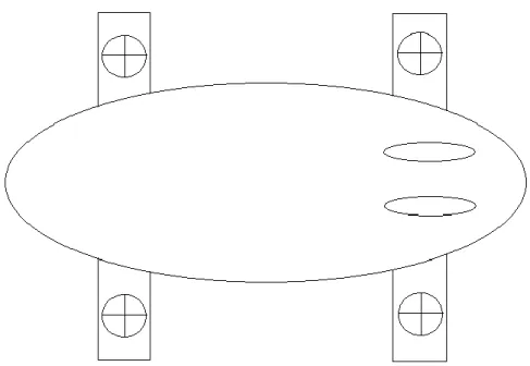
The main concept of this hybrid system of stability and control consists of different elements. The two main parts are the six control surfaces system and the set of four rotors with variable pitch. This way, the final idea combines these two elements so that the rotors are embedded in each one of the four wings. In Fig. 9 a simple conceptual scheme of the airship incorporating this system is shown.
Fig. 9: Simple conceptual scheme of the airship
1Parte da dissertação relevante para efeitos do processo de proteção de invenção referido no Aviso no início deste documento.
20
Six control surfaces system is formed by four wings and two vertical control surfaces. This way, the vertical surfaces are disposed in parallel in the rear of the airship and they act as vertical stabilizers and as rudders providing directional stability and control. The four wings are divided into a front pair and a rear pair where each wing is parallel to the other, forming between the four a rectangular distribution. The purpose of the wings is to provide lateral stability and control as well as longitudinal stability and control by operating simultaneously as elevator and as aileron. In addition, the contribution of the wings to create dynamic lift is also important. The profiles of the control surfaces are symmetrical because their main objective is to provide stability and control.
Furthermore, the four rotor system will be embedded into the wings also forming the rectangular distribution, which corresponds to the conventional X distribution used in quad rotors. These rotors incorporate variable pitch propellers, because as seen in chapter 2, they present different advantages over fixed pitch propellers. Moreover, each rotor rotates around an axis in order to the thrust were vectorized, but that part of the concept is included in future work. Thus, the objective of the system of variable pitch rotors is to stabilize the airship autonomously for stationary flight or at very low speed maneuvers as well as to control the airship in this maneuvers at low speed or even at higher speed ones together with the six surfaces system.
In order to successfully tackle the operational requirements (vertical take-off, stationary flight, cruise ...), it was necessary an observational study of the real behavior of the airship through different tests / trials. These two main stability and control systems were separated to simplify this observational study. Thus, four different prototypes were constructed, where two of them were utilized to test the six surfaces system and the other two were utilized to test the rotors system. In addition, three of them were a similar scale model of the conceptual design shown previously (with some simplifications).
3.2.
Prototype 1
Introduction
Prototype 1 is a scale model of the final design with some simplifications. First, this prototype does not have any internal structure, but it is the blimp itself which guarantees the shape. The other great simplification, and in this case extremely important, is the absence of rotors on the wings, being lift fully obtained by helium and dynamic lift generated by all the control surfaces.
Thus, the airship is primarily a blimp of 3.5 meters in length with a configuration of four wings and two vertical stabilizers and a pusher propeller configuration.
21
Structure and Construction
The fundamental structural part of this first prototype consists of a PVC blimp with dimensions of 3.5 m long, occupying a volume of 3.5 m3. So in addition to the structural
component, the blimp serves another indispensable role, because it will allow to hold the helium inside and thus obtain lift. This total volume is crucial in order to calculate the amount of helium as will be seen later.
Since this is a prototype with a major dimension and a round shape, a cradle was necessary to be built in order to be able to work with guarantees. This cradle is very simple and it is based on two extruded polystyrene pieces appropriated to the blimp shape, placed in parallel (one front and one rear) where the blimp is placed, connected by two beams on each side.
The construction of the two vertical stabilizers were also made of extruded polystyrene and the profile was designed in a specific software called Profili and cut with a hot wire machine, by using another software called CNC controller. The two stabilizers are equal, with 400 mm long and 250 mm of chord, and being the aerodynamic profile the NACA 0012. Each vertical stabilizer has a moving area so you control the yaw of the airship in cruising as well. This rudder has a length of 300 mm and 100 mm of chord and it is driven by a servo embedded in the stabilizer itself. Once the two stabilizers were built, it was necessary to adapt the bottom of each one to the curvature of the blimp in order to fix on this. The fixing system should allow to remove these surfaces and it was a combination of two elements. The first element is a strip of Velcro attached to the bottom of each stabilizer with their opposite side attached to the surface of the blimp; this ensures that after each positioning they are always placed in the same position. The second element is a tensioning wire of Dynamo which can keep both stabilizers in a fixed position (relative to vertical) and a given distance, then the wire was locked at crossing each stabilizer to be attached to this with epoxy resin. Thus, the wire goes from one side of the airship to a stabilizer, from that stabilizer to another one and finally to the other side, forming a sufficiently rigid structure.
For weight reasons and because the vertical stabilizers are in the back, holes were made in the fixed part of each stabilizer in order to reduce the weight and advance the center of mass. These holes were covered with seal tape in order to maintain the aerodynamic surface. Likewise, the wings are of extruded polystyrene, as well as the holding part that is coupled to the airship. Therefore, there are two different parts to assemble the four wings: a fixed part and a movable part, which constitutes the wing itself.
The four wings have the same dimensions, having a chord of 350 mm and a length of 600 mm. Since the four surfaces have a main purpose of control, they have a symmetrical profile NACA 0014, being able to provide lift for positive angles of attack in cruising and/or drag with negative angles. Each wing has an aluminum beam embedded into the polystyrene to allow rotation; this movement is articulated by a servo, which in this case was embedded into the
22
fixed part and acts through an aluminum wire between the own servo and a carbon fiber piece linked to the aluminum beam part.
For the pair of rear wings the same process of holes than vertical stabilizers was made in order to continue moving forward the center of mass. According to an initial estimation, it was possible to decrease between 30-50g per wing with this operation.
Fixed parts are different for each pair of wings (front pair and rear pair), then, in addition to allow fixation of the wings, they also allow the placement of each wing (moving part) in different positions. Thus, the front pair of supports have three different positions for positioning the wings, which are defined by three aluminum pipes tubes where the beam of each wing fits. In the case of the rear supports, they have only two positions using the same system, because, as will be seen later, being away from the center of mass less variation of its position is needed to get different results. Furthermore, these supports must also be removable and have a double fixing system to ensure the rigidity of the structure in order to avoid fluctuations during the flight. The used solution was a combination of double sided tape on the opposite side of the support and on the blimp with the placement of Velcro reinforcements strengthened with a carbon fiber sheet. As carbon flexibility is limited, two curved surfaces were built on each side of the support that make the link between the two elements.
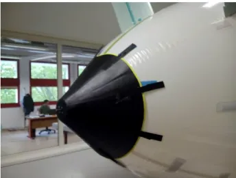
The pusher motor configuration forced the construction of a structure to keep it in a fixed position and, in turn, able to resist twisting and vibration. For this, a laminate carbon cone was built and it was fixed to the back, improving even the streamline of the airship. The cone has a diameter of 400 mm at the base and 75 mm on the top surface, where it has an extra carbon plate in order to fix the motor to that place. By being the gas inlet valve located in the same place, a removable union and easy to implement method were required. As this is a circular structure, a circular ten Velcro straps reinforced with a carbon sheet system presents a solution that meets the operational requirements. In fig. 10the final outcome of the piece is shown in detail once finished.
23
The chosen motor for this first prototype was the NTM prop drive 35-48 900kv together with a three-blade propeller Master Airscrew t3020. This propeller+motor configuration ensured the power required for any performance, especially for take-off tests where maximum power available is used.
In order to control the six servos and motor a wiring distribution was placed throughout the airship, converging these ones in the same place. For reasons of the position of the center of mass, the controller, the ESC and the batteries are positioned at the front of the airship, so that the wiring joins the bottom midline and it is fixed with duct tape. Having to place these components on the front means having a set of three wires linking the motor with the ESC+Battery set traveling from end to end of the airship. The problem of this is the increased weight caused by the required thickness of the wires due to the high current which passes through them.
Finally, being a prototype for cruising, the construction of a landing gear was necessary. The landing gear is formed by two structures of extruded polystyrene placed in parallel at the bottom of the airship and with an approximate length of 1500 mm. These structures have the shape of the airship to perfectly fit to it with the use of double-sided tape. Each one of the two structures has a forward wheel and another wheel back, thus formed a rectangle of four wheels perfectly stable. To ensure the distance between the wheels, the structures were stressed with Dynamo in a similar way than used in the vertical stabilizer solution.
In fig. 11prototype 1 assembled without the motor support before the first tests is shown.