Adv. Radio Sci., 9, 107–110, 2011 www.adv-radio-sci.net/9/107/2011/ doi:10.5194/ars-9-107-2011
© Author(s) 2011. CC Attribution 3.0 License.
Advances in
Radio Science
An uncooled VGA-IRFPA with novel readout architecture
D. W ¨urfel, M. Ruß, R. Lerch, D. Weiler, P. Yang, and H. Vogt
Fraunhofer Institute for Microelectronic Circuits and Systems, Duisburg, Germany
Abstract. An uncooled VGA Infrared Focal Plane Array (IRFPA) based on microbolometers with a pixel pitch of 25 µm for thermal imaging applications is presented. The IRFPA has a 16-bit digital video data output at a frame rate of 30 Hz. Thousands of Analog to Digital Converters (ADCs) are located under the microbolometer array. One ADC con-sists of a Sigma-Delta-Modulator (SDM) of 2nd order and a decimation filter. It is multiplexed for a certain amount of microbolometers arranged in a so called “cluster”. In the 1st stage of the SDM the microbolometer current is integrated time-continuously. The feedback is applied using a switch-able current source. First measurements of Noise Equivalent Temperature Difference (NETD) as a key parameter for IRF-PAs will be presented.
1 Introduction
Low-cost thermal imaging is dominated by uncooled infrared focal plane arrays (IRFPAs) using microbolometers based on vanadium oxide (Blackwell et al., 2008) or amorphous sili-con (Durand et al., 2009) as the sensing material. According to Plank’s law, each body with a temperature above abso-lute zero point emits electro-magnetic radiation. The wave-length and intensity depends on the temperature of the body. For example, a body at a temperature of 300 K has its maxi-mum emittance at a wavelength of approx. 10 µm. FIR im-ager uses the IR-radiation of a warm body in the wavelength range between 8...14 µm. The FIR-sensitive element is the microbolometer which changes its resistance by absorbing the radiation of a warm body. Uncooled IRFPAs operate at ambient temperature and benefit from the abdication of a Stirling cooler in terms of low-cost, low power dissipation,
Correspondence to:D. W¨urfel ([email protected])
Fig. 1.SEM-photo of a microbolometer constructed at Fraunhofer IMS.
low weight, and reduced volume. Typical applications for IRFPAs are thermal imaging and pedestrian detection for au-tomotive driving assistance systems, fire fighting, biological imagery, or military applications like target recognition.
2 The microbolometer
The microbolometer is fabricated by post-processing on CMOS wafers in Fraunhofer IMS Microsystem Lab. The realization of a microbolometer is shown in Fig. 1. A mi-cromachined membrane consisting of amorphous silicon is suspended by two via stacks of metal from the CMOS sub-strate. The membrane forms with two other layers a good interferometric structure for radiation absorption. On top of the membrane an antireflection layer with a sheet resistance of 377/sq is deposited. The bottom structure consists of a nearly perfect reflecting metal layer (Ruß et al., 2007). To increase the thermal resistance the membrane is fixed by two small legs. The distance between membrane and reflection metal reaches an optimum for one quarter of the radiation
108 D. W¨urfel et al.: An uncooled VGA-IRFPA with novel readout architecture
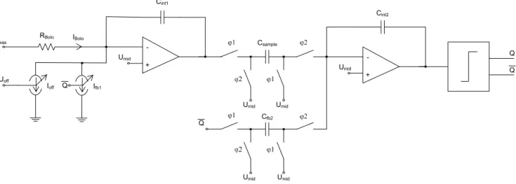
Fig. 2.Schematic of used 2nd Order SDM.
Fig. 3.Model of a 3rd Order SINC-Filter.
Fig. 4.Layout of a cluster (some metal layers are omitted for clarity).
wavelength. To reduce thermal losses by gas conduction a vacuum package is required. The microbolometer converts the infrared radiation into heat energy and this induces a tem-perature rise resulting in a change of the electrical resistance. The microbolometers are arranged in an array with a pixel pitch of 25 µm.
3 The novel readout architecture
The novel readout architecture depicted in Fig. 2 bases on a 2nd order SDM (Weiler et al., 2010). A SDM has the ad-vantage of reaching high resolutions very easily. The price is sampling speed, because a SDM uses so called “oversam-pling”. Quantisation noise is formed and moved out of the base band to higher frequencies. The output signal of a SDM is a digital bit stream which is fed into a decimation filter. This filter is a low-pass and suppresses the quantisa-tion noise. The sampling speed is reduced while increasing the length of the output word. The SDM together with its decimation filter forms the ADC.
The for readout selected microbolometer is integrated di-rectly into the SDM by closing the corresponding select-switch. Reference Ubias is a constant voltage. The
mi-crobolometer current consisting of an offset part and a signal part is integrated time-continuously. The feedback is applied by a switchable current source. A controllable offset cur-rent source is also included to compensate the offset part of the microbolometer current. The 2nd integrated stage works time-discretely. Because of the multiplexing of the readout circuit for 32 microbolometers a decimation filter with an fi-nite settling time is necessary. So a 3rd order SINC-Filter was chosen for this function. Figure 3 shows a correspond-ing scheme based on (Norsworthy, 1997). It consists of 3 cascaded accumulators which are running at the sampling frequencyfs. Then there is a undersampling stage with
fre-quencyfd. It follow 3 differentiators which are running at
frequencyfd. The amount of 32 microbolometers which are
read out by one ADC (consisting of the SDM and the decima-tion filter) is the result of the minimal area where one ADC can be placed. The ADC is arranged in a cluster consisting of 4 times 8 microbolometer areas. A layout of a cluster is depicted in Fig. 4. Three quarters of the area to the left are occupied by the digital SINC-Filter. The SDM is placed in
D. W¨urfel et al.: An uncooled VGA-IRFPA with novel readout architecture 109
Fig. 5.Distribution of the clusters beneath the microbolometer array.
the right quarter. Beneath the whole microbolometer array approximately 10 000 ADCs are positioned. In Fig 5 in a cut-out the positions of some clusters beneath the array are shown. The digital output from the ADCs is multiplexed to a 16 digital video output interface. The frame rate is 30 Hz. The IRFPA has been fabricated in a 0.35 µm CMOS technol-ogy and bonded on a PCB-board (Fig. 6).
4 First measurement results
For first measurements the chip with microbolometers of the 1st generation was placed in a vacuum chamber with an FIR transparent window. A measured NETD histogram is shown
in Fig. 7. The mean value of the NETD is approximately 150 mK. The value is higher than the design value but it has to be considered that it is the 1st generation of microbolome-ters and the microbolometer resistance failed the goal resis-tance extensively. But for all the VGA-IRFPA works promis-ingly. A picture of a hand has been taken (Fig. 8). It has to be remarked that beside an offset correction no further cor-rection or filter is applied to the picture.
5 Conclusions
A VGA-IRFPA with a novel readout architecture has been presented. It is based on massively parallel use of
110 D. W¨urfel et al.: An uncooled VGA-IRFPA with novel readout architecture
Fig. 6.Photo of the VGA-IRFPA bonded on a PCB-board.
Fig. 7.NETD histogram.
SDM-readout followed by SINC-filters. The pixel-pitch of the microbolometers is 25 µm. First NETD measurement re-sults are shown. In near future better rere-sults with the 2nd generation of microbolometers are expected.
100 200 300 400 500 600
50
100
150
200
250
300
350
400
450
Fig. 8.Picture of a hand taken with the presented VGA-IRFPA.
Acknowledgements. The presented work is part of project “FIRKAM” funded by the German “Bundesministerium fur Bil-dung und Forschung BMBF”. The authors would like to thank the program manager “VDI Technologiezentrum” and the FIRKAM project partners for their helpful information and discussions. We highly appreciate the support of the engineers and technicians of Fraunhofer IMS during design, fabrication, and characterization of the IRFPA.
References
Blackwell, R., Lacroix, D., Bach, T., Ishii, J., Hyland, S., Geneczko, J., Chan, S., Sujlana, B., and Joswick, M.: Uncooled VOx
thermal imaging systems at BAE Systems”, Proc. SPIE, 6940, 694021, 1–8, 2008.
Durand, A., Minassian, C., Tissot, J. L., Vilain, M., Robert, P., Tou-vignon, A., Chiappa, J. M., and Pistre, C.: Uncooled amorphous silicon TEC-less 1/4 VGA IRFPA with 25 µm pixel-pitch for high volume applications, Proc. SPIE, 7298, 72982B, 1–7, 2009. Russ, M., Bauer, J., and Vogt, H.: The geometric design of
mi-crobolometer elements for uncooled focal plane arrays, Proc. SPIE Conference Infrared Technology and Applications XXXIII, 6542, 1–10, 2007.
Weiler, D., Russ, M., W¨urfel, D., Lerch, R., Yang, P., Bauer, J., and Vogt, H.: A digital 25 µm pixel-pitch uncooled amorphous sili-con TEC-less VGA-IRFPA with massive parallel Sigma-Delta-ADC readout, Proc. of SPIE, 7660, 76600S-1-7, 2010.
Norsworthy, S. R., Schreier, R., and Temes, G. C.: Delta-Sigma Data Converters, IEEE Press, 0-7803-1045-4, 1997.