U
NIVERSIDADE DE
L
ISBOA
Faculdade de Ciˆencias
Departamento de Inform´atica
VULNERABILITY DISCOVERY IN POWER LINE
COMMUNICATIONS
Fernando Baptista Leal Alves
Dissertac¸˜ao orientada pelo Prof. Doutor Nuno Fuentecilla Maia Ferreira
Neves e co-orientado pelo Prof. Doutor Alysson Neves Bessani
DISSERTAC
¸ ˜
AO
MESTRADO EM ENGENHARIA INFORM ´
ATICA
Especializac¸˜ao em Arquitectura, Sistemas e Redes de Computadores
Acknowledgements
In first place I thank my advisors for accepting me for this thesis. Both taught me a lot. Prof. Nuno is excellent at raising the bar, and prof. Alysson - who I work with for two and a half years - always provided excellent feedback to improve my work. Thank you for this opportunity. Next to my advisors, I thank Francisco Arag˜ao and Manuel Jos´e Mendonc¸a for the time they spent helping me with the thesis. Francisco provided me with an excellent jump start on hacking, and Manuel introduced me to the world of Linux device drivers. Without their help this work would have never reached this point.
I thank my parents for their support, and a very special thanks to my brother Daniel who listened to me and read a bit of this thesis without understanding a thing, besides being my daily comrade. Next, I thank all my friends for support and company, specially for C´esar Santos, Jo˜ao Caetano, Jo˜ao Vieira, Jos´e Sim˜oes and Soraia Meneses Alarc˜ao, for all the lunch and snack time conversations. The time spent with them allowed me to recharge batteries and keep on working. They also read my thesis, which tested their patience. For all my friends, my thanks.
Last but not (at all!) least, I thank my girlfriend and love Soraia Meneses Alarc˜ao, not only for actually loving me (who knows how), but for being my friend, my companion, and my special little girl. You were always present and lighten my mood with your care. For making my days brighter, thank you.
Funding
This work was partially supported by the EC through project FP7 SEGRID (607109), by national funds of Fundac¸˜ao para a Ciˆencia e a Tecnologia (FCT) through project UID/-CEC/00408/2013 (LaSIGE).
Resumo
A comunicac¸˜ao em powerline ´e uma forma de transmiss˜ao de dados atrav´es da rede el´ectrica. Esta ´e usada para a passagem de corrente e transmiss˜ao de dados, utilizando as-sim a mesma infra-estrutura para duas funcionalidades, ambas essenciais nos dias de hoje. Existem ligac¸˜oes de banda estreita e larga em comunicac¸˜ao por powerline, dependendo da frequˆencia da onda el´ectrica. Devido `a baixa frequˆencia e `a distˆancia entre pontos, em redes industriais existem apenas ligac¸˜oes de banda estreita, providenciando veloci-dades at´e 500kB/s. Em redes caseiras a frequˆencia da onda el´ectrica ´e alta, permitindo comunicac¸˜ao em powerline com velocidades de banda larga (v´arias centenas de MB/s).
Esta forma de comunicac¸˜ao tem dois principais usos: redes dom´esticas e redes indus-triais. Em redes dom´esticas, a comunicac¸˜ao em powerline ´e utilizada para estender uma ligac¸˜ao Internet j´a existente, atrav´es dos fios el´ectricos de uma casa. O objectivo ´e obter conectividade em qualquer ponto de uma casa sem recorrer a repetidores, redes sem fios, ou `a instalac¸˜ao de novos cabos. Para este efeito s˜ao utilizados adaptadores de powerline, que s˜ao ligados `as tomadas el´ectricas. O router que serve de ligac¸˜ao `a internet ´e conec-tado atrav´es de um cabo Ethernet a um destes adapconec-tadores. Note-se que este ´e um router comum, obtido atrav´es de uma instalac¸˜ao de internet t´ıpica. Ao estar ligado ao adaptador de powerline, o router transmite dados atrav´es da rede el´ectrica. Outros adaptadores de powerline podem ent˜ao ser ligados a outras tomadas da mesma casa, e a estes podem ser ligados computadores, impressoras, ou quaisquer outros equipamentos que se deseje que tenham uma ligac¸˜ao `a rede, obtendo sinal tal como a partir de uma ligac¸˜ao directa ao rou-ter. Assim, a partir de qualquer tomada ´e poss´ıvel obter ligac¸˜ao `a Internet para qualquer computador ou dispositivo caseiro.
As redes industriais s˜ao compostas por v´arios elementos que formam a distribuic¸˜ao de servic¸os num pa´ıs, como ´e o caso da rede el´ectrica, g´as e ´agua, entre outras utilizac¸˜oes. Neste ambiente, a comunicac¸˜ao em powerline permite que a rede el´ectrica j´a existente seja utilizada para a passagem de informac¸˜ao, como leituras de contadores ou o envio de alarmes. Os principais utilizadores da comunicac¸˜ao em powerline s˜ao as companhias el´ectricas, que com esta forma de comunicac¸˜ao podem usar a sua infra-estrutura para fornecer electricidade e obterem leituras autom´aticas de contadores inteligentes (conta-dores com poder de processamento e ligac¸˜oes de rede). Com estas leituras actualiza-das em tempo real, as companhias el´ectricas conseguem ter um controlo elevado sobre o
equil´ıbrio necess´ario entre a produc¸˜ao e o consumo de electricidade. Se este equil´ıbrio n˜ao for mantido, podem ocorrer picos de tens˜ao ou quebras na distribuic¸˜ao el´ectrica, caso haja electricidade na rede a mais ou menos (respectivamente). Os picos de tens˜ao s˜ao capazes de danificar equipamentos ao ponto de ficarem irrepar´aveis. As quebras na distribuic¸˜ao causam a paragem do funcionamento de alguns elementos ligados `a rede el´ectrica. Esta situac¸˜ao pode tamb´em ser perigosa, visto que, por exemplo, comboios el´ectricos requerem um fornecimento continuado de corrente para o seu correcto funcionamento.
Na rede el´ectrica a corrente ´e transmitida atrav´es de uma onda sinusoidal. A modelac¸˜ao desta onda ´e o que permite a comunicac¸˜ao em powerline. `As v´arias amplitudes de onda podem ser atribu´ıdos valores l´ogicos - por exemplo, podemos atribuir `a amplitude m´ınima da onda o valor l´ogico 0 e `a amplitude m´axima o valor l´ogico 1. Outras configurac¸˜oes mais complexas s˜ao poss´ıveis. A onda el´ectrica ´e modulada de modo a que se consi-gam ler os valores pretendidos na amplitude da onda, atingindo assim a passagem de informac¸˜ao na mesma infra-estrutura que providencia electricidade.
As companhias que produzem dispositivos para powerline juntaram-se em alianc¸as, de modo a que todos os dispositivos produzidos pelos membros sejam padronizados e compat´ıveis entre si. Estes standards podem ser de acesso livre ou apenas para membros da alianc¸a. A maioria destes protocolos inclui mecanismos de seguranc¸a. No entanto, alguns destes mecanismos j´a foram demonstrados como sendo inseguros, permitindo (por exemplo) que atacantes controlem a rede ou os dispositivos em si.
Este trabalho ´e orientado `a procura de vulnerabilidades de seguranc¸a em protocolos de powerline. Apresentamos um resumo de alguns dos protocolos usados actualmente, e efectuamos uma descric¸˜ao mais aprofundada do protocolo HomePlug. Este ´e o protocolo escolhido para an´alise neste trabalho, visto ser amplamente usado em ambientes caseiros e por existir um f´acil acesso a adaptores HomePlug. Identific´amos uma vulnerabilidade de desenho presente num dos mecanismos de troca de chaves criptogr´aficas, que permite a um atacante que escute a rede durante a execuc¸˜ao do protocolo obter as principais chaves de rede, conseguindo assim completo acesso `a rede e `a informac¸˜ao trocada nesta.
Para provar na pr´actica esta vulnerabilidade, precisamos de escutar a rede el´ectrica. Dado que n˜ao sabemos construir um dispositivo que ouc¸a a transmiss˜ao de dados na rede el´ectrica, opt´amos por modificar um adaptador j´a existente que corre uma vers˜ao mini-malista de Linux. Efectu´amos com sucesso actualizac¸˜oes ao firmware do adaptador, de modo a conseguirmos acesso remoto com privil´egios de administrador. Por acedermos ao adaptador conseguimos roubar informac¸˜oes e chaves criptogr´aficas, o que s´o por si ´e uma contribuic¸˜ao apesar de n˜ao ser o objectivo deste trabalho. Acesso a um novo elemento da rede permite-nos fazer novos ataques, e como tal apresentamos v´arias possibilidades de ataque `a rede e a dispositivos utilizando adaptadores de powerline.
Neste adaptador analis´amos a execuc¸˜ao do protocolo vulner´avel, corremos um ana-lisador de tr´afego, coloc´amos bin´arios, device drivers, e explicamos como modificar o
n´ucleo e o bootloader. Infelizmente, nenhum dos testes realizados serviu para provar na pr´actica a vulnerabilidade. Apesar de concluirmos que alguma informac¸˜ao do HomePlug chega a user level, as mensagens espec´ıficas do HomePlug continuam encobertas, fora do nosso alcance. Algumas possibilidades ainda est˜ao em aberto para obter estas mensagens s˜ao descritas, sendo uma poss´ıvel continuac¸˜ao deste trabalho.
Palavras-chave: Powerline, Seguranc¸a, Chaves criptogr´aficas, Hacking.
Abstract
Powerline communication (PLC) is a form of data transfer, where the electric infras-tructure is used for both power supply and network connection. PLC can be employed in industrial or home environments. In home environments, powerline is used to extend the internet connectivity through the house’s electric infrastructure. Powerline adapters are connected to a house’s power sockets, and these adapters provide connectivity throughout the house. A router is linked to one of the adapters to establish the connection, and other adapters are used to decode the powerline signal. These adapters provide an easy manner to extend a home network without the use of various routers, Wi-Fi, repeaters or new ca-bles. In industrial environments, PLC is used (for example) to provide real time data about the electric consumption in the electric grid, allowing fine control of the required/used electricity. With this control, electric suppliers produce electricity more efficiently, re-ducing production costs and prices for the final consumers. Device manufacturers created alliances to standardize their products, developing protocols and guidelines to this effect. We present a summary of some of these standards. These protocols include security mea-sures in their specifications (like cryptography), but some protocols have already been proven unsafe. In this work, we study the HomePlug protocol which is commonly used to extend connectivity inside homes. We describe a design vulnerability present in the HomePlug, in one of the cryptographic key exchange mechanisms. An attacker who lis-tens to the medium can steal the critical network keys. To prove this vulnerability, we created a malicious adaptor by updating it with malicious firmware. Although we ran a large battery of tests in the adaptor, we were unable to prove the vulnerability. Never-theless, we provide an insight on a series of attacks that can be done using a malicious adaptor as an attack point, which can be used in the future to extend this work.
Keywords: Powerline, Security, Network keys, Hacking.
Contents
List of Figures xv
List of Tables xvii
1 Introduction 1
1.1 Motivation . . . 4
1.2 Goals . . . 5
1.3 Contributions . . . 6
1.4 Work plan . . . 6
1.5 Structure of the document . . . 8
2 Related work 9 2.1 Home environment standards . . . 9
2.1.1 HD-PLC . . . 10
2.1.2 HomePlug Alliance . . . 10
2.1.3 IEEE 1901 standard . . . 11
2.2 Industrial environment standards . . . 11
2.2.1 DNP3 . . . 11
2.2.2 G3 . . . 12
2.2.3 Meter-BUS . . . 13
2.2.4 Meters and More . . . 13
2.2.5 Open Smart Grid Protocol . . . 13
2.2.6 Powerline Intelligent Metering Evolution . . . 14
2.2.7 Zigbee . . . 14 2.2.8 IEEE 1901.2 standard . . . 14 2.3 Vulnerabilities in PLC . . . 15 2.3.1 DNP3 . . . 15 2.3.2 HomePlug . . . 15 2.3.3 M-BUS . . . 16 2.3.4 OSGP . . . 16 2.3.5 Zigbee . . . 17 xi
2.4 HomePlug protocol and devices . . . 17
2.4.1 HomePlug in practice . . . 17
2.4.2 The HomePlug protocol . . . 18
2.4.3 HomePlug adaptors . . . 23
3 HomePlug key exchange mechanisms and our attack plan 27 3.1 NMK exchange mechanisms . . . 27
3.1.1 Security analysis . . . 29
3.1.2 An alternative more secure to UKE . . . 30
3.2 Exposing the UKE security flaw . . . 31
3.2.1 The Devolo dLAN WiFi 500 powerline adaptor . . . 32
4 Implementation and evaluation 35 4.1 Experimental setup . . . 35
4.2 Modifying the Devolo dLAN 500 WiFi . . . 36
4.2.1 Extract firmware . . . 36
4.2.2 Modifying/adding files . . . 37
4.2.3 Rebuilding the firmware . . . 37
4.2.4 Bypassing the security . . . 37
4.2.5 Updating the target adaptor . . . 38
4.3 Obtaining access to the adaptor . . . 38
4.4 Execution flow of the UKE protocol on our adaptor . . . 40
4.5 Running binaries on the adaptor . . . 42
4.5.1 Cross-compiling . . . 42
4.5.2 Cross-compiling tcpdump . . . 44
4.5.3 Cross-compiled binaries results . . . 44
4.6 Adding drivers . . . 46
4.6.1 Kernel, kernel objects, drivers, and physical/Ethernet drivers . . . 46
4.6.2 Cross-compiling drivers . . . 47
4.6.3 Cross-compiling dvlbutton . . . 47
4.6.4 Cross-compiling a network driver . . . 49
4.6.5 Testing DSA driver . . . 50
4.7 Changing kernel/bootloader . . . 52
4.8 Discussion . . . 53
5 Conclusions 55 5.1 Future work . . . 56
A UKE details 59
B Devolo dLAN 500 Wifi update sequence 63
C Makefiles 67
C.1 Simple native Makefile . . . 67
C.2 Simple cross-compiling Makefile . . . 67
C.3 Makefile for dvlbutton . . . 68
C.4 Makefile for DSA driver . . . 68
Glossary 73
Bibliography 82
List of Figures
1.1 Example of a simple powerline network connecting a computer and an
ISP router. . . 2
1.2 Example of a sinusoidal modulation to transmit data. . . 3
2.1 Distribution of PLC protocols across Europe. . . 12
2.2 Examples of powerline adaptors. . . 18
2.3 Practical example of a simple powerline network. . . 19
2.4 Example of a complex powerline connection with two networks. . . 20
2.5 Examples of the logical interface isolation and the HomePlug network layers. . . 21
3.1 Comparison of NDE and NUD. . . 28
3.2 Diagram of the UKE protocol. . . 30
3.3 Proposed solution to the UKE vulnerability. . . 31
4.1 Representation of our experimental setups. . . 36
B.1 Web update sequence (1). . . 63
B.2 Web update sequence (2). . . 64
B.3 Web update sequence (3). . . 65
B.4 Web update sequence (4). . . 66
List of Tables
1.1 Comparison between the various technologies used to extend connectivity. 2 2.1 PLC standards, publishing alliances, websites and versions/publish dates. 10
3.1 Representation of the firmware update structure. . . 33
4.1 Equivalent native and MIPS cross-compile toolchain GCC calls. . . 43
A.1 UKE message 1. . . 59
A.2 UKE message 2. . . 59
A.3 UKE message 3. . . 60
A.4 UKE message 3 encrypted payload. . . 60
A.5 UKE message 4. . . 61
A.6 UKE message 4 encrypted payload. . . 61
Chapter 1
Introduction
Powerline communication (PLC) is a form of data transfer through the alternate electric current (AC) conductor, using it for both network and power supply [1]. Its main advan-tage is the use of a single infrastructure for these two purposes. The re-use of the electric infrastructure reduces costs, since there is no need for two installations - one for electricity and one for network connectivity. The electric wave has different frequencies depending on the distance between connection points, due to the nature of the electric current and distribution. Connections inside homes have high frequencies (1.8-250 MHz), allowing broadband connections (data rates up to several hundred MB/s), while high voltage ca-bles use low frequencies (3-500 kHz), providing narrowband network (data rates up to 500 KB/s) [1].
Broadband powerline networks are available for household environments. Home PLC offers comfort to users by creating a network using the existing electric infrastructure of the house, which is employed to extend connectivity to the various rooms. The need for this kind of network comes from the typical internet installation case, where an Internet Service Provider (ISP) sets up a router in a division of the house. Devices in this room get internet access by connecting directly to the router with an Ethernet cable, but in the remaining divisions of the house there is no signal. To extend the router’s signal, one can use Wi-Fi (if the router has such capability), signal repeaters (for Wi-Fi), extend new network cables, or powerline. It is also possible to install more routers, but this is typically more expensive and a cheaper solution usually suffices. Powerline adaptors’ main advantages are reliability and simplicity, which is a trade off with some initial cost of buying the equipment. These provide connection speeds ranging from 200Mb/s up to 1200Mb/s depending on the adaptor, but the signal can be affected by many factors that might force a decrease on the bandwidth. Table 1.1 compares some aspects of powerline with other signal extending solutions.
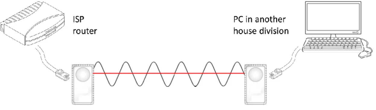
A simple example scenario of extended connectivity using powerline is present in Figure 1.1. An internet connection is provided by the ISP, as we commonly have in our homes. Then, the ISP’s router is connected to one adaptor through an Ethernet cable and
Chapter 1. Introduction 2
Solutions Signal range Cost Signal robustness
Powerline Up to 300m ±e45 for 2 adaptors Influenced by medium noise Wi-fi and Varies; ±e30 Influenced by physical signal repeaters typically ±20m aspects (walls, etc) Cables High Installation cost (±e40) Very high
Extra Routers High Installation + router Equal to cables and/or wi-fi cost (±e70)
Table 1.1: Comparison between the various technologies used to extend connectivity. this adaptor is linked to the power strip through a power plug. Somewhere else in the house, another adaptor is linked to a power plug on the same power strip. Note that in home environments, there is typically only one power strip throughout all rooms. Finally, the computer is connected to the second adaptor, gaining access to the router without installing any extra cables through the house. Powerline in home environments can also be used to provide easy integration with the Internet of Things (IoT) [2], since devices (for example, a fridge) can be easily connected to home controllers, and also to the internet.
Figure 1.1: Example of a simple powerline network connecting a computer and an ISP router.
Narrowband powerline is used in industrial environments. These represent electricity distribution, Supervisory Control And Data Acquisition (SCADA) systems [3], and other infrastructure elements that provide services to homes or industries. Industrial powerline networks are used primarily for data collection, and typically cover large geographical areas. The power grid is one of the main industrial environments where powerline com-munication is used. In the power grid, the balance between produced and consumed energy must be kept. If too much energy is being produced, voltage peaks occur. These may damage hardware circuits, typically shutting them down and possibly impairing them beyond repair. On the other hand, if too little energy is injected on the grid, a power out-age may happen, meaning that there is not enough energy for all connected elements and some of these will shut down due to lack of power. Both events are problematic and can affect society in general. For example, electric trains require a continuous electric supply to function correctly.
Chapter 1. Introduction 3
For a better control of the energy produced/consumed, electric utilities are replacing classic electric meters with smart meters [4]. These meters use powerline communica-tion to provide periodic readings to the utilities, transmitting a more accurate value of how much energy is being demanded on the power grid at all times. By knowing how much energy is necessary, power generation can be adjusted to match the demands. This fine control over the electric production improves the safety of the power grid, as well as reducing electric generation costs - which should also mean decreased costs for the consumers.
Nowadays, companies have organized themselves in alliances to define PLC standards for their products, ensuring that all devices created by the members are compatible. Most of them focus either on home or industrial networks. For instance, the PRIME alliance defines a standard for industrial networks (see Chapter 2 for other examples).
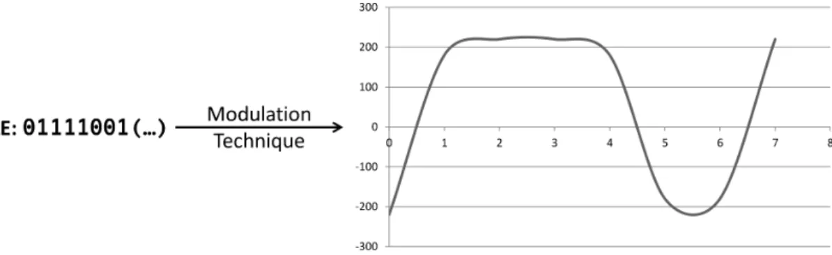
The AC electric supply is defined by a voltage oscillation according to a sinusoidal function [5]. This sinusoidal defines the minimum/maximum voltage values and the fre-quency of the electric wave. Powerline communication is possible by using this sinu-soidal, modulating the wave to control its behaviour and read logical values from the amplitude of the wave. Given maximum wave amplitudes −α and α, then −α could be interpreted as binary 0 and α as binary 1. The wave would be modulated so that the peaks −α and α would match the bits of the transmitted data. A simple example is illustrated in Figure 1.2. In the amplitude of the wave we can read logical values that correspond to the bits of a file to be transmitted (using α = 220, which is the typical voltage value supplied in our homes).
Figure 1.2: Example of a sinusoidal modulation to transmit data.
Other configurations are possible by modulating the wave and reading various logical values. Orthogonal frequency-division multiplexing (OFDM) [6, 7] is one of the princi-pal techniques used in powerline communications to modulate the sinusoidal wave. It is a popular modulation technique that is used in several contexts like digital television and audio broadcasting, DSL Internet access, wireless networks, and 4G mobile communica-tions. It is the modulation technique that prevents devices connected to the circuit from being affected by the changes to the sinusoidal wave. An equilibrium between the positive
Chapter 1. Introduction 4
and negative voltages must be kept, or otherwise the modulation will cause voltage peaks that can damage circuits.
The wave frequency and modulation technique are the key factors that influence the transmission speed of the powerline. Other factors like the quality of the cables and the noise imprinted by devices connected to power supply [8] also influence the transmission speed (the higher the noise, the lower the speed).
1.1
Motivation
The powerline network can be a sensible component because it might transmit critical in-formation. In industrial environments is sent information used to control heavy machinery and critical services over the powerline. For example, on the power grid, the network is used to transmit electric consumption readings and commands that are used to change the behaviour of field units (e.g., circuit breakers). Here, various attacks are possible, includ-ing changinclud-ing the messages in transit or access the data to profile users. In the first case, an attacker tampers with the values sent by smart meters, with the objective of leading the electric utility to believe there is too little or too much power in the grid, causing a power outage or peak respectively. An attacker could also change the electric consump-tion values measured by the meter to make users pay for more or less energy than actually consumed. The second attack can reveal personal information about the consumers. By profiling the electric consumption of a house, an attacker may discover which devices are connected and if there are people present in the house at a given time [9, 10]. In addition, this information could be illegally used for marketing purposes. In home environments, the powerline is used to extend an internet connection. By accessing the powerline an attacker can listen or tamper with the users’ internet traffic.
To protect communications, PLC standards resort to cryptographic approaches, such as encrypting the transmitted messages. To encrypt communications, every participant must possess the same encryption keys. So a reliable method is required to distribute these keys - a key distribution protocol must be robust. If there are flaws in the distribution mechanism, an attacker can compromise the key provisioning and steal the keys to listen to the network, change its messages, or impersonate participants of a network, amongst other attacks. We can classify key distribution methods into two categories: those that use the existing network and those that use an out-of-band mechanism. Methods that use the network always require some previous information exchange or a trusted third party [11]. Examples of these methods are Kerberos [12], signed Diffie-Hellman protocol [13], or Secure Sockets Layer (SSL) [14]. Out-of-band mechanisms require a secondary secure channel to transmit some data (such as identities, nonces - unpredictable random numbers - or keys) that allows the establishment of a secure channel on the insecure network. The out-of-band mechanisms are designed according to the environment in question. A few
Chapter 1. Introduction 5
examples are the users of the devices that exchange the data directly [15], by inputting the data in the devices, or through a dedicated connection (e.g., a separate cable connecting the devices directly).
Poweline communications have already been attacked to some extent [16, 17, 18, 19, 20, 21, 22]. An example is presented next for each environment. In industrial connections, the DNP3 standard can be used for communications in the power grid. This standard has no security measures whatsoever, meaning an attacker with access to the network can freely tamper with every element present in it [16]. In home environments, the Zigbee protocol is vulnerable to denial of service attacks [21].
There are two key factors that make attacking the powerline difficult: access to the specifications, and access to the medium (to attack the protocols). Most protocols are closed, and only the device manufacturers can read them. Most of the information present in this work about these protocols was found on various sites on the internet. To access the powerline medium specific equipment is required, either by building a device or through commercial products. Building such device implies advanced knowledge on hardware circuits and electric components. The other solution is to reverse engineer [23] a com-pliant device. The technical specifications of these devices are mostly closed access as well. This means that attacking the devices or the powerline protocols is mainly black box testing [24] and reverse engineering. Given the underlying difficulties, we believe that any contributions made in this area are significant.
1.2
Goals
With this work we intend to assess the security of a chosen PLC protocol. If vulnerabilities exist, we explain why they are present and provide solutions. The chosen protocol was the HomePlug [25], mainly because it is used extensively in countries in Europe and also due to easy access to compliant devices. Our goals are to make a security analysis of the protocol, and if any flaws are found to prove their existence in theory and practice. For this work, we aim to answer three main research questions:
Q1: Are there any design vulnerabilities in the HomePlug protocol? Q2: Are the key exchange mechanisms of the HomePlug robust?
Q3: Can we break the security of the protocol in a realistic scenario? i.e., Q3.1: Can we infiltrate/modify a HomePlug adaptor?
Q3.2: Can we use this adaptor to demonstrate experimentally the design security flaws that are eventually found?
Chapter 1. Introduction 6
1.3
Contributions
We present an overview of the current powerline standards, both in industrial and home environments. Since our target is the HomePlug protocol, we provide a complete sum-mary of it. This work identifies a flaw in one of the cryptographic key exchange mecha-nisms of HomePlug. An attacker who listens to this key exchange can steal the network keys, and freely infiltrate a HomePlug network. We explain the theory behind the flaw and the planning on how we intended to demonstrate it.
To access the powerline network and do the attack, we needed a HomePlug Sniffer. Since we do not possess the expertise to build a powerline Sniffer, we reverse engineered and hacked a Devolo dLAN 500 WiFi adaptor, which is HomePlug compliant. We chose this device in particular because it runs Linux, an operating system we are familiar with. We provide a complete description of our malicious adaptor’s components and how it works. We introduced malicious software in the adaptor by abusing the update mecha-nism. We obtained root access to the adaptor, gathered its configurations and some critical keys. We also cross-compiled binaries to it [26, 27], changed/added kernel objects, in-cluded a new network driver, and explained how to change its kernel and bootloader. By hacking a powerline adaptor we get access to a new element in a network, which has the perspective of a relay between two points. Using this network position, we provide sug-gestions for a series of potentially dangerous network attacks using powerline adaptors as attack vectors.
We traced the execution of the flawed protocol in our adaptor. However, the adap-tor limits the access to the HomePlug specific messages, which preclude the complete demonstration of the flaw. We present the adaptor’s behaviour during the protocol execu-tion, but somehow it prevents specific messages from being displayed in traffic analysers. We were unable to read the majority of HomePlug messages, including the ones required to demonstrate the identified flaw of the protocol. We also triggered the protocol manually using a program made by us, in an attempt to separate the protocol from its implementa-tion in the adaptor. Unfortunately, this also provided no results. Nevertheless, we believe that information about the HomePlug messages (if not the packets themselves) reach the Linux user space. We enumerate possible changes that can be done in an attempt to obtain the HomePlug messages and disclose the vulnerability.
Concluding, we positively answer research questions Q1, Q2, and Q3.1. Although we traced the execution of the flawed protocol in our adaptor, it was not enough to give Q3.2 an affirmative answer. Consequently, Q3.3 remains unanswered.
1.4
Work plan
This work was developed in LaSIGE - Laborat´orio de Sistemas Inform´aticos de Grande Escala, Departamento de Inform´atica, Faculdade de Ciˆencias, Universidade de Lisboa,
Chapter 1. Introduction 7
under the supervision of professor Nuno Neves and professor Alysson Bessani.
The original work plan starts on 01/10/14 and finishes on 30/06/15, with the following phases:
(1) 01/10 - 28/11: Study of a set of powerline protocols. Selection of a protocol to study for the remainder of the thesis;
(2) 01/12 - 31/12: Analysis of the protocol for security flaws;
(3) 01/01 - 31/01: Design of solutions to detect vulnerabilities in the configuration or implementation of the protocol;
(4) 15/01 - 15/06: Implementation of the solutions and evaluation; (5) 01/04 - 30/06: Description of the work in a report or thesis.
In the original work plan our study target was the PRIME protocol [28, 29], which is used by Energias de Portugal (EDP) for communication in the power grid. To efficiently run practical tests, we proposed a flexible attack tool to streamline the vulnerability testing process. We have access to the PRIME protocol specification because it is open access.
To test if the communication in the Portuguese smart grid is safe, we need access to the specific powerline devices used by EDP, which use a unique implementation of the PRIME protocol. Although smart meters are available on the market, the specific meters produced for EDP are not available for purchase. Obtaining the EDP smart grid elements is a long bureaucratic process, and we did not have access to them in time for this work.
Since we had to choose a new protocol, the HomePlug was our next target. We found the guidelines online [25], and HomePlug compliant devices are easy to obtain - they can be bought in any electronics store - and are fairly cheap (arounde45 for two simple adaptors). We bought some of these adaptors, hoping we could obtain the HomePlug messages on a computer connected to them. After testing with traffic analysers running in a computer connected to one of these adaptors, we discovered that the powerline messages do not leave the powerline network. This means that in order to obtain a Sniffer, we have to either build one or make a HomePlug adaptor malicious. We opted for the second option, and successfully hacked a HomePlug adaptor. Nevertheless, hacking the adaptor was done in place of the attack tool since we did not have time to do both.
There was a small delay in the delivery of this document, because the student while working in this thesis, was also completing his contribution to the BioBankCloud pro-ject [30]. Fernando gathered data and finished writing a paper from October to the start of February, which was when the final article was submitted. Smaller contributions were also provided until the paper was finally accepted, in mid-June [31].
Summarizing, steps (1) and (2) were finished successfully, and the HomePlug protocol is our target. For step (3) we had proposed a flexible attack tool, but later we found we
Chapter 1. Introduction 8
had to build a specific Sniffer for the HomePlug. This lead us to construct the Sniffer in place of the tool. Steps (4) and (5) were also successfully completed, although there was a small delay in the delivery of the thesis.
1.5
Structure of the document
This document is structured as follows:
• Chapter 2 - Related work: Describes some of the existing powerline protocols, their known vulnerabilities and reviews the most important features of the HomePlug protocol.
• Chapter 3 - HomePlug key exchange mechanisms and our attack plan: Presents a the key exchange mechanisms of the HomePlug, the security design flaw we dis-covered, and how we intend to demonstrate it.
• Chapter 4 - Implementation and evaluation: Explains the implementation of our work and the obtained results.
• Chapter 5 - Conclusions: Summarizes the contributions of the thesis and discusses future work.
Chapter 2
Related work
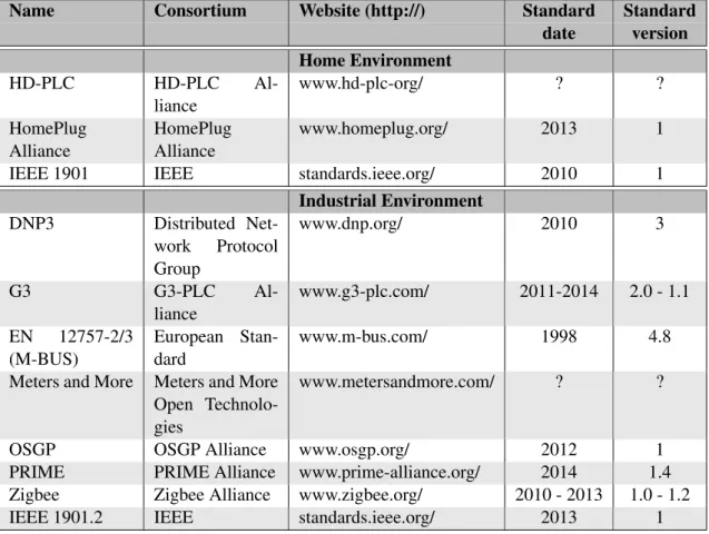
This chapter presents some of the protocols currently in use for PLC. These protocols are employed to guarantee the compliance of the products from various device manufactur-ers. The standards are divided into two categories: standards for industrial and for home environments. PLC in home environments is mainly used to extend network connectivity throughout a house. In industrial environments PLC is utilized to provide connections be-tween various elements of large infrastructures, industry, and services. In Table 2.1 there is a summary of the most relevant PLC protocols. It also mentions the IEEE 1901 [32] and 1902.1 [33] standards, which are two of the base standards for PLC.
Some of the consortia do not provide open access to their guidelines, requiring in some cases a membership fee. Since we do not have such membership, we had no access to the guidelines/protocols documentation, and therefore only a summary is presented of the information that was available in the Internet.
Later in this chapter, we explain some security vulnerabilities found in PLC protocols. The already disclosed security issues were used as inspiration for our security analysis of the HomePlug standard, which is the protocol chosen for this work. An in depth dis-cussion about the HomePlug protocol and its compliant devices is presented in the last section of this chapter.
2.1
Home environment standards
Home environments are characterized by a low voltage/high frequency electric infrastruc-ture. The high frequency of the electric wave allows broadband data rates, like a connec-tion through an Ethernet cable. Thus, in home environments the powerline can be used to extend internet connections and/or to provide broadband connections between devices, such as for media streaming. In the following we briefly describe the main protocols used for this purpose.
Chapter 2. Related work 10
Name Consortium Website (http://) Standard Standard date version Home Environment HD-PLC HD-PLC Al-liance www.hd-plc-org/ ? ? HomePlug Alliance HomePlug Alliance www.homeplug.org/ 2013 1 IEEE 1901 IEEE standards.ieee.org/ 2010 1
Industrial Environment DNP3 Distributed Net-work Protocol Group www.dnp.org/ 2010 3 G3 G3-PLC Al-liance www.g3-plc.com/ 2011-2014 2.0 - 1.1 EN 12757-2/3 (M-BUS) European Stan-dard www.m-bus.com/ 1998 4.8 Meters and More Meters and More
Open Technolo-gies
www.metersandmore.com/ ? ? OSGP OSGP Alliance www.osgp.org/ 2012 1 PRIME PRIME Alliance www.prime-alliance.org/ 2014 1.4 Zigbee Zigbee Alliance www.zigbee.org/ 2010 - 2013 1.0 - 1.2 IEEE 1901.2 IEEE standards.ieee.org/ 2013 1
Table 2.1: PLC standards, publishing alliances, websites and versions/publish dates.
2.1.1
HD-PLC
The focus of HD-PLC is the creation of a simple PLC network in a home environ-ment [34]. The HD-PLC alliance only provides some information on the physical layer of their protocol, which is similar to the physical layer of the HomePlug (e.g., modulation technique). As they maintain their protocols closed, we have no further information about their network topology.
2.1.2
HomePlug Alliance
The HomePlug Alliance provides a standard for PLC in home environments [25, 33]. The guidelines define the usage of an electric infrastructure as a network, resorting to the electrical medium as a network extension. This network can be used by various devices to communicate with each other, just like Ethernet cables or Wi-Fi. A HomePlug network is created by connecting adaptors (small electronic devices that modulate the electric wave to transfer data) to power plugs and pushing a button present in these adaptors. Then, devices (such as computers) can be linked through an Ethernet cable to these adaptors for connectivity.
Chapter 2. Related work 11
devices. These devices can be bought in electronic stores, and are fairly cheap. Also, there is little work done around the HomePlug, which means this is also a great opportunity to find something new that might be relevant to the scientific community.
2.1.3
IEEE 1901 standard
The IEEE 1901 standard is designed for high speed communication devices via pow-erline [33]. This standard focuses on the balanced and efficient use of the powpow-erline communications channel assuring that the desired bandwidth and quality of service may be provided. Security issues related to the privacy of communications are also addressed. The standard describes only the physical layer and the medium access to the data link layer, as defined by Open Systems Interconnection (OSI) model.
2.2
Industrial environment standards
Industrial environments comprise large infrastructures, such as electric distribution. Over large cables, the frequency of the electric wave is low (when compared to home installa-tions), providing only narrowband connections. However, these data rates are sufficient for their purpose, which is transmitting data readings from meters.
Figure 2.1 presents the distribution of these protocols across Europe. Spain uses both PRIME and Meters and More protocols, but the last one is less spread.
2.2.1
DNP3
DNP3 is the third version of the Distributed Network Protocol [35]. The development of DNP is centered on achieving open, standards-based interoperability between substation computers, Remote Terminal Units (RTUs), Intelligent Electronic Devices (IEDs), and master stations of the electric utility. This specification covers multiple communication layers (such as physical and link), and the protocol may interconnect with the TCP/IP protocol to use the Internet with the PLC link. On the application level, DNP uses an event oriented data reporting for improved bandwidth efficiency.
The DNP master gathers control information about its network in the form of events, which are related to noteworthy status changes and classified according to a priority pol-icy. There are four priority Classes, labelled from 0 to 3. The 0 Class is special, since it is defined as the “static” or current status of the monitored data. This means that Class 0 does not contain events, but the status of the device.
The RTUs monitor data points (e.g., smart meters) and generate events when data should be reported. Although RTUs can also be configured to spontaneously report Class 1, 2, or 3 data, in the normal use case RTUs buffer the events. The master queries RTUs for an Integrity Poll (a combined read of Class 1, 2, 3 and 0 data), causing the RTUs to
Chapter 2. Related work 12
Figure 2.1: Distribution of PLC protocols across Europe.
send all gathered events and static data to the Master station. The received data can be processed all together or divided by classes, allowing different priority schemes.
2.2.2
G3
G3 contains a set of guidelines for various smart grid applications, including electric-ity utilities, equipment manufacturers, system integrators, and IT vendors [36, 37]. Fu-ture versions may include other areas, such as power grid management, remote meter management, and electric vehicle charging, as well as supporting interoperability among vendors. The G3 protocol implements IPv6 on top of the PLC MAC layer to emulate a typical internet connection between two elements of the smart grid. This allows the usage of well-known safe and secure protocols on the smart grid. Two network architectures are proposed, one that is centralized and another decentralized. In the centralized archi-tecture, data concentrators simply act as a network gateway and the meters dialogue only with the central servers. In the decentralized architecture, the data concentrators operate as an application relay, with different levels of autonomy.
Chapter 2. Related work 13
2.2.3
Meter-BUS
Meter-BUS (M-BUS) is an European standard (EN 13757-2,3) for the remote reading of meter values [38]. It can be used for multiple types of meters, such as electricity, water or heat. The M-BUS follows a bus topology, where all devices are connected. A master-slave approach is used, where the master coordinates the communications of the master-slaves, which in this case are the meters.
M-BUS is inspired by the OSI model, providing an implementation of the physical, data, network and application layers. The other layers of the OSI model are not applicable to M-BUS, since M-BUS is a bus system and not a network. The physical, data and net-work layers handle the data transmission between master and slaves, while the application layer is oriented to the management of the meters and to data collection.
2.2.4
Meters and More
Meters and More Open Technologies is a group focused on protocols for the smart grid from the distribution side. Their guidelines are oriented towards electric metering and distribution from stations to homes. Meters and More maintains a closed protocol de-scription. However, we obtained some information about the protocol through the Open Meter project [39], which has some project with details about Meters and More (Deliver-ables D5.1, D5.2, and D5.3).
Meters and More uses a tree topology, where data concentrators are in the root posi-tion and act as masters. The non-root non-leaf tree nodes are called “A-Nodes”, and are typically repeaters. “A-Nodes” manage the sub-network bellow them in the tree, act as slaves to the concentrators and as masters to the “B-Nodes”. The “B-Nodes” are the leaf nodes of the tree which are the customer end devices, such as smart meters. The Meters and More communication structure is based on the OSI model, defining physical, MAC and application layers.
2.2.5
Open Smart Grid Protocol
The Open Smart Grid Protocol (OSGP) is designed to support the communication re-quirements of a large scale deployment of smart-grid devices and utility suppliers [40]. OSGP provides its own communication standard inspired by the OSI model, divided in three layers: physical (OSI layer 1), communication (OSI layers 2-6) and application (OSI layer 7). The physical layer handles data transmission over the physical medium. The communication layer ensures communication between parties (like the IP protocol), and implements security on the network. The OSGP application layer offers a “Structured Query Language (SQL)” like language, where all the information of the grid is kept in tables. A global table is maintained in the master, which contains the status of all the elements present in the grid. The various elements of the smart grid make queries to those
Chapter 2. Related work 14
tables to send/receive data. This SQL like architecture aims to provide a highly efficient data transfer between the different devices in the grid.
2.2.6
Powerline Intelligent Metering Evolution
The Powerline Intelligent Metering Evolution (PRIME) Alliance is defining an interop-erable standard for industrial networks [28, 29]. PRIME is designed for the management of the power grid, and is currently deployed in Asia, Oceania, Americas and Europe, including Portugal.
This protocol organizes the network in a tree, where the root node is the coordinator, usually placed on a data concentrator. Other devices in the grid are nodes of the tree. The master controls every node in the network. Branch nodes (as in non-leaf non-root nodes) act as switches for the nodes below them in the tree. Leaf nodes are terminal nodes. Nodes can communicate between themselves (peer-to-peer), with the master node or with broadcasts to the network. When a leaf node receives a connection request from another device trying to join the network, it asks to master for a promotion to become a branch, and then starts routing communication between the requesting node and the master.
PRIME provides its own communication layers inspired by the OSI model, imple-menting physical, MAC, and network (IPv4, and IPv6) layers. Above that, there is an application layer, where the smart grid software is implemented.
2.2.7
Zigbee
The Zigbee Alliance produces standards for connections between smart objects in dif-ferent environments [41]. Zigbee presents a standard for PLC, although the core of its products is wireless communication.
The Smart Energy Profile (which is the Zigbee protocol for smart grids) implements a Representational State Transfer (REST) [42] architecture. It is built around the core actions of get, head, put, post, and delete, with the addition of a lightweight subscription mechanism. This mechanism is used when a client wishes to be notified of changes to a resource on a server.
The objective of this protocol implementation is to avoid distinctions between servers or clients. When a device exposes a resource acts as a server, and when interacts with a resource is a client. This allows a fully flexible network.
2.2.8
IEEE 1901.2 standard
The IEEE 1901.2 standard specifies communications for low-frequency narrowband pow-erline devices [32]. It addresses grid to utility metering, grid automation, and electric vehicle to charging station. Lighting and solar panel PLC are also potential uses of this communications standard. The standard addresses the necessary security requirements
Chapter 2. Related work 15
that assure communication privacy and allow use for security-sensitive services. This standard defines the physical layer and data link layer specifications.
2.3
Vulnerabilities in PLC
Some of the previous protocols have already been successfully attacked (for example DNP3 [16], HomePlug [17, 18], M-BUS [19], OSGP [20], Zigbee [21, 22]). This section explains these attacks.
2.3.1
DNP3
Attacks on DNP3 are particularly worrisome because almost full control of the DNP3 network is possible, due to the non-existence of security mechanisms [16]. DNP3 im-plementations typically do not employ encryption, authentication and authorization, and devices simply assume that all messages are valid.
The DNP infrastructure is composed of a master unit (which is the central controller of the grid), outstation devices and network/communication paths. Ninety-one different attacks against the DNP infrastructure have been identified, with different impact degrees ranging from denial of service to obtaining control of the master unit.
2.3.2
HomePlug
The key implementation of HomePlug AV networks is unsafe [17]. All HomePlug devices have by default the same Network Membership Key (NMK), which is used to control the admission of devices into a network. After a successful admission, a device receives a Network Encryption Key (NEK), which is used to protect communications between devices of the network. Since this key is always the same, a malicious user can enroll into any network using the default NMK and listen to the traffic (since it receives the NEK).
The attack previously described can be further amplified [18]. A third key is used by devices in a HomePlug network, the Device Access Key (DAK). This key is derived from the device’s MAC address, and can be used to force the enrolment of a device into a network. Note the difference between keys: one is used by devices to join a network; the other is used to make a device join a network. The author believes that these MAC addresses/DAK were not supposed to be discoverable. However, since they are, an at-tacker can bring devices into his network, thus eventually obtaining full control of their communications (usually home devices, like computers).
In this thesis, we present other possible attacks to the HomePlug protocol using adap-tors as attack vecadap-tors. Since an adaptor is a relay between two points, by accessing the adaptor and the flowing traffic, an attacker can act as Man-in-the-Middle [11].
Chapter 2. Related work 16
2.3.3
M-BUS
A security analysis of the M-BUS protocol was performed, disclosing a list of major is-sues [19], ranging from inadequate key length to disclosure and manipulation of encrypted message contents:
• The standard recommends a 64-bit key, while the current suggested key size is at least 128-bit [43];
• Inappropriate key and Initialization Vector (IV) [11] derivation may disclose plain-texts [11];
• Missing integrity protection allows the modification of messages without detection; • The synchronization mechanism is not authenticated, and by attacking the system’s
clock an attacker may cause a repetition of the key used in stream cypher [11]; • Due to lack of authentication for network management an attacker can become a
rogue network relay point;
• The M-BUS system possesses alarms for attacks, and an attacker can recognize if these alarms have been triggered - this is useful to known if messages sent to a device contain (in)correct values;
• The key update mechanism is flawed and may lead to key disclosure.
The security analysis classifies M-BUS as insecure and incapable of competing with the current security challenges.
2.3.4
OSGP
A series of vulnerabilities in the OSG protocol have been identified [20]. The encryption and message-authentication mechanisms were designed to be lightweight, which reduces the security robustness. It is possible to completely recover the authentication and en-cryption keys by exploiting weaknesses in the digest function [44] and RC4 stream cipher algorithm [45].
The OSGP digest function does not adhere to any crypto standard and its design does not provide a secure message authentication code (MAC). A robust MAC function is irreversible, but the OSGP digest does not possess this property. RC4 should not be employed due to the known issues [46, 47, 48, 49].
Moreover, the standard does not provide entity authentication on the source of sages. Broadcasts are authenticated using the flawed digest function, which provide mes-sage authentication but not source authentication - a proper digital signature should pro-vide both. Since firmware updates in OSGP are sent through broadcast messages, an at-tacker could send malicious firmware to all devices of the network. The firmware would
Chapter 2. Related work 17
be correctly authenticated with the flawed digest, and since the message source is not verified, the devices accept the update as legitimate.
2.3.5
Zigbee
Zigbee networks are vulnerable to a series of different attacks [21, 22]. The Zigbee speci-fication supports two security levels: High Security (also referred to as Commercial Secu-rity) and Standard Security (also referred to as Residential SecuSecu-rity) [21]. The Standard Security level transmits the network key in plain text during a device registration. An attacker who sniffs the network easily captures the key, and then can listen to all network traffic.
Zigbee devices use nonces (a unique random number) as part of the encryption key for further protection. However, this leaves the network open to the so called Same-Nonce Attack. If an attacker can cause devices to choose the same nonce twice, he will gather information about the plaintext. This attack is possible if the attacker can force devices to reboot to default values, which makes them repeat the nonces.
Zigbee devices are also vulnerable to denial of service attacks. These devices utilize a frame counter to prevent replay attacks, where each time a frame is received the device’s frame counter is updated with the frame’s sequence number. This counter has a maximum value given by a 32-bit counter, and is reset when the network key is refreshed. A frame is discarded if it has a sequence number lower than the counter. An attacker can send a frame with the maximum sequence number, which will be set as the device’s frame counter. From that point on, all frames will be discarded because the frame counter will always have a sequence number higher than the received frames. This attack can be performed even if the frames are encrypted.
The Zigbee devices are also vulnerable to physical attacks, since keys can be stolen with direct access to a Zigbee device [22]. Unless devices are protected from physical tampering, an attacker can steal keys and then emulate the device to obtain access to the network.
2.4
HomePlug protocol and devices
This section describes the most important features of the HomePlug standard. We begin with a simple example of a network created using HomePlug adaptors, and then present the most relevant aspects of the protocol. We also explain the functioning of HomePlug compliant devices and some details of their topology.
Chapter 2. Related work 18
2.4.1
HomePlug in practice
The HomePlug protocol is designed for use inside homes, to ease the extension of net-work connectivity. In the rest of this document, HomePlug complaint equipment will be referred to as adaptors, and other electronic gadgets linked to adaptors for connectivity as devices. Examples of adaptors are displayed in Figure 2.2, and devices are equipment like computers, routers, printers, fridges, and televisions.
(a)Devolo dLAN 500 duo+ (b)D-Link DHP-P309AV (c)TP-Link TL-PA4020PKIT (d)Devolo dLAN 500 WiFi Figure 2.2: Examples of powerline adaptors.
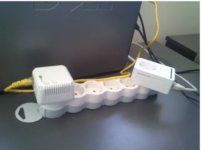
Figure 2.3 shows a practical example of a powerline connection representing our test bed. An Ethernet cable connects the computer to the adaptor on the left. The other adaptor (on the right) is connected to a router through another Ethernet cable. The router is not seen in the figure due to the configuration of the room. The two adaptors communicate through the electric extension, representing two plugs of a house.
To establish a connection between devices (in the figure, between the PC and the router), we couple the adaptors to power plugs, and link the devices to the adaptors. However, this does not suffice. First, the adaptors must establish their own network. The most simple mechanism to establish a HomePlug network is to push the HomePlug buttons of each adaptor - all adaptors are manufactured with at least one button. We push the buttons, wait a short time period, and the network between adaptors is created. Only then the connection between the computer and the router is enabled. In summary, first the adaptors establish a primary connection between themselves, then provide network connectivity to the devices linked to them.
2.4.2
The HomePlug protocol
Since home environments are characterized by low voltage/high frequency electric capa-bilities, it is possible to offer broadband powerline communication between devices. The protocol is focused on providing a simple and secure network extension solution, while being user friendly.
Chapter 2. Related work 19
Figure 2.3: Practical example of a simple powerline network.
HomePlug adaptors establish their own private network, and is through this network that the devices connected to the adaptors exchange the packets. In the following sections we provide an overview of the HomePlug networks.
Establishing a network
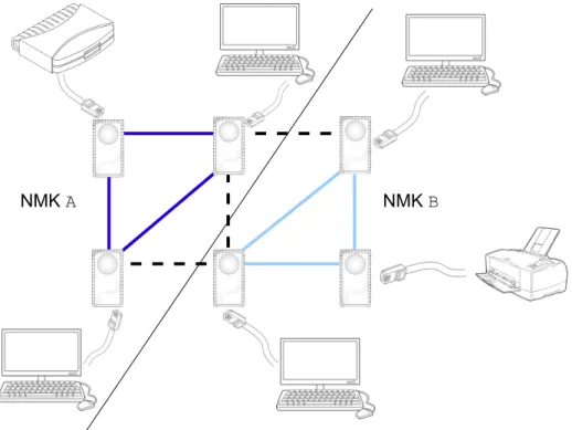
The first step to create a HomePlug network is to connect HomePlug compliant adaptors to power plugs on the same power strip (these adaptors are presented in more detail in Section 2.4.3). adaptors in different power strips are physically isolated, and therefore cannot communicate. Then, a HomePlug network must be established. These are defined by all adaptors possessing the same Network Membership Key (NMK). A network is composed of one or more adaptors. Given n adaptors, any subset of them can be combined to form different networks, with the restriction that an adaptor can only be part of one network. adaptors in different networks are logically isolated from each other. To create networks or add adaptors to an existing network, one of the NMK provisioning methods described in Section 3.1 would be employed. Each network will have its unique Network Identifier (NID), calculated with an hash of the NMK.
Once the adaptors are in the desired network they can communicate among them-selves, and provide connectivity to their devices (e.g., computers, routers, printers).
Fig-Chapter 2. Related work 20
ure 2.4 shows an example of a set of adaptors creating two networks, where the dashed lines represent the separation between powerline networks. Since there is a separation amongst adaptors, the devices connected to them are also logically separated. The devices on the left network are unable to communicate through the powerline with the devices on the right.
NMK A NMK B
Figure 2.4: Example of a complex powerline connection with two networks.
Communication in HomePlug networks
The HomePlug protocol has its foundations in the physical (electrical) medium. As with any physical shared medium, adaptors must communicate in turns to avoid collisions be-tween two or more messages - overlapping messages generate noise and preclude efficient communication. To prevent message tangling, HomePlug defines transmission beacons, during which participants have the medium for themselves. The network coordinator (see below) defines beacon lengths and attributes beacons to the participants in round-robin. Network participants can also ask for more beacons or longer beacons, by sending a re-quest to the coordinator.
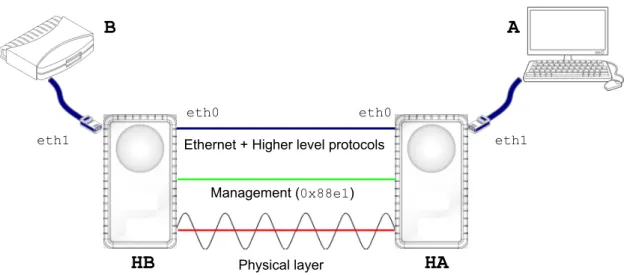
The HomePlug protocols are organized in layers. On top of the physical layer there is an Ethernet layer. Each network participant has a pre-defined MAC address, which uniquely identifies it. Participants communicate with each other through Ethernet mes-sages.
Chapter 2. Related work 21
included in an adaptor. Messages sent by computer A reach the HomePlug participant (adaptor) HA through an Ethernet cable (in interface eth1) and then they are sent through the powerline to adaptor HB (through interface eth0). The adaptors isolate the network interfaces eth0 and eth1, mediating the connection between them. This means that there is no direct access from the computer to the (physical) powerline.
Physical layer Management (0x88e1) Ethernet + Higher level protocols
eth1 eth1
eth0 eth0
A
B
HB
HA
Figure 2.5: Examples of the logical interface isolation and the HomePlug network layers.
Since the HomePlug adaptors control which messages go through a specific inter-face, they can exchange management messages among themselves through the powerline interface, hidden from the devices connected to them. This creates the HomePlug man-agement layer. Manman-agement messages are solely transmitted over the powerline and the adaptors never redirect these messages to the devices connected to them. In addition, in the HomePlug standard it is mentioned that some management messages are meant to be only transmitted over the powerline and never through the Ethernet (MAC layer). This is a security measure, since it prevents computers from sniffing or spoofing management messages. Only adaptors can listen or tamper with these messages, since they have ex-clusive access to the management layer. The management messages exchanged between HomePlug adaptors are normal Ethernet messages, with a specific ethertype (0x88e1). Figure 2.5 presents a visual representation of these layers.
HomePlug network coordinators
Each HomePlug network has a coordinator. The coordinator manages the other adaptors present in the network, and both the physical and the Ethernet layers. It is also the co-ordinator that accepts adaptors into its network. The role of coco-ordinator is dynamic, in the sense that any of the remaining participants can become the new coordinator if the current one leaves the network (depends on adaptor configuration; see Section 2.4.3 for more details).
Chapter 2. Related work 22
The coordinator can decide to separate its network into sub-networks, “for secure distribution of different Network Encryption Keys” (NEK - presented below) [25]. Each sub-network will have its own sub-coordinator, and all the sub-coordinators communicate with the main coordinator for message exchanges that need to cross the sub-networks, as well as for management messages between sub-networks. Each sub-network will have its NMK and NEK. The main coordinator will possess all of the NMKs of the sub-networks it manages. In addition, each network and sub-network has a Network Identifier (NID).
Security
The traffic generated by the devices is encrypted while transferred between adaptors, and integrity is checked (only) at physical level. All key exchange mechanisms define specific keys to encrypt the protocol messages. Most of the management messages exchanged are also encrypted. The HomePlug standard defines multiple encryption keys, each for a different context. Nonces are also used in some management messages to prevent replay-attacks 1 [11]. The encryption algorithm employed by the HomePlug is the Advanced Encryption Standard (AES) [50], which is the current standard for encryption in networks. In the next subsection we give a summary of the most relevant keys. First we present the default keys, placed in adaptors during the manufacturing process. Then we describe the keys to encrypt the frames exchanged in the network, and finally we present the keys to establish private channels between two adaptors.
Default keys
• Device Access Key (DAK): The DAK is a unique key placed in the adaptor during the manufacturing process. Besides identifying the adaptor, the DAK can be used to send the NMK to another adaptor, through the “Providing NMK using DAK” pro-tocol (detailed in Section 3.1). The DAK must never be sent through the network, which means that if adaptor A wants to share the NMK with adaptor B using B’s DAK, A must obtain B’s DAK by some other mean than the network - through the user or some other out-of-band mechanism. This key is used as a MAC encryption key.
• Network Membership Key (NMK): Adaptors always come with a default NMK. The network membership key defines which adaptors are part of a network. Home-Plug defines alternative methods for the transmission of new NMKs (see Section 3.1). It is through the NMK that the NEK is distributed to the participants of a network. NMK is a network encryption key, changed when an adaptor joins a network.
1Attacks where previously sent messages are re-sent by an attacker, re-enacting a previous interaction
Chapter 2. Related work 23
Network encryption keys
• Network Encryption Key (NEK): This key is used to encrypt almost all messages exchanged between adaptors, as only a few management messages are allowed to be sent unencrypted. The traffic generated by the devices (e.g., computers) linked to the adaptors is encrypted with this key when it is transferred over the powerline. The device’s traffic is encrypted before being sent over the powerline and decrypted when leaving it.
Encryption keys for private channels
• Point-to-point Encryption Key (PPEK): This key is used to encrypt point-to-point physical messages. Point-to-point encryption is supported on optional basis by the adaptors. Please, see below the End-to-end Encryption Key.
• Temporary Encryption Key (TEK): The TEK is used to encrypt messages during key exchange protocols on private channels between two adaptors. A new TEK is generated for each instance of a key exchange. TEKs have a limited life span and are never re-used. TEKs are provisioned using the adaptor’s DAK or through the Unicast Key Exchange (described in Section 3.1).
• End-to-end Encryption Key (EEK): This key is used to encrypt point-to-point Ethernet messages. Both this key and the PPEK are used only when two adap-tors wish to establish a private long duration channel between them. This key is distributed using the EDK (see below).
• EEK Distribution Key (EDK): This key’s sole purpose is to distribute the EEK. The message providing an adaptor with the EDK has to be encrypted with the adap-tor’s DAK.
As mentioned in Section 2.4.2, only adaptors have access to the HomePlug manage-ment layer, where network configurations and encryption keys are exchanged. This can be considered a security measure, since it increases the difficulty to attack these messages. Nevertheless, it is possible to build modules capable of accessing the physical layer of powerline communication. An example module has already been built, using specific hardware components and is capable of sniffing simple powerline communications [51].
2.4.3
HomePlug adaptors
HomePlug adaptors are small electronic gadgets that when connected to the same power strip can communicate through the powerline. These adaptors can modulate the electric current’s sinusoidal to create a custom wave. This wave is perceived only by other adap-tors, and does not influence the devices that are connected to a plug just for electric power
Chapter 2. Related work 24
(like televisions). The technique used by these adaptors to modulate the wave is outside the scope of this work.
Adaptors may not work as expected if there are current controlling/modelling devices between them. Devices like Uninterruptible Power Supply (UPSs) may change the mod-ulation created by the adaptors, thus changing/removing the information imprinted in the electric wave. In addition, these adaptors are sensitive to the noise that normally exists in the power strip, as any device that is connected may change the electric sinusoidal [8]. Since the adaptors depend on the quality of the sinusoidal to communicate, noise in the power strip influences its communication speed and range. The quality of the cables of the power strip also impacts the quality of the signal. On environments with noise, the adaptors reduce the communication speed to increase their robustness to errors.
The adaptors have at least one Ethernet plug, and they may have a power plug that can be used just like any other plug on walls. This plug is present for commodity. Since the adaptor must use a plug, it provides one so that users do not “spend” a plug for each adaptor. The Ethernet plug is used to connect the adaptor to other devices, like computers, printers, etc. The adaptors generally have between one to three blinking light emitting diodes (leds). The leds usually indicate if the adaptor is on, if it is connected to other adaptors and if there is a device connected to it. The adaptors also possess a button. A short press on the button makes an adaptor join/create a HomePlug network. A long press removes the adaptor from its current network. The purpose of the button is further explained in Section 3.1.
There are also HomePlug adaptors with Wi-Fi capabilities. These adaptors provide a Wi-Fi signal just as a normal router, except that it gets its Internet connection from the powerline. They may also contain Ethernet plugs.
Device organization
The HomePlug adaptors that were analysed had chips made by Qualcomm Atheros [52], which is a developer of semiconductors for network communications. Besides produc-ing the chips, Qualcomm released an open source toolkit called Open Powerline Toolkit (open-plc) [53]. This software suite is used to interact with these chips, which are config-ured using two files with names ending in .pib and .nvm.
The Parameter Information Block (PIB, stored in a .pib file) contains configurable attributes of the adaptor. The main attributes are the adaptor’s MAC address, the keys DAK and NMK, and the coordinator status. Note that the coordinator status attribute is not discriminated in the standard but defined by Qualcomm. Adaptors can be in one of the following five statuses:
• Auto: The adaptor joins existing networks if capable and in alternative creates its own network.
Chapter 2. Related work 25
• Never: The adaptor never takes the role of coordinator, which means that the adap-tor will never create its own network.
• Always: The adaptor will always try to be the coordinator of the network where it is present. If this is not possible, it will form its own network.
• User Assigned: The user chooses the role of the adaptor, meaning it is not in a preconfigured status.
• Covert: We could not find what this status means.
The .nvm is a file that stores the firmware for the chip. This file is divided into six components: Chain Manifest, Memory Control Applet, Custom Module Update Applet, Power Management Applet, Generic Image, and Runtime Firmware. The information about the .nvm was retrieved from the chknvm tool that is included in the open-plc toolkit. We have no further details about the chip’s firmware, since its structure is closed source. As stated in chknvm’s manual: “Qualcomm Atheros firmware file structure and content is proprietary to Qualcomm Atheros, Ocala FL USA. Consequently, public infor-mation is not available.”
Typical HomePlug adaptors only have a MAC address and as uploadable files, a .pib and an .nvm. However, the HomePlug adaptors with Wi-Fi capabilities require extra internal management - the Devolo adaptors with Wi-Fi capabilities we analysed include a minimalist Linux kernel and a file system.