Universidade de Lisboa
Faculdade de Ciências
Departamento de Física
Robotic Implantation of Intracerebral Electrodes
for Deep Brain Stimulation and Stereo-EEG
Mestrado Integrado em Engenharia Biomédica e Biofísica
Perfil em Engenharia Clínica e Instrumenção Médica
Carolina Marques Lourenço de Almeida Vale
Dissertação orientada por:
Prof. Dr. Hugo Ferreira, Instituto de Biofísica e Engenharia Biomédica, Departa-mento de Física da Universidade de Lisboa
Prof. Dra. Estela Bicho Erlangen, Laboratório de Robótica Móvel e Antropomórfica, Departamento de Electrónica Industrial da Universidade do Minho
Universidade de Lisboa
Faculdade de Ciências
Departamento de Física
Robotic Implantation of Intracerebral Electrodes
for Deep Brain Stimulation and Stereo-EEG:
Development of a control approach of a robotic manipulator
for Neurosurgery assistance.
Mestrado Integrado em Engenharia Biomédica e Biofísica
Carolina Marques Lourenço de Almeida Vale
Dissertação orientada por:
Prof. Dr. Hugo Ferreira, Instituto de Biofísica e Engenharia Biomédica, Departa-mento de Física da Universidade de Lisboa
Prof. Dra. Estela Bicho Erlangen, Laboratório de Robótica Móvel e Antropomórfica, Departamento de Electrónica Industrial da Universidade do Minho
To my family and love ones, with a special dedication to my great- grandmother Rosa who I will remember, always
Acknowledgments
Completing my MSc. degree was definitely a major challenge. The year I spent in
Guimarães finishing my master’s, was marked by very special and enriching moments which I will never forget. First of all, I want to say that it was a privilege to spend this year at
the Mobile and Anthropomorphic Robotics Laboratory (MARL), surrounded by amazing people who guided me, and helped me at all times.
I start by thanking Professor Hugo Ferreira, my college Medical Robotics professor and the-sis internal supervisor, for sharing his knowledge about the amazing field of Robotics, and
valuable information provided that led me to live this amazing and enriching experience. I want to express a very special thanks to Professor Estela Bicho, who enabled the
develop-ment of this project and gave me the opportunity of working at her laboratory, for her warm welcoming and extent knowledge, experience and guidance provided. To my supervisor,
colleague and friend Carlos Faria, who guided me in all stages of project development, for his eternal patience, knowledge shared, and also for the silly moments we spent together. I
want to thank as well my lab colleagues Emanuel Sousa, Flora Ferreira, Gianpaolo Gulletta, Luís Louro, Rui Silva, Tiago Malheiro, Toni Machado and Weronika Wojtak for their
friendship and guidance provided during this year, and for all the amazing moments we spent together.
I thank Dr. Manuel Rito and the Coimbra Hospitals Neurosurgery Service for the opportu-nity to visit the facility to attend a real surgery, and also for the availability demonstrated
by the medical team involved and the explanations provided to our numerous doubts about the ongoing procedure. I thank Dr. Rito for both sharing his knowledge and experience,
which supported project development. I also thank António Ferreira Rito & Filhos company who fabricated in a short period of time the end-effector tools needed for our tests with
the robotic system.
I want to thank our robot’s company supplier, Roboplan, for the welcoming environment
and assistance provided when performing our first tests with the robotic system at the company, and for borrowing us the Motoman MH5 robot system for a month to assess the results of our developed robot approach.
Finally, I would like to express a very special thanks to my family, my friends and love one for all they represent in my life; for the unconditional love, and support they have given
Resumo
Esta tese de mestrado foca-se no desenvolvimento de um sistema robótico capaz de assistir
neurocirurgiões em procedimentos estereotáxicos minimamente invasivos de Estimulação Cerebral Profunda (DBS) e Stereo-electroencefalografia (Stereo-EEG ou SEEG). O primeiro
procedimento (DBS) visa a implantação de electrodos que estimulam estruturas profundas do cérebro, para melhoramento dos sintomas causados por doenças neurológicas comuns,
como é o caso da doença de Parkinson. Por outro lado, no segundo procedimento cirúrgico (SEEG), electrodos intracerebrais são inseridos para delimitação da zona epileptogênica
- zona onde são despultadas as crises epilépticas - em pacientes que sofrem de Epilepsia, através do monitoramento da actividade cerebral nessa zona. Aquando da realização de
procedimentos cirúrgicos deste tipo, o robô deve ser capaz de posicionar os instrumentos cirúrgicos necessários (tais como, electrodos, trepano neurocirúrgico) numa determinada
posição e orientação, segundo trajectórias específicas, decididas pela equipa médica com o apoio de software de imagem e planeamento cirúrgico. O desafio deste projecto passa
por usar um sistema robótico real fazendo-o actuar como um assistente passivo em inter-venções estereotáxicas de cirurgia cerebral. Este sistema é capaz de se posicionar segundo
trajectórias bem definidas, permitindo deste modo ao neurocirurgião actuar segundo es-sas mesmas trajectórias (para realização de tarefas tais como a inserção de electrodos
intracerebrais e perfuração do crânio).
Numa fase introdutória desta dissertação, é realizada uma breve análise acerca do
impacto causado por doenças neurológicas comuns na sociedade de hoje, bem como a identificação de limitações gerais ligadas a procedimentos tradicionais (não robotizados) de
DBS e SEEG. O facto de se tratarem de procedimentos cirúrgicos bastante demorados, acabam por se tornar desgastantes quer para neurocirurgião quer para a equipa médica
responsável. O uso de sistemas robóticos tornam o procedimento cirúrgico menos exigente para o neurocirurgião e equipa médica quer fisicamente, quer cognitivamente, uma vez que
o robô pode assumir diversas tarefas nomeadamente, de posicionamento e manipulação dos instrumentos cirúrgicos necessários, não estando sujeitos a erros devido ao cansaço. Esta
acção cooperativa entre o neurocirurgião e o sistema robótico pode assegurar a eficiência do tratamento, uma vez que junta a capacidade de julgamento do neurocirurgião baseado
na sua experiência, com as vantagens trazidas por um sistema robótico, nomeadamente o aumento da precisão, e a sua maior estabilidade e flexibilidade ao se posicionarem de
acordo com as trajectóricas necessárias.
Identificado o problema actual, bem como a motivação, é descrito o conceito de
neurocirurgia estereotáxica, seguido de um estudo da evolução dos equipamentos usados neste tipo de cirurgias. Procedimentos estereotáxicos neurocirúrgicos requerem a criação
de um sistema de coordenadas, para mapeamento de estruturas neurológicas segundo este, tornando possível a identificação dos alvos cirúrgicos a atingir e consecutivo posicionamento
do equipamento. É adquirido um conhecimento mais aprofundado acerca de procedimentos cirúrgicos deste tipo, através da descrição de uma intervenção estereotáxica comum - de
DBS. Posto isto, são identificados os problemas/limitações associados ao uso de frames estereotáxicas - dispositivos actualmente utilizados para definição das trajectórias até
ao alvo. São finalmente reconhecidas e descritas em detalhe as vantagens de usar um sistema robótico como substituto deste dispositivos (frames estereotáxicas), em intervenções
estereotáxicas de cirurgia cerebral.
É elaborado um estado da arte sobre robôs neurocirúrgicos, para assim se perceber o que tem sido feito e o que pode ser melhorado. Sistemas robóticos actuais apresentam
características semelhantes, como a capacidade que têm em se posicionar de acordo com trajectórias específicas, mas também diversas limitações. Desta análise feita tendo em
conta as características de sistemas actuais, são identificadas as mais procuradas num sistema robótico para assistência em neurocirurgia estereotáxica. De entre as principais
características destacam-se a robustez para segurar e orientar com precisão instrumentação cirúrgica, a flexibilidade em alcançar trajectórias cirúrgias específicas, a facilidade de
implementação em instituições hospitalares, a mobilidade na sala de operações, de entre outras mais específicas.
Para desenvolvimento de um sistema robótico deste género, conceitos teóricos fun-damentais de robótica, nomeadamente de transformações no espaço e formulação da
cinemática do robô, são primeiramente aprendidos usando uma ferramenta de simulação desenvolvida ao encontro de neurocirurgia estereotáxica. Identificadas as suas
potenciali-dades enquanto ferramenta de aprendizagem, nomeadamente pelo facto de apresentar um exemplo prático concreto bem estruturado - de um caso real de neurocirurgia estereotáxica
- e uma tarefa intimimamente ligada a muitos conceitos de robótica; é, consequentemente, criado um projecto educacional de aprendizagem experimental, apropriado para ensinar
aprendizagem criado torna-se evidente aquando da análise das notas obtidas pelos alunos em exame (desenhado para avaliação dos conhecimentos adquiridos por estes), da sua taxa
de sucesso, quando em comparação com anos anteriores; assim como, pela análise de dados obtidos através de um questionário realizados aos alunos e de um inquérito institucional
igualmente dirigidos aos alunos que experienciaram a ferramenta de aprendizagem nesse ano.
De seguida, é desenvolvido um método de registo do rôbo ao espaço cirúrgico baseado no contacto com diversos pontos de referência nos dois sistemas de coordenadas (do robô e
de cirurgia). Este método simples de registo é utilizado tendo em conta tratar-se de uma primeira abordagem experimental. O robô manipulator pode assim utilizar o planeamento
realizado para se posicionar de acordo com trajectórias específicas que irão permitir atingir o alvo cirúrgico. Os electrodos são implantados com recurso a uma ferramenta de guia que
é fixa na extremedidade do robô e que permite guiá-los até ao alvo.
É criada uma plataforma de comunicação com um sistema robótico real - Yaskawa Mo-toman MH5 - e desenvolvida uma aplicação para controlo do robô manipulator, idealizando
uma interface para posicionamento deste segundo trajectórias cirúrgicas. De salientar que com a utilização de um sistema robótico capaz de ele mesmo se posicionar de acordo com
determinadas trajectórias, o uso de equipamento exclusivamente mecânico - como o de
frames estereotáxicas - é substituído por este, garantindo deste modo uma maior eficiência
da operação. A abordagem actual visa contudo o uso de um anel estereotáxico, que estab-elece o sistema de coordenadas de cirurgia, bem como que desempenha um papel crucial
na fixação da cabeça do paciente. São descritas as rotinas de controlo implementadas, bem como os mecanismos de segurança usados. O procedimento actual assenta, essencialmente,
em sete passos: primeira aproximação do robô manipulator à trajectória seleccionada; encaixe da ferramenta (adaptador) adequado que irá permitir trabalhar com determinado
instrumento cirúrgico posicionado ao longo da trajectória; ajuste da orientação do braço robótico em torno da trajectória seleccionada (caso necessário); trepanação assistida;
re-torno do braço robótico ao longo da trajectória, para longe da cabeça do paciente, e encaixe da ferramenta que irá guiar os electrodos até ao alvo; inserção de electrodos assistida; e,
por fim, retorno do robô manipulador à sua posição inicial.
O desempenho do robô é demonstrado aquando a execução de um procedimento
imagens do robô manipulator, que mostram as configurações assumidas por este enquanto executa todo o procedimento (descrito no parágrafo acima). Posteriormente, é testada a
flexibilidade do robô ao alcançar trajectórias estereotáxicas, visualizando igualmente as posturas assumidas por este em cada trajectória seleccionada. A exactidão do sistema é
verificada usando um dispositivo phantom simulando as coordenadas do alvo cirúrgico a ser alcançado. De entre as vantagens do sistema actualmente desenvolvido destaca-se a
sua eficiência e simplicidade de uso, e o facto de este ter sido desenvolvido tendo em conta futuros desenvolvimentos, permitindo fácil integração com outro hardware, e a possibilidade
de portar o sistema actual para outros sistemas robóticos.
Palavras-chave:
Neurocirurgia Estereotáxica, Robô Manipulador, Cinemática, Controlo Robótico.Abstract
This master’s thesis focuses on the development of a robotic system able to assist
neuro-surgeons in minimally invasive stereotactic procedures, such as Deep Brain Stimulation (DBS) and Stereoelectroencephalography (Stereo-EEG or SEEG). The robot is expected to
firmly hold the required surgical instruments, positioning them according to preoperative directives given by the medical team. The challenge is to use a real robotic system to
perform as a passive assistant in stereotactic brain surgery procedures to guide and position the required surgical instrumentation.
Information regarding stereotactic neurosurgery is gathered, and a study of equipment’s evolution used is made. Problems with the equipment currently used in traditional DBS
and SEEG procedures are identified with a complete description of a stereotactic brain surgery procedure and, consequently, the role of a robotic system is recognized. A state of
the art search on neurosurgery robots is elaborated, to get a picture of what is being done and what can be improved. Concepts of spatial transformations and formulation of robot
kinematics are primarily learned using a simulation tool developed towards stereotactic neurosurgery. Revealed its advantages as a learning tool, an educational project based
on experiential learning is created, suitable for teaching students of robotics courses. As an initial experimental approach, it is developed a method to register the robot’s to the
surgery space based on contact. The robotic manipulator uses the computed transformation to position the required instrumentation according to the surgical trajectories of the
pre-operative plan.
A middleware communication layer is used to connect the developed control application
to the robot’s controller cabinet. The control application is developed with a intuitive user interface for positioning the robotic manipulator according to surgical trajectories for
electrodes insertion. Implemented control routines are described, while emphasizing safety mechanisms. Robot’s performance is demonstrated when executing a full experimental
procedure using the developed control application. It is followed a method for testing the robot’s flexibility in reaching stereotactic trajectories and visualizing robot postures assumed for each selected trajectory. Application accuracy is assessed with a phantom
device that simulates surgical target coordinates.
Keywords:
Stereotactic Neurosurgery, Robotic Manipulator, Kinematics, Robot Control.Contents
Acknowledgments . . . vii
Resumo . . . ix
Abstract . . . xiii
List of Figures . . . xxi
List of Tables . . . xxiii
Nomenclature . . . xxvi
1 Introduction 1 1.1 Aim of the Dissertation . . . 1
1.2 Problem Statement and Motivation . . . 1
1.3 Structure of the Thesis . . . 3
2 Stereotactic and Functional Neurosurgery 5 2.1 Stereotactic Neurosurgery . . . 5
2.1.1 Stereotactic Apparatus . . . 6
2.2 Functional Neurosurgery - Deep Brain Stimulation . . . 10
2.2.1 Preoperative Targeting and Patient Preparation . . . 12
2.2.2 Intraoperative . . . 14
2.2.3 Steps towards a Successful Stereotactic Brain Surgery Procedure . . 18
3 Robotic Systems and Stereotactatic Neurosurgery 21 3.1 Robotic Manipulator: A Definition . . . 21
3.2 Robotic Assistance in Surgery . . . 23
3.3 State of the Art Robotic Systems . . . 24
3.3.1 NeuroMate . . . 24
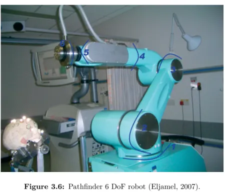
3.3.3 NeuRobot . . . 27 3.3.4 Evolution 1 . . . 29 3.3.5 NeuroArm . . . 30 3.3.6 Pathfinder . . . 31 3.3.7 Robocast . . . 32 3.3.8 Rosa . . . 33
3.4 Current Trends and Future Directions . . . 35
4 Learning about Robot-Assisted Stereotactic Neurosurgery 39 4.1 Learning in Simulation . . . 39
4.1.1 Kinematic Fundamentals . . . 41
4.1.2 Transformations . . . 46
4.2 Stereotactic Simulator for Education . . . 48
5 Registering the Robot to the Surgery Reference Frame 53 5.1 Registration in Robot-Assisted Neurosurgery . . . 53
5.2 Real Robot’s Calibration . . . 55
6 Real Robot Implementation 59 6.1 Setup Description . . . 59
6.1.1 Motoman MH5 Robot . . . 60
6.1.2 Custom End-Effectors . . . 62
6.2 Working with References Frames . . . 64
6.3 Communicating with the Robotic System . . . 66
6.3.1 Ethernet Server Function . . . 66
6.4 Control Architecture . . . 69
6.5 Control Application for Stereotactic Neurosurgery . . . 71
6.5.1 Communication . . . 71
6.5.2 Commands and Codes . . . 72
6.5.3 Coordinate Convention . . . 74
6.5.4 Utilities . . . 78
6.5.5 Guide User Interfaces . . . 78
7 Results 89
7.1 Procedure Execution . . . 89
7.2 Reaching the Selected Trajectories . . . 92
8 Conclusions 95 8.1 Summary and Discussion . . . 95
8.2 Future Work . . . 96
Bibliography 108 A Spatial Descriptions and Transformations 109 A.1 Descriptions: position, orientation, and frames. . . 109
A.2 Transformations: Rotations and Translations. . . 110
A.3 X-Y-Z fixed angles: Roll, Pitch, and Yaw. . . 111
A.4 Unit Quaternions. . . 113
B Students Questionnaire 117 C Least-Squares-based Registration Problem 119 C.1 Horn’s Method . . . 120
D Custom End-Effectors Drawings 125
List of Figures
2.1 Cartesian planes around the third ventricle (Gildenberg and Krauss, 2009). 7
2.2 (A) Talairach system, with the (B) mounted grid (Cardinale et al., 2012). . 8
2.3 The center-of-arc principle (from ELEKTA Leksell Online Manual). . . 9
2.4 BRW Stereotactic System (Arle, 2009). . . 9
2.5 Stereotactic reference system attached to the patient’s head. Mounting positions for the stereotactic frame are indicated in red. . . 12
2.6 Planned trajectories marked in violet (left), and blue (right). . . 13
2.7 Stereotactic coordinates for the chosen insertion trajectories. . . 14
2.8 Confirming the stereotactic frame settings. A: Phantom device; B: Stereo-tactic frame; C: Microdrive. Mechanical screws are marked in black. . . 15
2.9 Marking the entry position in the scalp. . . 15
2.10 Hole Drilling. . . 16
2.11 Inserting the electrodes. . . 16
2.12 Recording brain signals, given by the central electrode (green), anterior (red), posterior (yellow), medial (rose), and lateral (blue). . . 17
2.13 Confirming quadripolar macroelectrode placement (indicated by the white arrow). . . 17
3.1 NeuroMate robot (Renishaw, 2013). . . 25
3.2 Johns Hopkins University project setup (Haidegger et al., 2008b). . . 26
3.3 NeuRobot robotic arm (Auer et al., 2002). . . 28
3.4 Evolution 1 robotic system (Zimmermann et al., 2004). . . 29
3.5 NeuroArm surgical robot (Hall et al., 2010). . . 30
3.7 Robocast robotic arm: Gross positioner (GP), fine positioner (FP), and
linear actuator (LA), from right to left (Comparetti et al., 2011). . . . 33
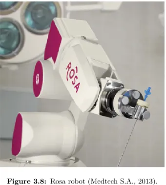
3.8 Rosa robot (Medtech S.A., 2013). . . 34
4.1 Simulation window showing the simulated robotic manipulators integrated in a neurosurgery operating room environment (Faria, 2012). . . 40
4.2 Motoman MH5 manipulator. . . 42
4.3 6 DoF manipulator (Faria, 2012). . . 44
4.4 Plane projection containing joint angles 2 and 3 (Faria, 2012) . . . 45
4.5 Robot’s base {B}, tip {T}, and end-effector {E}; and surgery {S} reference frames. . . 47
5.1 Recording holes coordinates. . . 56
6.1 Work scenario. . . 60
6.2 Robot’s working range in relation to a reference point p (YASKAWA Motoman). 61 6.3 Robotic system connections. From left to right is the programming pendant, the controller, and the manipulator. . . 61
6.4 Custom End-Effectors. . . 62
6.5 Tools defined at the programming pendant. . . 63
6.6 Type of coordinate spaces. . . 64
6.7 Defining the surgery coordinate system based on frame coordinates. . . 65
6.8 Host Control communication mode. . . . 66
6.9 Devices configuration. . . 67
6.10 Setting the [REMOTE] mode. . . 67
6.11 Command transmission using the Ethernet server function. . . 68
6.12 Communication process. . . 70
6.13 YARP message (Machado et al., 2012b). . . 70
6.14 Control Application basic architecture. . . 72
6.15 Defining target position and orientation. . . 75
6.16 Trajectory vector projection in the plane formed by the stereotactic ring. . 77
6.17 MainWindow user interface. . . 79
6.18 Coordinate System Selection question dialog. . . 80
6.20 ZDCoordinates user interface. . . 82
6.21 ZDTask user interface. . . 82
6.22 Allowing Robot Motion. . . 84
6.23 Robot home position. . . 86
6.24 Returning to home position. . . 86
6.25 Error Dialogs. . . 88
6.26 Warning the user that the robot is returning to a safe position. . . 88
7.1 Approaching the selected trajectory and adjustment of the robot tool orien-tation. . . 90
7.2 Assisted- drilling and electrode’s guidance. . . 91
7.3 Finishing the procedure - return to home position. . . 92
7.4 Draft of the selected trajectories coordinates. . . 92
7.5 Robot Postures when D = 45◦. . . 94
7.6 Robot Postures when D = 135◦. . . 94
7.7 Robot Postures when D = 90◦. . . 94
A.1 Locating an entity in position and orientation. . . 109
D.1 Pivot. . . 125
D.2 Tool Holder. . . 126
List of Tables
4.1 Denavit-Hartenberg parameters of the Motoman MH5 manipulator. . . 44 4.2 Simulator’s contribution in learning robotic concepts. . . 49
4.3 Relevance of using a specific neurosurgery task and scenario. . . 49 4.4 Students’ feedback based on the institutional survey. . . 50
4.5 Descriptive statistics of exam scores. . . 50
6.1 Motoman MH5 manipulator motion and speed limits. . . 62
E.1 Status-Read Commands. . . 129 E.2 Operation System Control Commands. . . 130
Nomenclature
AC Anterior Commissure.API Application Programming Interface.
BRW Brown-Roberts-Wells stereotactic system. CT Computed Tomography.
DALY Disability Adjusted Life Year. DBS Deep Brain Stimulation. DOF Degree of Freedom.
FDA Food and Drug Administration. GBD Global Burden of Disease. GPi Globus Pallidus Internus.
GUI Graphical User Interface. IPG Implanted Pulse Generator.
MCP Medial Coronal Plane.
MRI Magnetic Resonance Imaging. PC Posterior Commissure.
PD Parkinson’s Disease.
SEEG StereoElectroEncephaloGraphy. STN SubThalamic Nucleus.
VIM Ventral InterMediate nucleus of the thalamus. WHO World Health Organization.
Chapter 1
Introduction
1.1
Aim of the Dissertation
The aim of this dissertation is to contribute to the development of a robotic system able to assist neurosurgeons in the implantation of multi-electrodes directly within brain
structures thus allowing intracerebral signals recording (SEEG), and stimulation of deep brain structures (DBS), for symptomatic treatment of neurological disorders. The robotic
system should be able to hold and manipulate the required surgical instruments, aligning them according to pre-planned trajectories and medical team instructions, thus providing
the stability and precision needed when manipulating instruments directly within the brain. This MSc project continues the previous work done by Carlos Faria, who implemented
an initial solution in simulation (Faria, 2012). The challenge is to use the control code already developed in simulation to develop a control approach for a real robotic manipulator
for neurosurgery assistance. The main goal involves the development of a control application to interact with the robot’s controller, taking into account the task specifications, constraints
and safety procedures. Additionally we will developed a graphical user interface based on high-level commands better suited and more intuitive for the neurosurgeons (end-users).
1.2
Problem Statement and Motivation
Neurological disorders have always been a main concern of public health, and great efforts
have been made to manage the consequences and burden they bring to current societies. These are ones that affect the nervous system, causing motor and cognitive impairment in
people suffering from them, which greatly compromise their quality of life (World Health Organization [WHO], 2007).
In order to evaluate the burden caused by neurological disorders in current societies, several studies have been conducted by organizations and institutions around the world.
The purpose is to increase professional and public awareness of the burden associated with neurological disorders, and to point out the need to provide the best possible care to people
who suffer from them.
According to results of World Health Organization (2006), the burden associated with
these disorders is tremendous, which affects entirely societies, namely patients, families, and caregivers. The collaborative study, known as the Global Burden of Disease (GBD),
leaded by WHO, the World Bank and the Harvard School of Public Health, presents projections of the global burden of neurological disorders in terms of DALY (abbreviation
of Disability-Adjusted Life Year) expressed as the number of years lost due to disability or premature death. The GBD study predicts a total global burden rise over the next years (consult table 2.4. of GBD (Dua et al., 2006)). According to these results, Epilepsy
and Parkinson’s disease together accounts for a number of approximately 9 million DALYs in 2015, which is expected to ascend 3% by 2030. This rise can be explained by the
expected increase in the prevalence of neurological disorders, as a result of extension of life expectancy and global population aging.
Associated direct and indirect costs that such disorders bring to the society, complement the estimates of the burden they cause. According to Olesen et al. (2012), in 2010 the
European costs due to Epilepsy and Parkinson’s disease was estimated as, approximately, 28 billion Euros, 3.5% of the total European costs of brain disorders, i.e. neurological and
mental disorders, included in the study.
These facts bring great challenges to current societies. In order to overcome the burden
they cause, prevention and the pursuit for the best possible care worldwide is required. For this purpose, improvements and development of new efficient solutions are then welcome.
Advances in technology have made it possible for patients suffering from neurological disorders to receive effective treatment. Implantation of deep brain electrodes for DBS is
currently a well-established form of therapy for symptomatic relief of neurological disorders, such as Parkinson’s disease (Benabid et al., 2009). To take the best results of this procedure,
of the surgeon and his team is then required during surgery, which turns out to be an extremely demanding intervention, both cognitively and also physically, as the surgical
procedure lasts for long periods of time. With the increasing number of cases assigned for surgical treatment, and time demanding and exhausting characteristics of the procedure,
effective treatment can not be performed at a necessary pace (Ostrem, 2010).
Robotic assistance in procedures such as DBS turns the procedure less physically
and cognitively demanding for the surgeon and medical team, as robots can take over menial tasks like holding, and placing surgical instrumentation, namely for skull drilling
and implantation of multiple electrodes. This significantly improves the overall procedure, as it joins the advantages of a robotic system in terms of precision and steadiness (essential
in these type of procedures), and the surgeon’s capabilities namely his/her surgical skills and judgment ability, based on his/her experience.
Another common example which benefits of robotic assistance is SEEG, used to measure brain activity directly within brain structures to identify the epileptogenic region, in epileptic patients (Cardinale et al., 2013). The swiftness and flexibility of a robotic
system in precisely reach the electrodes insertion trajectories is even more significant in this type of procedure, given the high number of electrodes placed - up to 12-14 electrodes
(Cardinale et al., 2012).
1.3
Structure of the Thesis
In addition to this Introduction chapter, the present dissertation is structure as follows. In Chapter 2, we introduce the concept of stereotactic neurosurgery, and describe a
typical DBS procedure for further analysis of the advantages of including robotize systems as assistive tools in such procedures.
In Chapter 3, we start by defining a robotic manipulator, and presenting the role of robotic systems in surgery. We elaborate a state of the art review of robot approaches for
stereotactic neurosurgery assistance, evidencing their main characteristics, strengths, and weaknesses. Finally, sought characteristics of a robotic system for stereotactic neurosurgery
are depicted.
In Chapter 4, fundamental concepts of robotics are presented, including concepts
and formulation of robot kinematics and spatial representations and transformations of reference frames. An experiential learning project of such concepts based on a simulation
tool developed by our group, designed to resemble a robot-assisted stereotactic brain surgery, is presented and described in this chapter. The impact of the simulator in teaching
students of robotics is analyzed.
Chapter 5 introduces the concept of registering different reference frames, and analyzes the problem of registration in the paradigm of image-guided surgery procedures assisted by robotic devices. The calibration process for registering the robot’s with the
surgery reference frame from sets of measured points obtained in both coordinate systems is presented and described.
In Chapter 6, we present the work developed using a real robotic device. The designed system’s control architecture is presented and described in this chapter. We
also present the developed control application and all its embedded features, including fundamental safety mechanisms.
In Chapter 7, there are presented the results regarding the developed control appli-cation. We also assess the robot’s ability to reach surgical trajectories.
Chapter 2
Stereotactic and Functional
Neurosurgery
The great impact of neurological disorders in society has brought the need to seek constant
improvements in treatment or methods used to treat those disorders. Functional neuro-surgery is performed when common methods or treatment using conventional drugs show no
effectiveness. Deep Brain Stimulation (DBS) has been proving its success in mitigating the symptoms caused by neurological disorders. Additionally, Stereoelectroencephalography
(SEEG), other common type of stereotactic procedure, provides essential information in cases of drug-resistant epilepsy, by invasively access the epileptogenic zone in epileptic patients.
This chapter introduces the concept of stereotactic neurosurgery, and presents the steps involved in a typical stereotactic brain surgery procedure - a functional neurosurgery
for DBS - in order to further analyze the advantages of including a robotic system for assistance on those procedures.
2.1
Stereotactic Neurosurgery
Stereotactic neurosurgery, or simply stereotaxy, is a surgical technique that makes use of a
three-dimensional coordinate system to locate and access certain targets inside the brain without direct visualization of those targets (Kandel, 1989; Gildenberg and Krauss, 2009).
It includes the use of an apparatus to direct and guide a determined surgical instrument, such as a cannula, electrode or other type of probe or device, to a certain structure or area
within the brain (the target) through a small burr hole in the skull (Gildenberg, 1988). The use of this technique open doors to minimal invasive surgery procedures (Chen and Apuzzo,
2003), such as: biopsies, radiosurgery, lesion aspiration; and also functional stereotactic procedures based on destructive or augmentative methods (e.g. Deep Brain Stimulation).
Before stereotactic surgery, most deep brain targets were off limits to the surgeon, as well as others that could not be accessed without great risks to the patient. The advent
of stereotactic procedures made it possible to safely and accurately access most of those targets (Gildenberg, 2013). To guide the surgeon in his approach, this technique uses
stereotactic frames firmly attached to the patient’s head.
To better understand the principles of stereotaxy, a description of several approaches
of apparatus - stereotactic frames - for neurosurgery, and how they have been evolving over the years, is made based on the following textbooks (Lozano et al., 2009; Gandhi and
Schulder, 2003; Lunsford, 1988).
2.1.1 Stereotactic Apparatus
In the early 1900s, stereotactic apparatus started to be reported. By that time, Horsley and
Clarke introduced their first device for stereotaxy to access desired areas or structures within the brain of monkeys (Horsley and Clarke, 1908). They specified the use of a Cartesian
coordinate system that made it possible to define points in space from the intersection of 3 orthogonal planes: an anterior-posterior, a lateral and a vertical planes. Horsley and
Clarke used skull landmarks and constructed a standard brain atlas of monkeys, in order to define the desired targets within the brain according to those landmarks. Registration
of those to the position (location) of the head was performed by relating them to the same parts of the device that securely held the head. Horsley and Clarke research remained the
hallmark of stereotactic systems.
It was only later, that the first apparatus for use in human stereotaxy was reported
by Spiegel et al. (1947). Spiegel and his partner Wycis combined the use of a stereotactic device similar to Horsley and Clarke’s, X-ray imaging, and a human brain atlas. The
great improvement was undoubtedly the use of X-ray imaging to identify specific anatomic landmarks within the brain, in order to obtain the location of a certain target in relation
to those landmarks. Here, the identification of intracerebral landmarks was of extremely importance, since the Horsley and Clarke’s method of using skull landmarks is unreliable
for humans, due to the great variability in the shape of the human skull. Spiegel and Wycis therefore selected intracerebral landmarks around the third ventricle, from which the
three coordinates could be measured, each of which based on one of the three Cartesian planes, previously defined by Horsley and Clarke (Figure 2.1). The use of anterior and
posterior commissures, later defined by Talairach and his colleagues as standard anatomical landmarks (Talairach and Tournoux, 1988), has been adopted by most neurosurgeons
performing stereotactic procedures to the brain.
Figure 2.1: Cartesian planes around the third ventricle (Gildenberg and Krauss, 2009).
Since Spiegel and Wycis work, a variety of apparatus were rapidly introduced, and
around 1950’s over 40 different devices for stereotaxy (stereotacic frames) had already been designed and reported (Gildenberg and Krauss, 2009).
Gildenberg (1988) listed four different categories of stereotactic apparatus: (i) transla-tional systems, (ii) burr-hole mounted, (iii) arc-centered, and (iv) systems with interlocking
arcs. As the name implies, translational systems allow only translational not angular adjustments. In the original Horsley and Clarke’s translation system, the determined
surgical instrument moves vertically along a system of slides in two dimensions, and a microdrive is used for lowering the electrode to the target. The Talairach system, a today’s
commonly used stereotactic device, is another example of a translational system in which instruments are inserted to a measured depth through coaxial holes in a mounted grid
(Figure 2.2). This system does not allow much flexibility in instrument insertion, however
Figure 2.2: (A) Talairach system, with the (B) mounted grid (Cardinale et al., 2012).
it is particular important as it allows the introduction of an array of instruments, such as
electrodes, particularly useful to explore a determined area for location of epileptogenic activity, in SEEG procedures (Cardinale et al., 2012).
In burr-hole mounted systems the instrument used to guide the probes is actually attached to a fixed burr hole (or entry point), providing a limited range of possible target
points using that specific entry point. These systems provide only angular adjustments in aligning the electrode to a specific target point. This type of systems can lead to great
inaccuracies and because of that fact they have not been adopted to perform stereotactic procedures.
Arc-centered systems were first introduced by Lars Leksell who designed the first arc centered device in 1948, (Leksell and Lunsford, 1988; Lunsford et al., 2009). This type of
systems use a semicircular arc and a probe holder mounted on that arc, being the probe pointed at all times (along any angle) to the center of the arc (Figure 2.3). In Leksell’s
system, the center of the arc is aligned with and corresponds to the target. Contrarily, in other systems, such as the Todd and Wells arc system, this is fixed and it is the patient’s
head that moves to align the target, so that the target point lies at the center of the apparatus (Arle, 2009).
Brown-Roberts-Wells (BRW) apparatus represents the systems that use interlocking arcs to point a certain probe to the target (Apuzzo and Fredericks, 1988; Arle, 2009). It
consists of a skull base ring and three interlinked arcs, providing an infinite number of entry points from which the target can be reached by that certain surgical instrument.
Figure 2.3: The center-of-arc principle (from ELEKTA Leksell Online Manual).
This system is adjusted by moving four rotational settings (Figure 2.4a), so that the probe
holder is aligned with a determined trajectory formed by a specified entry and target point. A N-localizer unit consisting of six vertical and three diagonal rods (Figure 2.4b)
is attached to the system for CT or MRI-image guided stereotactic surgery. In addition,
(a) BRW Rotation Angles. (b)BRW N-localizer unit and fiducials.
Figure 2.4: BRW Stereotactic System (Arle, 2009).
this system also includes a phantom base onto which the stereotactic frame is placed to
test the accuracy of its settings. The complex determination of its settings is the main disadvantage of this system.
Besides the previous mentioned stereotactic frames, many others have been introduced. Notwithstanding some variations between them, all have the common goal to provide a
reliable reference system, establishing a rigid relationship between the patient’s head and the outer space where instruments are handled, for localization and approach of the target
within the brain (Sharan and Andrews, 2003).
Today’s neurosurgery still relies on stereotactic frames developed almost half a century
ago. However, these systems are often held as cumbersome and inflexible devices, often uncomfortable to the patient, and with limitations in reaching insertion trajectories. In
addition, these are set through mechanical screws whose precision is limited by the human vision.
The introduction of robotic systems in neurosurgery, combined with current high-resolution imaging, greatly improve the methodology and workflow of stereotactic
neuro-surgical procedures (Cardinale et al., 2013). It brings much more versatility and flexibility in trajectory selection than stereotactic frames, besides the higher accuracy, precision,
and steadiness of surgical instruments manipulation. Also with these systems the surgery plan can be directly transferred to the robotic controller, avoiding manual manipulation of
information, therefore reducing human errors.
For a complete understanding of stereotactic neurosurgery, and how can a robotic system improve the working conditions, a description of a typical stereotactic brain
surgery procedure is made in the next section, regarding the tasks and workflow followed, and instrumentation used along the surgical procedure, more specifically in a functional
neurosurgery for DBS. This will be fundamental to realize when and how can a robotic manipulator be of use, understanding which tasks the robot is expected to perform within
the operating room.
2.2
Functional Neurosurgery - Deep Brain Stimulation
Access to deep brain targets with the purpose to alter the abnormal function of the brain -functional neurosurgery - for symptomatic treatment of movement disorders, represents
the earliest indications for stereotaxy (Chen and Apuzzo, 2003).
The technique - Deep Brain Stimulation (DBS) - used in functional neurosurgery,
involves stereotactic implantation of electrodes directly within brain structures; and the implantation of a neurostimulator, also called Implanted Pulse Generator (IPG), typically
placed in the subclavicular region (Benabid et al., 2009; Marks Jr., 2010; Machado et al., 2012a). To connect the electrodes to the IPG, extension wires are used so that electrical
impulses are sent from the IPG to the determined target.
less invasive or conventional drug therapies (Ostrem, 2010). It is currently approved by the US Food and Drug Administration (FDA) for treatment of Parkinson’s disease (PD),
essential tremor, and dystonia (Machado et al., 2012a), and has also been target of various research studies for treatment of chronic pain, epilepsy, and psychiatric disorders such as
Tourette’s syndrome, (Rasche et al., 2006; Goldman, 2010; Porta et al., 2012).
The growing acceptance of DBS, and choice among other therapies such as ablative
surgery, is greatly due to its non-destructive and reversible characteristics. Stimulation parameters are set non-invasively, and includes adjustments in amplitude, width, and rate
of the electrical pulse, taking into account the maximization of symptomatic relief while minimizing the adverse effects (Zauber et al., 2010; Erwin B. Montgomery Jr., 2010). The
side effects related to stimulation programming can be easily reverted, by adjusting the stimulation parameters.
Main targets of DBS procedures includes the ventralis intermedius (VIM) nucleus of the thalamus for essential tremor, globus pallidus (GPi) for dystonia, and the subthalamic nucleus (STN) for PD (cf. table 1.1. of Marks Jr. (2010)). Neurostimulation principles and
its effects are not the focus of this project and therefore they will not be further analyzed in this dissertation. Further information on neurostimulation principles can be consulted
in the following (Erwin B. Montgomery Jr., 2010).
Contrarily, the way to get an accurate, and precise targeting and safe approach of
the correct site within the brain is the main focus of this dissertation, which is likewise important in order to obtain optimal clinical outcomes. By guaranteeing precise targeting,
and ensuring the ideal stimulation parameters, deep stimulation efficiently disrupts the abnormal brain function caused by neurological disorders, reducing the severity of their
symptoms, which results in significant improvements of patient’s quality of life (Benabid et al., 2009).
In order to acquire practical insight about the surgical procedure workflow, we assisted to a DBS surgery that took place in the Service of Neurosurgery at Coimbra Hospitals and
University Center. It will be henceforth described a bilateral DBS surgery, conducted in a patient suffering from Parkinson’s disease.
Succinctly, it involves preoperative MRI and CT scanning of the patient’s brain for target identification and location with respect to the stereotactic system of reference,
a phantom device; scalp incision and accession of the intracranial cavity by drilling a burr hole in the skull; intraoperative micro/macroelectrode recording/stimulation, and
assessment of patient improvements; and, finally, implantation of the definite quadripolar macroelectrode upon selecting the ideal stimulation parameters; (postoperative set of
stimulation parameters).
2.2.1 Preoperative Targeting and Patient Preparation
Days before surgery, the patient undergoes a MRI scan in order for the neurosurgeon and
his team to identify and locate the target for electrode implantation - the subthalamic nucleus (STN).
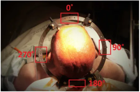
In the day of the surgery, the patient’s head is shaved and prepared with betadine, in order to prevent infections; and the reference system - stereotactic head ring - is carefully
attached to the patient’s head, under local anesthesia, by using four pins screws tightened to the patient’s skull (Figure 2.5).
Figure 2.5: Stereotactic reference system attached to the patient’s head. Mounting positions for the stereotactic frame are indicated in red.
The facility uses the Zamorano-Dujovny (ZD) localizing system (INOMED,
Emmendin-gen, Germany), a system based on the center-of-arc principle (cf. subsection 2.1.1), which establishes a Cartesian coordinate system with origin located at the center of the
stereo-tactic head ring. A localizer arc - stereostereo-tactic frame - is mounted in any one of the four positions on the stereotactic ring (0◦, 90◦, 180◦, and 270◦ - shown in Figure 2.5). The
arc frame imply three linear, and two angular adjustments. The three linear adjustments (scaled A, B, and C) correspond to the X, Y, and Z axes. The Z-axis always corresponds
to scale C, while the allocation of the other coordinate axes (X and Y) depends on the location of the stereotactic frame on the head ring. The two angular adjustments (D, and
E) define the trajectory of the probe.
With the stereotactic reference system firmly attached, reference fiducials are fixed to
the system, and a CT imaging scan is performed.
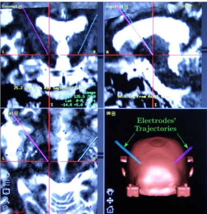
The results obtained from both MRI and stereotactic CT scans are matched using a
specialized imaging planning software that fuses them in 3D space with high precision. This allows to locate the target in relation to the reference fiducials, and to plan the trajectories
of electrodes towards the target that avoid major blood vessels or other potentially harmful structures (Figure 2.6).
Figure 2.6: Planned trajectories marked in violet (left), and blue (right).
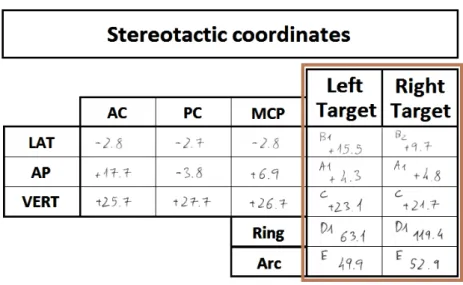
In the present intervention, the anterior and the posterior commissures (AC-PC) were used as anatomical landmarks for atlas-based indirect targeting. Target coordinates were
obtain in relation to the AC-PC line, and thereafter converted in stereotactic coordinates, i.e. in relation to the surgical frame of reference (Figure 2.7).
Figure 2.7: Stereotactic coordinates for the chosen insertion trajectories.
The coordinates obtained are regarded as an initial target, as it may not be spotted
where the stimulation will produce the optimal symptomatic relief, which may be slightly changed during intraoperative.
2.2.2 Intraoperative
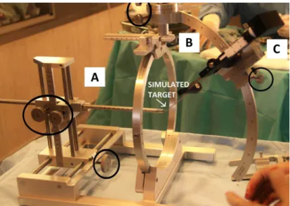
Intraoperatively, the sterotactic coordinates obtained from preoperative planning are confirmed using a phantom device (Figure 2.8A). This phantom device simulates the target
coordinates to be achieved by the tip of the electrode. It includes a stereotactic ring, which simulates the head ring attached to the patient’s skull, that establish the system of
reference.
The stereotactic frame, mounted at the 0◦position of the stereotactic ring (Figure 2.8B), includes a driver (Figure 2.8C) responsible of lowering the electrodes, along the desired trajectory, to the pre-determined target.
At this point, the stereotactic target coordinates (X, Y and Z) are set at the phantom device, and stereotactic frame. In this case - frame mounted at 0◦ - the scale A of the stereotactic frame corresponds to the Y-axis, and the scale B to the X-axis. Scale D and E, representing the rotation along the Y- and X- axes, respectively, are also set at the
stereotactic frame. At the end, it is expected that the probe tip and the tip of the phantom device (simulating the target) are coincident.
Each coordinate is set using mechanical screws, either at the phantom device and stereotactic frame (see Figure 2.8), and confirmed via a millimetric scale engraved between
Figure 2.8: Confirming the stereotactic frame settings. A: Phantom device; B: Stereotactic frame; C: Microdrive. Mechanical screws are marked in black.
moving components, being its precision directly dependent on human vision.
After this process, the calibrated stereotactic frame (along with the driver) is
dis-mounted from the phantom device, and dis-mounted on the stereotactic ring already attached to the patient’s head. A thin straight metal rod is placed along the driver to mark the
entry position in the patient’s scalp (Figure 2.9). The frame is moved away to make the scalp incision, and to drill the burr hole in the skull (Figure 2.10), to access the intracranial
cavity of the patient for electrodes insertion.
Figure 2.9: Marking the entry position in the scalp.
The stereotactic frame is putted back in place, along with the driver to guide the
electrodes (and cannulas) collinear to the selected trajectory.
(a) Drilling the burr hole. (b)Burr hole.
Figure 2.10: Hole Drilling.
other are inserted into the patient’s brain, using the driver, in order to cover a larger area to increase the probability to find the optimal stimulation site (Figure 2.11). According to
Figure 2.11: Inserting the electrodes.
their insertion position, they are labeled as central (set along the pre-planned trajectory), anterior, posterior, medial, and lateral.
The microelectrodes records cortical electrical signals, and are inserted in order to determine the precise area of the brain to be stimulated. First, they are positioned 15 mm
above the target, then inserted through an iterative process depending on the distance to the target. They are lowered millimeter by millimeter until 5 mm, and then half a
millimeter up to the target. In each iteration the neurophysiological readings of each microelectrode (represented by different colors in the recording system, Figure 2.12) are
saved, compared and analyzed. As the electrodes approach the target, an augment of neuronal activity is expected, due to the verified hyperactivity of the subthalamic nucleus
Figure 2.12: Recording brain signals, given by the central electrode (green), anterior (red), posterior (yellow), medial (rose), and lateral (blue).
in patients suffering from Parkinson’s disease.
Thereafter, stimulating macroelectrodes are set where the electrodes retrieve an
electrophysiological record closer to the expected. Following again an iterative methodology, patient’s symptoms are evaluated according to electrode depth or stimulus amplitude
adjustments, seeking for the best response which avoids side effects. At this stage the patient is kept awake for the best evaluation of results.
Finally, when the ideal electrode’s placement and stimulation parameters are found,
the micro/macroelectrodes are replaced by the definitive quadripolar macroelectrode (Figure 2.13), that should be later connected to the IPG (implanted under general anesthesia,
either at the end of the surgery or several days later). Only days to weeks after implantation, stimulation is activated.
Since the present intervention was a bilateral procedure, all intraoperative process was repeated for the other side of the brain. The all procedure took about 12 hours to be
performed, since preoperative.
2.2.3 Steps towards a Successful Stereotactic Brain Surgery Procedure
For a successful stereotactic surgical procedure, such as DBS, with minimum risks to the patient, it is of extremely importance that the implantation of the electrodes would be
uncomplicated, steady, accurate and precise into the determined target, for stimulation of the correct site in order to achieve the best results. It is also important to avoid areas
of the brain that could harm the patient, compromising patient outcomes. It is therefore essential an evaluation of the methods and instrumentation used when inserting electrodes
directly within brain structures.
Current problems of the traditional DBS workflow, mainly related with the
instrumen-tation (stereotactic frames) used to reach selected trajectories for electrodes insertion, may refer to:
• manual handling of information - that can lead to errors during data transmission
(e.g. setting the frame stereotactic coordinates according to the preoperative data).
• human setting of the stereotactic frame parameters - which is totally dependent on
human vision, and regulated by mechanical screws.
• the slow and repetitive process of setting the frame stereotactic coordinates and
mounting/dismounting this from the stereotactic ring.
• constraints imposed by the stereotactic frame in reaching eccentric trajectories for
electrodes insertion.
• restriction to a unique task - insertion of electrodes.
As stated previously, a typical stereotactic surgery (as the one previously described) lasts for long periods of time, and problems like the ones referred, in some way, may
contribute to this lag. These problems aggravate in procedures such as SEEG where the number of electrodes placed to record brain activity is elevated - 12 to 14 electrodes.
Besides the time expended in setting the stereotactic frame coordinates for each selected electrode insertion trajectory, the search for a device that could allow neurosurgeons to
insert electrodes in eccentric trajectories without the constraints imposed by stereotactic frames is even more significant in this type of procedure. Contrarily to DBS in which the
interest is focus on the deep brain target, and the entry point can be changed pivoting around it, in SEEG procedures it is not just the target but the whole trajectory that
matters, and therefore this can not be lightly changed.
Due to the characteristics of surgical procedures of this kind, these turns out to be
extremely demanding procedures for neurosurgeons and medical team. Improvements that could reduce the effort expended by the surgeon, and improve the overall flow of the
procedure could then be very helpful.
Next chapter introduces the use of robotic systems in neurosurgery, evidencing the role
they play in surgical procedures of this type. For now, we advance with some highlights of how can a robotic system improve the working conditions, and contribute to the overall
success of stereotactic surgical procedures. Besides the improved precision, it:
• enables the surgical information to be managed between the planning software and
the robot controller, therefore avoiding data loss during the process.
• allows the neurosurgeon to remain entirely focus on the task being performed along
the predetermined trajectory, which is set by the robot, therefore reducing the risk
of human errors.
• avoids the slow and repetitive process of mounting/dismounting the stereotactic
frame and manual setting of frame coordinates for each electrode insertion trajectory.
Selected trajectories can be easily reached by the robot, simply interacting with its graphic interface, which aids the neurosurgeon on that task.
• can reach eccentric electrode insertion trajectories, overcoming the constraints of
stereotactic frames.
• can handle other surgical instrumentation, and so accomplish other tasks. For
instance it can help the surgeon in drilling the burr hole in the skull, constraining
the task to be carried specifically along the predefined path, instead of executing it based on a marked entry position.
Chapter 3
Robotic Systems and
Stereotactatic Neurosurgery
Over the past years, neurosurgical procedures have undergone significant changes. Nathoo
et al. (2005) stated "soon the scale of surgery will become so small that even the most skilled surgeon will reach the limit of his or her dexterity". The introduction of robotic
systems in surgery has emerged as a valid option to overcome those limits. Rather than replace the surgeon, surgical robots are currently being used to extend or enhance human
capabilities, providing assistance in performing several different tasks within the operating room, always under ultimate control of the surgeon (Vittiello et al., 2012).
So far, several reviews on robotic systems describing their role in neurosurgical
procedures and suggesting its promising future in this field have been published (Nathoo et al., 2005; Haidegger et al., 2008a; Zamorano et al., 2004; Karas and Chiocca, 2007;
McBeth et al., 2004; Eljamel, 2008; Karas and Baig, 2008).
This chapter starts by defining a robotic manipulator, and presenting the role of robot
devices in an operating room. State of the art robotic systems are presented, evidencing their main characteristics, strengths, and weaknesses. At the end, it makes an analysis of
the sought characteristics of a robotic system towards stereotactic neurosurgery.
3.1
Robotic Manipulator: A Definition
A robotic manipulator was defined by Robot Institute of America, in 1979, as: "A re-programmable, multifunctional manipulator designed to move material, parts, tools, or
specialized devices through various programmed motions for the performance of a variety of tasks". Basically, it consists of a set of one or more kinematic chains, composed by rigid
bodies (links), connected through articulated joints (Craig, 1989). It may resemble a human arm (composed by shoulder, elbow, wrist), allowing the manipulator to be positioned in a
variety of ways in its workspace.
Angeles (2003) divided robotic systems architecture into five subsystems: (i) a
mechan-ical subsystem; (ii) a sensing subsystem; (iii) an actuation subsystem; (iv) a controller; and (v) an information-processing subsystem. According to its kinematic chain architecture,
robotic manipulators can be classified as: serial manipulators which have an open kinematic chain, i.e. there is only one path from one end (the base) to the other (the end-effector) of
the robotic chain; or parallel manipulators which have a closed kinematic chain (Ceccarelli and Ottaviano, 2008). The robot’s end-effector usually refers to an instrument that is
attached to the manipulator’s last link and used to perform a certain task.
The sensing subsystem (composed by the robotic system sensors) detects information from the environment and the robot itself, providing information about the location of the
robot with respect to the environment. In its turn, the actuation subsystem (composed by actuators) converts energy into motion, therefore supplying power to joints, responsible of
moving each link so that the robot can reach a desired position and orientation.
The robot control unit, formed by the controller device and the information processing
system, basically acts as the "brain" of the robotic system, being able to assimilate and to process the input data received either by the sensors or the control algorithms, therefore
controlling the information sent to each actuator (Jazar, 2010).
Some concepts will be mentioned when referring the desirable characteristics of robotic
manipulators. Common parameters that categorize robotic manipulators may refer to: the number of degrees of freedom, its working space, precision, and repeatability. The
number of degrees of freedom (DoFs) defines the number of independent motions that can be performed by a robotic manipulator, and equals to the number of joints in case
of serial manipulators. Its working space refers to the space that can be reached by the manipulator’s end-effector which obviously depends on the dimension of its links, and also
the limits of its joints’ angles (Craig, 1989; Jazar, 2010). Finally, precision refers to the ability of the robot to position its end-effector at a certain position within its workspace,
same position previously set.
3.2
Robotic Assistance in Surgery
Surgical robots can be classified according to the role they play within the operating
room (Haidegger et al., 2008a), as: passive, in which the surgeon exerts direct control over the robot that mainly serves as a tool holding device; semi-active, where the robot
performs the operation although under direct human control; or active, in which the robot performs automatically certain interventions, with no direct control of the surgeon (only if
necessary).
Within the operating room, surgical robots are also classified according to their
interaction with the system end-users (Nathoo et al., 2005), as: supervisory-controlled robotic systems, in which the surgeon plans the operation, sends the information to the
robot which, in its turn, autonomously moves under surgeon’s supervision; telesurgical systems, in which the surgical robot (slave) replicates the surgeon’s hands movements
which uses a (master) joystick-type device to exert direct control over the robotic system; and shared-control systems, where both the surgeon and the robot cooperatively share the
control of the surgical tool. In this last, the surgeon, who is still in charge of the operation, takes advantage of the robot as a steady-hand manipulator that usually exerts a smooth,
tremor-free precise positional control and force scaling.
Major advantages of robotic systems in surgery starts by their ability to process and
to use large amounts of information to perform identical and repetitive tasks with good stability and precision, during long periods of time. On the other hand, surgeons are
superior in combining diverse sources of qualitative information to make good judgments, based on their experience. Surgeons also have a strong hand-eye coordination, and a
powerful sense of touch. However, humans are susceptible to fatigue, which may lead to an extension of the operating time, increasing the costs and the chance for human errors.
The cooperation between both humans and robots seems to contribute to the overall success of surgical procedures, specially in procedures in which the surgeon operates at a
very small scale (microsurgery) or through very limited access such as in minimally invasive surgery procedures, since it is possible to take advantage of both (Eljamel, 2008; Zamorano
et al., 2004). The differences encountered between humans and robots imply current surgical robots to perform only restricted tasks, following commands and instructions of
the surgeon and medical team.
To better understand the benefits and technical challenges of robot-assisted surgery,
next section provides a detailed overview of robotic surgical systems for use in stereotactic neurosurgical procedures.
3.3
State of the Art Robotic Systems
During the past decades, several approaches of robotic systems for neurosurgery have been
emerging, since their first application in this field, in 1985.
Initial experiments in neurosurgical robotics consisted of adaptations of industrial
robots that already existed at that time (Zamorano et al., 2004). In fact, the first robot used in neurosurgery, introduced by Kwoh et al. (1988), was the industrial PUMA robot
(Advances Research & Robotics, Oxford, CT), used to define the desired trajectory for probe insertion in a brain tumor biopsy procedure. With the identification of the target
using CT images, the task of the robot was to position the biopsy needle so that the surgeon could move it according to the planned trajectory. Although promising, due to
safety protocols that did not consent industrial robots to operate with people, this project was discontinued (Nathoo et al., 2005). However, major robotic systems that have been
brought to stage are based on this concept of positioning a determined surgical instrument, according to a planned trajectory.
For the purposes of this dissertation, next will be mentioned and described major robotic systems that were designed to assist neurosurgeons in performing fundamental
tasks within the operating room.
3.3.1 NeuroMate
In 1987, it was introduced for the first time the NeuroMate robot (Benabid et al., 1987). NeuroMate is an image-guided, robotic assistive system specifically design for stereotactic
neurosurgical procedures, originally developed at Grenoble University, France. It became the first neuro-robotic system to be approved by FDA, as well as the first to be
commer-cially available, in 1997. Bought and commercialized by Integrated Surgical Systems Inc. (Sacramento, CA, USA), it was later acquired by Shaerer Mayfield NeuroMate Sarl (Lyon,
France). Currently it is owned by Renishaw (Figure 3.1).
Figure 3.1: NeuroMate robot (Renishaw, 2013).
with an accuracy of 0.7 mm, and a repeatability of 0.15 mm, guaranteeing a payload stability of 7 kg (Varma and Eldridge, 2006). This system is able to work with CT, MRI,
and angiography images. The images obtained are processed by a kinematic positioning software system (VoXimTM, IVS Software Engineering) that allows 3D visualization of anatomical structures and brain targets, and precise image-based planning, including trajectory planning. NeuroMate uses either conventional stereotactic head frames, or a
frameless ultrasound registration system which reduces patient trauma. The last includes an implantable base that allows the insertion of a helicopter-shaped ultrasonic localizing
device used for registration of the robot’s position with the patient’s skull.
Li et al. (2002) results have shown that the application accuracy of NeuroMate’s
frame-based configuration is comparable to a standard frame-based or infrared tracked localizer systems. In this study, frameless configuration scored the worst precision, however
it still showed an acceptable standard value of 2 mm. In fact, Varma and Eldridge (2006) have shown that NeuroMate robot used in a frameless configuration achieved sufficient
accuracy to perform a set of neurosurgical procedures, such as movement disorder surgery. According to developers, NeuroMate provides a platform solution for a broad range of
functional neurosurgical procedures. In fact, it has been used in thousands of stereotactic electrode implantation procedures such as DBS, and SEEG (Varma and Eldridge, 2006;
Cardinale et al., 2013). Within the operating room, the NeuroMate robot works as a passive assistant, holding, supporting and stabilizing the instrumentation controlled by the
surgeon, which increases its safety. This system ensures precise spatial positioning of the instrument holder or tool guide, thereby reducing potential human errors.
On the other hand, it has its limitations, such as the cumbersome structure that connects the stereotactic device attached to the patient’s head to the robot, used to
establish the rigid relationship between the two, which highly limits the surgeon’s workspace. Furthermore, according to neurosurgeons, one of the desired upgrades for NeuroMate would
be to endow the robot with drilling capabilities (Cardinale et al., 2013).
To the best of our knowledge, we present a project of Johns Hopkins University (JHU),
which includes a modified NeuroMate surgical robot (Haidegger et al., 2008a,b). A 6 DOF force sensor is attached to its last link, and its end-effector is a high-speed bone drilling
surgical instrument. In this approach, both the surgeon and the robot cooperatively share the control of the surgical tool, which is based on force sensor readings.
Figure 3.2 shows fundamental components of JHU project setup. Beyond the modified NeuroMate robot, it includes a widely used navigation system - StealthStation (Medtronic Navigation, Louisville, CO) - its respective camera, and 3D Slicer open source software for
image visualization and planning. With this StealthStation camera system it is possible
Figure 3.2: Johns Hopkins University project setup (Haidegger et al., 2008b).
to locate desired elements in present setup. Optical tracking is made possible locating
passive markers (fiducials) mounted on the robot and on the patient or head clamp. This is important as it allows to know their position related to each other and with the system,