A biophysical
approach to
mitochondrial gene
therapy: gemini
surfactant-based
colloidal vectors
Ricardo de Sá Bessa
Mestrado em Bioquimica
Departamento de Química e Bioquímica 2016
Orientador
Prof. Doutor Eduardo Jorge Figueira Marques, DQB, FCUP
Coorientadora
Profª. Doutora Maria Amália da Silva Jurado, Dep. Ciências da Vida, FCTUC e CNC- Centro de Neurociências e Biologia Celular, Universidade de Coimbra
Todas as correções determinadas pelo júri, e só essas, foram efetuadas. O Presidente do Júri,
ACKNOWLEDGEMENTS
To my supervisor, Prof. Eduardo Marques for the opportunity to participate in the research group for this project, all the support given throughout the entire project and especially for the help in professional development.
To my co-supervisor, Prof. Amália Jurado, for the patience, knowledge and help on the biological part of the project.
To Prof. Luisa do Vale for the use of the synthesis laboratory and all the support and teachings.
To Dr. Ana Cardoso for always being there, and the help and teachings in laboratory work.
To all the physical chemistry research group for the friendship and companionship, through the year.
To Bárbara Claro for all the moral support and incentive.
To Isabel Oliveira and Bárbara Abreu for all their help and suggestions.
To my mother, for all the support, food and taxi services.
To my family, which accompanied me through this journey.
To José Ferreira, my co-conspirator in writing.
Abstract
Efficient mitochondrial gene delivery is a technique with great biomedical potential, due to the possibility of using it for the treatment of many pathologies, currently without cure. Among many other types of vectors, surfactant and lipid-based systems stand out as an efficient, safe and biocompatible strategy to integrate new DNA in the existing mitochondrial genome.
The aim of this work was to determine the physicochemical properties, transfection efficiency and cytotoxicity of novel serine-based gemini surfactants. Gemini are a class of surfactants containing two polar head groups and two hydrocarbon chains (n) linked by a spacer (s) at the headgroup level.
In this work, a series of four different serine-based gemini surfactants, all with a 12 carbon long alkyl spacer (n-12-n), and hydrocarbon chains containing n = 12, 14, 16 and 18 carbons, were successfully synthesized. The critical micelle concentration and other interfacial parameters of these compounds were determined by tensiometry, and several unusual and interesting trends were obtained.
These novel gemini surfactants were further used to prepare binary gemini/DNA and ternary gemini/DNA/helper lipid complexes with mtDNA, with several formulations, differing on the gemini:DNA (+/-) charge ratio. The transfection efficiency and cytotoxicity of the formulations were tested in vitro, in HeLa cell cultures. Both types of complexes were further characterized in terms of morphology, size and zeta potential. The various formulations of complexes containing gemni surfactants were shown to have distinctive transfection efficiencies and cytotoxicity, varying significantly with the presence of helper lipids.
This work is a contribution to the more global study of the relationships between the lengths of both spacer and hydrocarbon chain of gemini surfactants, on one side, and their effects on physicochemical properties and biological activity, on the other side, providing another piece of the puzzle in the rational design of novel gene delivery systems.
Keywords: surfactant, gemini, serine, mitochondria, DNA, transfection, cytotoxicity, helper lipids,
Resumo
A terapia génica mitocondrial eficiente é uma técnica de elevado potencial biomédico, devido à possibilidade da sua utilização no tratamento de inúmeras patologias atualmente sem cura. Entre muitos outros tipos de vetores, os nanosistemas auto-agregados baseados em surfactantes e lípidos destacam-se como uma estratégia eficaz, segura e biocompatível para integrar novo DNA no genoma mitocondrial já existente.
O objetivo deste trabalho consistiu na determinação de propriedades físico-químicas, citotoxicidade e eficiência de transfecção de novos surfatantes gemini derivados de serina. Os surfactantes gemini são uma classe de agentes tensioativos que contêm dois grupos polares ligados entre si por um espaçador covalente (s), e duas cadeias hidrocarbonadas principais (n). Neste trabalho, efetuou-se com sucesso a síntese de uma série de quatro surfactantes gemini diferentes, derivados de serina, todos com um espaçador de 12 carbonos (n-12-n) e cadeias hidrocarbonadas diferentes, com n = 12, 14, 16 e 18 carbonos. A concentração micelar crítica dos compostos e outros parâmetros interfaciais correlacionados foram determinados por tensiometria através do método da placa de Wilhelmy. Estes compostos demonstraram apresentar tendências pouco comuns e interessantes nas suas propriedades físico-químicas, em particular na dependência da cmc com o comprimento das cadeias hidrocarbonadas.
Os novos surfactantes gemini foram posteriomente usados para preparar complexos binários gemini/DNA e ternários gemini/DNA/lípido auxiliare com mtDNA, de acordo com várias formulações, diferindo entre si na razão de carga (+/-) gemini:DNA. A citotoxicidade e eficiência de transfecção destas formulações foram testadas in vitro, usando culturas de células HeLa. Ambos os tipos de complexos foram ainda estruturalmente caracterizados pelo seu tamanho, morfologia e potencial zeta. As diferentes formulações de complexos demonstraram possuir eficiências de citotoxicidade e transfecção distintas, variando de forma significativa na presença de lípidos auxiliares.
Este trabalho constitui um contributo para o estudo das relações entre o comprimento da cadeia hidrocarbonada e espaçador dos surfactantes gemini derivados de serina e os seus efeitos sobre as propriedade físico-químicas e atividade biológica, configurando-se assim como uma nova peça de puzzle no desenvolvimento racional de novos sistemas de terapia génica.
Palavras-chave: surfatante, gemini, serina, mitocôndria, DNA, transfecção, citotoxicidade,
TABLE OF CONTENTS
Acknowledgements ... i Abstract ... ii Resumo ... iii Table of contents ... iv Figure Index ... vi Table Index ... ixSupplementary information index ... ix
Acronyms and Symbols ... xi
Chapter 1: Introduction ... 1
1.1 Mitochondrial gene therapy ... 2
1.1.1 Mitochondrial diseases... 2
1.1.2 Treating mitochondrial dysfunction ... 4
1.1.3 Workings of Mitochondrial Gene Therapy (MGT) ... 5
1.1.4 Conventional vectors for transfection ... 8
1.2 Lipids and Surfactants ... 10
1.2.1 Surfactant properties ... 11
1.2.1.1 Surface tension ... 12
1.2.2. Self-Assembly ... 13
1.2.2.1 Surfactant packing parameter ... 14
1.2.3 Structures ... 16
1.2.4 Gemini surfactants – Structure and properties ... 18
1.2.4.1 Serine-based gemini surfactants ... 19
1.2.5 Compaction and transfection of DNA by surfactants ... 20
1.3 Aim of this project ... 22
Chapter 2: Materials and methods ... 23
2.1 Serine based gemini surfactants organic synthesis ... 24
2.1.1 Reagents and preparative reactions... 24
2.1.2 Synthetic pathway ... 25
2.1.3 Purifications ... 26
2.1.3.1 Column chromatography ... 26
2.1.3.2 Nuclear magnetic resonance (NMR) ... 27
2.1.3.1 NMR peak attributions ... 29
2.2 Surfactant characterization ... 30
2.2.1 Tensiometry - Wilhelmy Plate Method ... 30
2.2.2.2 Maximum surface excess concentration ... 34
2.2.2.3 Minimum superficial molecular area ... 34
2.2.2 Dynamic Light Scattering ... 35
2.2.3 Zeta Potential ... 37
2.2.4 Light Microscopy ... 39
2.2.4.1 Polarized light microscopy ... 40
2.2.4.2 Differential interference contrast microscopy ... 41
2.3 Biological studies ... 42
2.3.1 Cell Line and Culture Conditions ... 42
2.3.2 Preparation of gemini surfactant-based complexes ... 43
2.3.3 Cell Transfection ... 43
2.3.4 Evaluation of mtDNA expression ... 44
2.3.5 Evaluation of Cell Viability ... 44
Chapter 3: Results and discussion ... 46
3.1 Synthesis yields ... 47
3.2 Interfacial and aggregation properties ... 48
3.2.1 Determination of cmc ... 48
3.2.2 Trends in cmc and comparison with previous studies ... 51
3.3 Biological studies ... 53
3.3.1 Cell viability ... 53
3.3.2 Transfection efficiency ... 55
3.3.3 Transfection efficiency vs. cellular viability ... 57
3.3.4 Comparison with previous studies ... 58
3.4 Lipoplex characterization ... 59
3.4.1 Size stability studies ... 59
3.4.2 Particle size and Zeta potential ... 61
3.4.3 Morphology ... 62 (12Ser)2N12 ... 62 (14Ser)2N12 ... 63 (16Ser)2N12 ... 64 (18Ser)2N12 ... 65 Helper Lipids ... 66
3.4.4 Trends in lipoplex properties and comparison with previous studies ... 67
3.5 Effects of lipoplex properties on biological activity ... 68
Chapter 4: Conclusions and future prospects ... 70
Bibliography ... 72
Figure Index
Figure 1 - Representation of the mitochondrial genome and the zones corresponding to certain proteins. The orange zones correspond to the part of the mtDNA that encodes for the
mitochondria specific ribosome subunits From ref(4). ... 2
Figure 2 - Position in the mitochondrial genome of some well-known mutations. Adapted from
ref(3). ... 3
Figure 3 - Representation of the mitochondrial donation process. In red are the mutated undesired mitochondria, and the healthy in green. The blue circles represent the mother's
genetic material. From ref(19). ... 4
Figure 4 - Schematics for both vegetative and relaxed replications of mtDNA. From ref(25). ... 6
Figure 5 - Schematic of the path a gene delivery system must go through for transfection to
successfully occur. From ref(27). ... 7
Figure 6 - Representation of DNA chains adsorbed to a nanoparticle's surface. ... 8 Figure 7 - Representation of a simple, one hydrophilic headgroup/one hydrophobic tail (left) and a more complex, one hydrophicilic headgroup/two hydrophobic tails (right) surfactants. ... 10 Figure 8 - Visual representation of the air/water interface and surfactant adsorption on it... 11 Figure 9 - Representation of forces acting on water molecules at the surface and in the bulk.
From ref(46). ... 12
Figure 10 - Representation of a surfactant solution at the cmc and formation of micelles. ... 13 Figure 11 - Visual representation of the volumes used for the calculation of the packing
parameter Ps. From ref(47). ... 14
Figure 12 - Visual representation of the relation between the surfactant packing parameter and
the structure formed. Adapted from ref(27). ... 15
Figure 13 - Visual representation of the curvature in self-assembled structures and respective
radii. From ref(47). ... 16
Figure 14 - Cross-section representation of a liposome. From ref(48). ... 17
Figure 15 - Bis-quat gemini surfactant alkanediyl-α,ω-bis(dodecydimethylammonium bromide).
Spacer with variable length. Adapted from ref(2). ... 18
Figure 16 - Example of a gemini surfactant molecule. Serine derived gemini with a spacer of twelve carbons and both hydrocarbon chains with twelve carbons. ... 19 Figure 17 - Example of DNA packing in an environment with cationic spherical micelles, as
Figure 18 - Representation of the reaction of oxidation of dodecanediol to
1,12-dodecanedial. ... 24
Figure 19 - Representation of the reactions of oxidation to aldehydes of the several long chained alcohols used. ... 24
Figure 20 - General synthesis pathway for the several gemini surfactants produced. ... 25
Figure 21 - Flash column chromatography schematic. From ref(1)... 26
Figure 22 - Representation of the different configuration of atomic nuclei without and with the presence of a magnetic field Bo and the energy gap between the aligned and opposed configurations. Adapted from ref(77). ... 27
Figure 23 - Changes in the resonant frequency of 1H nuclei with the change of the magnetic field's strength. Adapted from ref(77). ... 28
Figure 24 – DCAT11 tensiometer used for the surface tension measurements. ... 30
Figure 25 - Wilhelmy Plate method theoretical schematic. ... 31
Figure 26 - Inner chamber of the DCAT11 tensiometer, with attached Wilhelmy plate, during a measurement... 32
Figure 27 - Graphical example of the method used to calculate the cmc. ... 33
Figure 28 - Schematic of the dynamic light scattering measuring system. From ref(1). ... 35
Figure 29 - Various layers of charges acquired by a particle and the corresponding interlayer interfaces. From ref(1). ... 37
Figure 30 - U-shaped cuvette with electrodes used for zeta potential determination. ... 38
Figure 31 - Olympus BX51 optical microscope used in this work. ... 39
Figure 32 - Schematic of the working of a polarized light microscopy system. From ref(85). ... 40
Figure 33 - Comparison between images obtained by the DIC (a) and regular polarized light (b) techniques. It should be noted in (b) the blue zones that sign the presence of birefringence. Images from (18Ser)2N12 binary complexes. ... 41
Figure 34 – Microscopy image from one of the HeLa cell cultures, used in this work. ... 42
Figure 35 - Resazurin reduction reaction. From ref(1). ... 45
Figure 36 – Example of cell viability assay supernatants after 45 minutes of incubation, in a 96-well plate. The colour of the 96-wells represents the cytotoxicity of the complexes; the more pink a supernatant in the well is, the less cytotoxic was the complex. ... 45
Figure 37 - Data plots for the Whilhelmy plate surface tension experiments for the gemini (12Ser)2N12. Separated by temperature... 48
Figure 38 - Data plots for the Whilhelmy plate surface tension experiments for the gemini
(14Ser)2N12. Separated by temperature... 48
Figure 39 - Data plots for the Whilhelmy plate surface tension experiments for the gemini
(16Ser)2N12. Separated by temperature... 49
Figure 40 - Data plots for the Whilhelmy plate surface tension experiments for the gemini
(18Ser)2N12. Separated by temperature... 49
Figure 41 - Logarithm of cmc vs. hydrocarbon chain length for conventional gemini with a
spacer of 5 carbons (Bis-quat n-5-n)(71, 87-88), serine derived gemini with a spacer of 5 carbons
(Bis-quat (nSer)2N5)(61), the conventional gemini with a 12 carbons spacer (Bis-quat
12-12-12)(71, 89) and the serine derived gemini series with a 12 carbons spacer studied in this work
(Bis-quat (nSer)2N12). ... 51
Figure 42 – HeLa cell viability 48 h after transfection with mtDNA complexes based on
surfactants of the (nSer)2N12 gemini series, prepared in the presence or absence of the helper
lipids DOPE:Chol (HL), as assessed by the Alamar blue assay. ... 53 Figure 43 - HeLa cell viability 48 h after transfection with mtDNA complexes based on
surfactants of the (nSer)2N5 gemini series, prepared in the presence or absence of the helper
lipids DOPE:Chol (HL), as assessed by the Alamar blue assay. ... 54 Figure 44 -Transfection efficiency, determined in terms of percentage of HeLa cells transfected
with mtDNA complexes based on gemini surfactants of the (nSer)2N12 gemini series, prepared
in the presence or absence of the helper lipids DOPE:Chol (HL), as assessed by flow
cytometry. ... 55 Figure 45 - Transfection efficiency, determined in terms of percentage of HeLa cells transfected
with mtDNA complexes based on gemini surfactants of the (nSer)2N5 gemini series, prepared in
the presence or absence of the helper lipids DOPE:Chol (HL), as assessed by flow cytometry. ... 56 Figure 46 - Transfection efficiency VS Cellular viability for both series of gemini surfactants,
(nSer)2N12 (a) and (nSer)2N5 (b), for all three gemini:DNA charge ratios considered, with and
without HL. ... 57
Figure 47 - Plot of the aggregate's size (Z-average) over time at 25°C, for the entire (nSer)2N12
gemini series at the Gemini/DNA charge ratio of 12/1. ... 59
Figure 48 - Plot of the aggregate's size (Z-average) over time at 40°C, for the entire (nSer)2N12
gemini series at the Gemini/DNA charge ratio of 12/1. ... 59 Figure 49 - Plot of the aggregate's size (Z-average) over time at 25°C with helper lipids present,
for the entire (nSer)2N12 gemini series at the Gemini/DNA charge ratio of 12/1. ... 60
Figure 50 - (12Ser)2N12 binary complexes images obtained under DIC (a and c) and polarized
Figure 51 – (12Ser)2N12 ternary complexes under DIC. ... 63
Figure 52 - (14Ser)2N12 binary complexes under DIC (a) and polarized light (b). ... 63
Figure 53 - (14Ser)2N12 ternary complexes under DIC (a) and polarized light (b). ... 64
Figure 54 - (16Ser)2N12 binary complexes under DIC. Aggregate circled in red (a). ... 64
Figure 55 - (16Ser)2N12 ternary complexes under DIC (a) and polarized light (b). ... 65
Figure 56 - (18Ser)2N12 binary complexes under DIC (a) and polarized light (b). ... 65
Figure 57 - (18Ser)2N12 ternary complexes under DIC. ... 66
Figure 58 - DOPE:Chol helper lipid dispersion under DIC. ... 66
Table Index
Table 1 - Full reaction yields for each of the synthesized gemini surfactants and the corresponding structures. ... 47Table 2 – Summary of data from surface tension studies of the entire (nSer)2N12 gemini series. Includes temperature, critical micelle concentration, surface tension at cmc, maximum excess superficial concentration and minimum molecular area, in order. ... 50
Table 3 - Size measured by DLS and zeta potential of (nSer)2N12 gemini series, both with and without helper lipids. ... 61
Supplementary information index
Suppl. Info. 1 - 1H NMR spectra for dimethyl (2S,17S)-Bis(tert-butyloxymethyl)-3,16-ditetradecyl-3,16-di-azaoctadecane-1,18-dioate. Intermediate product. ... 79Suppl. Info. 2 - 1H NMR spectra for dodecamethylenebis{[(2-tert-butyloxy-1-methoxycarbonyl)ethyl]-(methyl)(tetradecyl) ammonium} diiodide. Intermediate product. ... 80
Suppl. Info. 3 - 1H NMR spectra for dodecamethylene bis{[(2-hydroxy-1-methoxycarbonyl)ethyl] (methyl) (tetradecyl)ammonium} Bis(trifluoroacetate). Final product - (14Ser)2N12. ... 81
Suppl. Info. 4 -13C NMR spectra for dodecamethylene bis{[(2-hydroxy-1-methoxycarbonyl)ethyl] (methyl) (tetradecyl)ammonium} Bis(trifluoroacetate). Final product - (14Ser)2N12. ... 82
Suppl. Info. 5 - 1H NMR spectra for dimethyl
(2S,17S)-Bis(tert-butyloxymethyl)-3,16-dihexadecyl-3,16-di-azaoctadecane-1,18-dioate). Intermediate product. ... 83
Suppl. Info. 6 - 1H NMR spectra for
dodecamethylenebis{[(2-tert-butyloxy-1-methoxycarbonyl)ethyl]-(hexadecyl) (methyl) ammonium} diiodide. Intermediate product... 84
Suppl. Info. 7 - 1H NMR spectra for dodecamethylene bis{[(2-hydroxy-1-methoxycarbonyl)ethyl]
(hexadecyl)(methyl)ammonium} Bis(trifluoroacetate). Final product – (16Ser)2N12. ... 85
Suppl. Info. 8 - 1H NMR spectra for dimethyl
(2S,17S)-Bis(tert-butyloxymethyl)-3,16-dioctadecyl-3,16-di-azaoctadecane-1,18-dioate. Intermediate product. ... 86
Suppl. Info. 9 - 1H NMR spectra for
dodecamethylenebis{[(2-tert-butyloxy-1-methoxycarbonyl)ethyl]-(methyl) (octadecyl) ammonium} diiodide. Intermediate product... 87
Suppl. Info. 10 - 1H NMR spectra for dodecamethylene
bis{[(2-hydroxy-1-methoxycarbonyl)ethyl] (methyl) (octadecyl)ammonium} Bis(trifluoroacetate). Final product –
(18Ser)2N12. ... 88
Suppl. Info. 11 – 13C NMR spectra for dodecamethylene
bis{[(2-hydroxy-1-methoxycarbonyl)ethyl] (methyl) (octadecyl)ammonium} Bis(trifluoroacetate). Final product –
Acronyms and Symbols
cac – Critical aggregation concentration Chol - Cholesterol
cmc - Critical micelle concentration
COSY – 2D NMR homonuclear correlation spectroscopy CPEO - Chronic progressive external ophthalmopelia DCE – Dichloroethane
DIC – Differential interference contrast DLS – Dynamic Light Scattering
DSC – Differential Scanning Calorimetry DMEM - Dulbecco’s Modified Eagle’s Medium FBS – Fetal bovine serum
FRET – Fluorescence Resonance Energy Transfer GFP – Green Fluorescent Protein
HBS – HEPES Buffered Saline
HeLa – Human epithelial carcinoma cell
HSQC – NMR Heteronuclear single-quantum correlation spectroscopy KSS - Kearns-Sayre Syndrome
LHON - Leber’s hereditary optic neuropathy
MERRF - Myoclonic epilepsy with ragged-red fibers MGT – Mitochondrial Gene Therapy
mtDNA – Mitochondrial DNA
NMR – Nuclear Magnetic Resonance ROS – Reactive oxygen species TFA – Trifluoroacetic acid
1.1 Mitochondrial gene therapy
The mitochondrion is the cell organelle that produces most of the required energy under normal conditions. Therefore, its health is of paramount importance for the cell metabolism and the overall health and functional capacity of the organism.
The mitochondrion is also unique as the sole organelle in human cells that contains its own DNA, separated from the nucleus, and as such possesses its own unique problems and pathologies.
1.1.1 Mitochondrial diseases
Even though mitochondria have lost, in the process of evolution, most of theirgenes (coding proteins that mediate their function) to the cell’s nucleus, they still maintain a separate, albeit small, genome(3), as seen in Figure 1.
Figure 1 - Representation of the mitochondrial genome and the zones corresponding to certain proteins. The orange zones correspond to the part of the mtDNA that encodes for the mitochondria specific ribosome
subunits From ref(4).
Mitochondrial diseases are caused by dysfunctions in the mitochondria’s normal metabolic processes, generating a measurable effect on the organism as a whole. These dysfunctions have varying degrees of severity and can lead to a vast array of pathologies, since mitochondria are important for many critical vital processes, such as
energy generation, apoptosis mediation, generation of signalling molecules, to cite a few.(5-6)
Depending on the metabolic pathway affected these pathologies can range from immediately lethal to lifelong debilitating symptoms and reduced lifespan.(7-8)
One of the first mitochondrial pathologies to be discovered is Leber’s hereditary optic neuropathy (LHON), a blindness with a sudden onset caused by a mtDNA missense mutation(9). Other examples of classic mitochondrion based diseases are
chronic progressive external ophthalmopelia (CPEO)(9), Kearns-Sayre Syndrome
(KSS)(10-11) and myoclonic epilepsy with ragged-red fibers (MERRF)(12). In Figure 2, one
can see the location of some of the cited mutations in the mitochondrial genome.
Figure 2 - Position in the mitochondrial genome of some well-known mutations. Adapted from ref(3).
Recently, mitochondria have been linked to other diseases that until now were thought to unrelated to this organelle, such as Parkinson’s disease(13-14), diabetes
melitus(15) and Alzheimer’s disease(16-17).
Mitochondria are a center of high energy production; however, they use a process that generates copious amounts of reactive oxygen species (ROS), which are highly damaging to organic tissue and molecules, including DNA. These ROS are generated in very close proximity to the mitochondrial genetic material, which can induce mutations over time if the processes for ROS removal are not efficient.(8, 18)
1.1.2 Treating mitochondrial dysfunction
Treating a mitochondrial dysfunction is not an easy task and over the years several strategies have been developed to prevent or treat the diseases caused. Three distinct methodologies arise, described as follows.
Starting on the prevention front, there is a very recent technique that allows for a mother with a known mitochondrial dysfunction to have healthy children, free of the mother’s dysfunction or propensity to it. This technique consists of the donation of an oocyte with healthy mitochondria by another woman, which is then enucleated. The nucleus from the mother’s fertilized zygote is then transferred to the empty oocyte that in turn, is also potentially capable of forming a fully functioning embryo(19). A
representation of this process can be seen on Figure 3.
The ethical problems related to this process are, however, still subject to intense discussion.(20)
Figure 3 - Representation of the mitochondrial donation process. In red are the mutated undesired mitochondria, and the healthy in green. The blue circles represent the mother's genetic material. From ref(19).
Another pathway to treat these dysfunctions is the pharmacological path, which can be used to rectify the signalling from the mitochondrial pathways, either by blocking or activating proteins, in order to eliminate, modulate or reduce the symptoms caused by the dysfunctions.(21)
The pharmacological path can be applied with more ease than any other, for well documented dysfunctions, but can also cause many undesired side effects. With recent developments, it is possible to reduce the intensity and incidence of the side effects with
drug delivery systems, by making the drug available only to the specific place of treatment.(22)
Lastly, it is possible to treat mitochondrial dysfunctions by acting at the root of the problem: the mitochondrial DNA. While possible, it is no easy task to change the already existing DNA of a living multicellular being. On this respect, mtDNA is different from the regular cell’s DNA and this fact entails both advantages and disadvantages.
The mitochondrial DNA exists inside the mitochondria itself in circular forms (like bacterial plasmids) and multiple copies exist at the same time in each mitochondrion(5).
It is not condensed around histones like the nucleus’ DNA, making it more prone to changes. Its location inside the mitochondrion is both an advantage, since it makes it easier to have selectivity and no interference with regular DNA, and a disadvantage, as the mitochondrion membranes are more difficult to overcome than the nucleus’ porous membrane. The modification of the mitochondria mtDNA can be achieved through mitochondrial gene therapy, which will be discussed below.
1.1.3 Workings of Mitochondrial Gene Therapy (MGT)
Adhya et al define mitochondrial gene therapy as “a protocol for the treatment of mitochondrial dysfunctions using genetic material as the therapeutic agent, delivered to the appropriate sub-compartment of the mitochondria, improving its function and having a measurable clinical effect”(5). The genetic material used can be of various natures:
DNA, RNA and their derivatives.
Inside each mitochondrion there are between 1000 and 5000 copies of circular mtDNA that mutate independently. A certain threshold of mutated copies must be reached for a dysfunction to manifest itself(23). This is called heteroplasmy and varies
with the individual in terms of number of mutated copies required(24). This threshold can
be overcome in two distinct manners in a single organism over its lifetime, through the vegetative and relaxed replication of mtDNA(25). Vegetative replication occurring during
mitosis and subsequent division of mitochondria, has the potential to both eliminate the mutation over time or increase the number of mutated plasmids. At all points of the cell’s cycle, mtDNA is constantly turned over, with random plasmids being replicated – relaxed replication – which can lead over time to the propagation of mutated plasmids and onset of mitochondrial disease. Both vegetative and relaxed replication occur at the same time(25).
Figure 4 - Schematics for both vegetative and relaxed replications of mtDNA. From ref(25).
Therefore, MGT must be able to deliver enough synthetic plasmid DNA to offset the number of mutated copies, in order to revert the dysfunction. Once enough copies have been delivered to offset the ratio of mutated mtDNA, the mitochondria may clonally expand the new plasmid, causing new mitochondria replicated during mitosis to lack enough copies of the mutated mtDNA for the dysfunction to remain.(26)
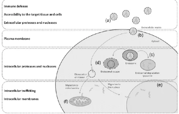
For transfection to occur, several conditions must be met: the DNA delivery system must pass undetected through the immune system (in vivo); it must reach the targeted cells; it must be able to interact with the cell’s membrane, in order to be internalized, either by endocytosis or through direct translocation; once the system is able to get inside the cell it should have the ability to avoid lysosomal degradation, by performing an endosomal escape; lastly the delivery system should release the encapsulated DNA near the target organelle (Figure 5)(27).
Figure 5 - Schematic of the path a gene delivery system must go through for transfection to successfully occur. From ref(27).
Direct translocation is an internalization process independent of both energy and proteins present in the cellular membrane, being mediated by the ability of the surfactant or surfactant/lipid mixture to interact and destabilize membranes with specific lipid composition(28). Endocytic pathways, however, are highly dependent on
the proteins present on the membrane, relying somewhat less on the chemical compatibility of the transfection system’s chemical nature with biological membranes. The downside is that the system must be able to escape the endosome in order to free the DNA. Such is the case in clathrin and caveolae-mediated endocytosis(27).
In the endocytic pathways it should be noted that the size of the transfection system is an important factor to consider, since the ideal size for internalization varies with the pathway (macropinocytosis being the pathway able to accommodate larger structures). If the complexes are too small, they might not be able to interact with enough membrane proteins to start the process; if too large, it might be impossible for the cell to proceed on their uptake.
1.1.4 Conventional vectors for transfection
The simplest approach to gene delivery is direct DNA injection, but this method has the drawback of being to process only one cell at a time, making it unusable for most medical applications(29). Many other strategies for gene
delivery
have been created inthe last years, from folded DNA boxes(30) to metallic nanoparticles(31), each with their own
advantages and disadvantages.
A common strategy when using nanoparticles is to adsorb the DNA at the particle’s surface(32) (Figure 6), thus allowing them to be more easily internalized by the
cell(33).
The vector that immediately stands out as an efficient way to transfect DNA into cells is the virus, since introducing genetic material into cells is the natural way for a virus to replicate – this causes naturally a high transfection efficiency. However, custom viruses have a high cost of production and require better safety standards due to their natural high mutability(34-35).
On the other hand, lipid-based transfection systems have great potential for DNA transfection due to their versatility.(29) There is a myriad of different lipids, surfactants and
combined lipid/surfactant system that can be used, allowing for greater refinement of transfection, depending on the types of cells and targets. Some lipids commonly used for transfection, due to their high efficiency and low cytotoxicity, are lipofectamine©(36),
monolein(37) and DOPE(38).
Lipid-based transfection systems work by encapsulating, adsorbing or otherwise securing DNA in self-assembled structures. These self-assemblies mimic the cell’s own
Figure 6 - Representation of DNA chains adsorbed to a nanoparticle's surface.
chemical and physical structure, allowing them to be internalized along with DNA. However, lipids suitable for this application are expensive, so their synthetic alternatives, the surfactants, are a desired field of study. Like lipids, surfactants also have both and hydrophilic and hydrophobic region, but their chemical nature is very distinct, usually having smaller size and molar mass. The downside of surfactants is their typically low biocompatibility, increasing their cytotoxicity. To get the “best of both worlds”, surfactant-based transfection systems usually have included in their composition some lipids to counter this effect, called the helper lipids(39). These mixed systems are usually referred
to as lipoplexes.
Helper lipids not only increase the biocompatibility of a surfactant-based system, but also can give those systems extra or augmented properties. An example of this is DOPE, which can be used to increase the efficiency of endosomal escape in transfection systems that use this route(28).
1.2 Lipids and Surfactants
Surfactants are a class of molecules with a unique chemical structure, that confers them unusual properties. These molecules have a hydrophobic part (apolar; usually a long hydrocarbon chain) and a hydrophilic (polar) part, both important in defining the physicochemical behaviour of the whole molecule. Surfactants can be classified by several properties, usually:
By the polar head group charge, as anionic, cationic, zwitterionic and non-ionic; By the polar head group chemical nature, as amines, carboxylates, amino acid
derived, etc;
By the number of both apolar chains (single-chained, double-chained, etc.) and polar head groups (monomeric, dimeric, etc.);
The combination of different polar head groups and hydrophobic chains in different levels of complexity allows an enormous variety of surfactants. (40-41)
One may think that these molecules may be somewhat rare to find outside an applied chemical environment, but that is far from the truth. In reality surfactants are present not only in research and industrial processes, but in living systems aswell. Lipids are the building blocks of all cell membranes and play other different roles in nearly all of the organisms, from intracellular signalling(42) to preventing lungs from collapsing on
themselves(43-44).
Figure 7 - Representation of a simple, one hydrophilic headgroup/one hydrophobic tail (left) and a more complex, one hydrophicilic headgroup/two hydrophobic tails (right) surfactants.
1.2.1 Surfactant properties
Since surfactants have a dual nature in terms of polarity (they are both hydrophilic and hydrophobic) in separate zones of the molecule, some peculiar properties appear.
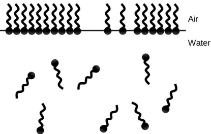
While in solution, surfactants tend to concentrate more at the surface or interfaces of the solution than in the bulk due to the presence of the hydrophobic tail, as its contact with water molecules is not as favourable as the contact with air. Furthermore, the creation of an interface between two media of different polarities, such as water/air is also unfavourable, giving rise to an interfacial tension (i.e. excess Gibbs energy per unit area of surface) and an increase of the overall Gibbs energy of the system(27). This makes
it thermodynamically favourable for the surfactant molecules to move to the interface in order to make the contact between the two more favourable and reducing the Gibbs energy.
In the case of a water/air interface, the surfactant molecules gather on the surface and reduce the Gibbs free energy of the area of contact between the two media (Figure 8). This reduces the energy per area unit that is necessary to keep the two phases separate, as the surfactant acts a stable link between them. Furthermore, the surfactant molecules intercalate with the water molecules at the surface (which are more structurally organized than in the bulk), making them lose cohesiveness among them(45),
thus lowering the surface tension.
Air
Water
Figure 8 - Visual representation of the air/water interface and surfactant adsorption on it.
1.2.1.1 Surface tension
Surface tension manifests itself as the differences between the Gibbs energies of molecules located at the surface and the bulk of a liquid. Due to this difference, the surface of the liquid has a tendency to reduce its area of contact with air.
In the case of a liquid-air interface (a surface), different forces act on the surface’s molecules and bulk molecules (Figure 9). In the bulk, solvent molecules are completely surrounded by equal molecules and have forces pulling them in all directions simultaneously, with a resulting null net force. At the surface, however, molecules are not surrounded by the same number of molecules and the resulting net force pulls them inward into the solution (Figure 9). Additionally, the surface acquires an elastic-like behaviour due to this aspect.
Figure 9 - Representation of forces acting on water molecules at the surface and in the bulk. From ref(46).
This greater cohesiveness, between liquid-liquid molecules than liquid-air molecules, makes creation additional surface area energetically unfavourable. Due to these molecular aspects, the surface tends to reduce its area in order to reduce the unfavourable interactions.
Surface tension can then be thermodynamically defined by the reversible work need to expand this surface area, as demonstrated in eq. [ 1 ], where
γ
is the surface tension,w
the reversible work and ΔA
the increase in total surface area.A
w
[ 1 ]
For a planar surface and constant pressure and temperature, surface tension can be defined in terms of Gibbs energy (eq. [ 2 ]).
T p
A
G
,
[ 2 ]1.2.2. Self-Assembly
As more and more surfactant is added into a solution, the surfactant adsorption at the surface starts to become thermodynamically unfavourable (this means the surface tension can’t be infinitely lowered). Since surfactant molecules cannot adsorb to the interface anymore the surfactant molecules start organizing themselves, in a process called self-assembly, in organized structures (Figure 10), in order to minimize the contact between the tails and the solvent, thus minimizing the hydrophobic effect.
The concentration at which the surfactant molecules start self-assembling is called the critical aggregation concentration (cac). Once the critical micelle or aggregation concentration has been achieved in a solution, it will not change with the addition of more surfactant molecules. The extra molecules will form self-assembled structures, maintaining the solution’s unimer concentration constant.
However, surfactants do not all organize in the same manner, with different molecules assembling in different types of structures, such as micelles and vesicles, among others. It should be noted that in many cases it is not only the nature of the molecule that defines the structure but also the concentration of said molecules.
The type of structure a surfactant self-assembles into can be predicted to some extent by two distinct models, discussed below.
Water Air
Figure 10 - Representation of a surfactant solution at the cmc and formation of micelles.
1.2.2.1 Surfactant packing parameter
The surfactant packing parameter associates the volumetric geometry of a molecule to the structures it is likely to self-assemble into, in a solution. This parameter is defined by the ratio between the actual volume occupied by the molecule, defined by the volume of the hydrocarbon chain (Vhc; Figure 11), and the theoretical volume it would
occupy considering a cylindrical shape with the optimal area (ahg) of the polar headgroup
and the length of the hydrocarbon chain (lhc), as seen in eq.[ 3 ].
hc hg hc S
l
a
V
P
[ 3 ]Figure 11 - Visual representation of the volumes used for the calculation of the packing parameter Ps. From
ref(47).
It is considered that when Ps<1/3 (cone shaped molecule), surfactants will
preferably assemble into spherical micelles, with cylindrical micelles arising at 1/3<Ps<1/2 (truncated cone shape). At 1/2<Ps<1 the preferred structures are vesicles
and flexible bilayers (as Ps approaches 1), with planar extended bilayers at Ps=1. Above Ps=1 surfactants will tend to form reverse spherical or reverse cylindrical micelles (Figure
Figure 12 - Visual representation of the relation between the surfactant packing parameter and the structure formed. Adapted from ref(27).
It is difficult to calculate the value of ahg due to many variables that interfere with
it (such as the presence of salts in the solution), but the values of Vhc and lhc can be
estimated for simple surfactants by the formulae (eq. 2 and eq. 3) below, where nc is the
number of carbons in the hydrocarbon chain:
c hc
nm
n
V
/
3
0
.
0274
0
.
0269
[ 4 ] c hcnm
n
l
/
0
.
154
0
.
127
[ 5 ]1.2.2.2 Spontaneous curvature
As an alternative to the surfactant packing parameter model, the spontaneous curvature model is especially useful for the description of different kinds of bilayer based structures, such as vesicles and planar bilayers.
In this model, all structures are considered to be formed by surfactant films, with the structure formed defined by the curvature of the film. This can be described by the following equation (eq. 4), in which H0 is the spontaneous curvature, and R1 and R2 are
the radii of curvature in perpendicular directions.
2 1 01
1
2
1
R
R
H
[ 6 ]
Each radius, R, has an associated signal (positive or negative) related to the direction of a vector that defines it on the self-assembled structure. By convention the polar region is always taken as positive (Figure 13).
Figure 13 - Visual representation of the curvature in self-assembled structures and respective radii. From ref(47).
A regular spherical micelle has two defined radii with a positive signal, giving it a spontaneous curvature of 1/R, while a planar bilayer film has a H0 of ≈ 0 (zero curvature)
since both its radii are immeasurable (considered infinite). A reverse spherical micelle has H0 = -1/R, since its polar region is in the innermost part of the sphere.
The spontaneous curvature adopted by a surfactant film is always the one that minimizes the Gibbs energy of the system. Unlike the packing parameter, which relates the shape of the final aggregate to the nature of the individual molecule, the spontaneous curvature refers more to the physical properties of the film as a whole.
1.2.3 Structures
While alone in a solution, each individual surfactant molecule is called an unimer, the basic unit of any assemblage. By order of complexity, the first and simplest self-assembled structure that can be formed is the micelle. Micelles can have several shapes, depending on the surfactant concentration and packing parameter, among them spherical, elongated, cylindrical and worm-like shapes. In all these structures, the hydrocarbon chains are directed to the centre, reducing their contact with the aqueous media.
In certain conditions, such as packing parameter > 1 or the presence of a high amount of a hydrophobic substance (such as an oil), reverse micelles can be formed, which have their hydrophobic tail turned outward.
Next on the order of complexity are the vesicles (Figure 14). These usually spherical structures are formed by a curved bilayer of the surfactant, having an aqueous pool. This structure is much larger than regular micelles and have typically slower dynamics, but unimers in it still exchange with those in solution over time in dynamic equilibrium. The large aqueous pool is a particularity of this structure that makes it
especially useful for drug delivery, since it can contain and protect water-soluble molecules.
Figure 14 - Cross-section representation of a liposome. From ref(48).
Bilayers are composed of opposing layers of surfactants, with either the hydrocarbon tails or the headgroups in contact, depending on the polarity of the solvent. They can be categorized in 3 distinct morphologies, closed (vesicles), planar and bicontinuous.(49)
1.2.4 Gemini surfactants – Structure and properties
Gemini surfactants are composed of two hydrophilic and two hydrophobic moieties, covalently linked to each other usually at the headgroup level via a unit that is called the spacer(2).
Like conventional surfactants, gemini can have innumerable structural variations. They can be classified mainly by symmetry (symmetric if both monomers have identical headgroup and hydrocarbon tail, asymmetric if they do not), charge of the headgroups (neutral, cationic, anionic or catanionic), chemical nature of both the headgroups and spacer(50-51), length of the hydrocarbon chains, origin of the headgroups (amino-acid
derived, sugar derived(52), among others).
Gemini surfactants, despite their high synthesis costs, have several advantageous properties over conventional single-chained surfactants, such as a lower cmc, higher surface activity and higher structural versatility(27, 53).
The higher surface activity and low cmc are especially sought after in several areas, industry among them, since it lowers the amount of compound needed in comparison to a conventional surfactant to achieve the same effect. This helps turn industrial processes more efficient(54) and less prone to contaminations, helping to
prevent toxicity in medical and cosmetic applications(55). Some gemini are even reported
to have an antimicrobial effect(54, 56-58).
Figure 15 - Bis-quat gemini surfactant
alkanediyl-α,ω-bis(dodecydimethylammonium bromide). Spacer with variable length. Adapted from ref(2).
In recent years gemini of various chemical nature and structural configurations have been studied for their applications in gene and drug delivery due to their efficiency and low cytotoxicity(54, 59-60), especially those derived from amino-acids(23, 59). In this work
we approach serine-derived gemini surfactants.
1.2.4.1 Serine-based gemini surfactants
In recent studies, gemini derived from several amino acids have shown to be even better than conventional surfactants, for medical applications due to their even lower cytotoxicity(61-63).
These amino acid derivatives show higher biocompatibility, due their structural likeness to biological molecules. This allows them to readily interact with biological membranes, facilitating the delivery of drugs/DNA into the cell, either by fusion with the membranes or by a facilitated internalization.(60)
Serine-based gemini were synthesized for the first time in 2012(61), comprising of
two N-alkylated serine residues linked by a simple hydrocarbon chain spacer.
Figure 16 - Example of a gemini surfactant molecule. Serine derived gemini with a spacer of twelve carbons and both hydrocarbon chains with twelve carbons.
1.2.5 Compaction and transfection of DNA by surfactants
The interaction of DNA with the surfactant of a gene delivery system is of paramount importance to determine its ability to form stable and usable forms of aggregates for use in transfection.
The DNA molecule possesses multiple negative charges along its double helix due to the phosphate groups present in its structure. These negative charges allow cationic surfactants, and their self-assembled structures to interact with the DNA chain. Most surfactants used for this purpose are cationic, given that the opposite charge grants a much stronger electrostatic interaction. However, uncharged surfactants can also be employed, although the nature of interaction is different, since they interact by van der Waals and hydrophobic forces alone, which are generally weaker(64-65).
The type of self-assembled structure present in solution before DNA complexation will greatly change the final conformation of supramolecular surfactant:DNA aggregates(66). For example, it was reported(67) that when DNA is added
to existing micellar systems it tends to form compacted globular complexes, with chains of DNA connecting several of these globules (Figure 17). Furthermore, with vesicle-forming gemini surfactants, it was seen that the addition of DNA caused a rearrangement of the system, forming inverted hexagonal structure, containing DNA(27, 67). This
aggregation of DNA with self-assembled structures is often called DNA packing. For cationic surfactants, the structures of the surfactant:DNA complexes depends greatly on the charge ratio between the two, leading to different levels of packing.
Mixtures of cationic and neutral surfactants are often used to balance the magnitude of the interaction with DNA, preventing either excessive DNA packing (which would difficult its later release inside the cell) or too loose or non-existent packing.
Figure 17 - Example of DNA packing in an environment with cationic spherical micelles, as reported using electron microscopy. From ref(68).
Concerning gemini surfactants, the compaction of DNA might involve a chain effect, derived from the combined effect of hydrophobic and electrostatic interactions, promoting the interaction of additional surfactant molecules over time, as more molecules are present, starting from a small cluster(27). This process has an enthalpy
gain, thus, being favoured by a low cmc(27, 69).
It was found that the most efficient compaction was mediated by those with short spacers (n=2, n=3)(27, 70), which form disperse micelle-like aggregates of the two
components.
For transfection purposes it was found that generally, the transfection ability is higher, for lower spacer lengths, correlating to the area occupied by the surfactant head-group(27). This might be explained by the fact that short spacer maintain the positive
charge of the cationic head-groups, in a distance more favourable for interaction with the 4.9
Å
spaced, negatively charged phosphate groups in DNA(27). Additionally, it is notpossible to generalize further the influences of the chemical nature of the bond between headgroup and spacer(27).
1.3 Aim of this project
Mitochondrial gene therapy techniques and protocols are becoming ever more popular due to their potential ability to treat otherwise incurable diseases and syndromes, such as the ones referred in chapter 1.1.1. Like all gene therapies, the treatment efficiency depends on the delivery system chosen. This system must able to both survive the biological environment (degradation, inactivation, etc.) and be able to safely deliver the genetic cargo to the inside of cells. Many strategies and types of delivery systems can be adopted for this purpose. In this project, the strategy followed is the use of surfactant and lipid-based colloidal DNA carriers, with the specific objective of targeting the mitochondria, inside cells.
This project is part of a more global study of gemini surfactants, both conventional and amino-acid derived, and their transfection abilities, developed in the research groups of University of Porto and University of Coimbra(23, 59-61, 71-75). The studies that have
already been published, present not only the advantages of gemini surfactants to their monomeric counterparts in terms of DNA compaction, transfection efficiency and cytotoxicity, but also the advantages of amino-acid derived regular and gemini surfactants in terms of biocompatibility. In this project, we assess the influence of varying length of the hydrocarbon chains (from twelve to eighteen carbons long) in serine derived cationic gemini surfactants, all with the same hydrocarbon spacer (twelve carbons long). The development of this project can be divided in three major parts: (1) organic synthesis of the serine-derived gemini surfactants; (2) Physicochemical, interfacial and morphological characterization of the neat surfactants and their complexes with DNA and helper lipids; (3) biological studies of the transfection efficiency and cytotoxicity of the complexes, in vitro; (4) comparisons with previous studies.
Chapter 2: Materials and
methods
2.1 Serine based gemini surfactants organic
synthesis
2.1.1 Reagents and preparative reactions
With the synthetic pathway used, both the spacer and side chain carbons must be added to the serine derivative in their aldehyde and dialdehyde (for the spacer) forms. Due to the overall instability of these long chain aldehydes, they must be synthesized right before their use in the main synthesis.
All the aldehydes variants were synthesized using the same reaction, the tetrapropylammonium perruthenate (TPAP) catalysed oxidation of their respective alcohol forms(76), which are available commercially. TPAP was used in a molar quantity
equal to 5% of the reagent.
Figure 18 - Representation of the reaction of oxidation of 1,12-dodecanediol to 1,12-dodecanedial.
Figure 19 - Representation of the reactions of oxidation to aldehydes of the several long chained alcohols used.
2.1.2 Synthetic pathway
The synthesis pathway for the (nSer)2N12 gemini surfactants used in this work
has two initial reductive amination reactions. Both aminations were processed under Argon inert atmosphere with sodium triacetoxyborohydride (NaBH(OAc)3) as the
reducing agent.
The first reaction is used to attach the variable length hydrocarbon chain onto a o-methylated (in the carboxyl group), o-terc-butyl protected (in the alcohol group) serine, creating (nSer) monomers. In the second reductive amination the monomers are chained together to each other and the twelve carbon long spacer, by carefully maintaining reaction stoichiometry to avoid excess formation of unwanted species. The resulting
product was then doubly methylated with methyl iodide (CH3I) on both ternary amine
groups, turning them into quaternary ammonium groups, with iodide counter ions. Lastly, the terc-butyl group was removed with trifluoroacetic acid (TFA), exchanging the iodide counter ions for trifluoroacetate counter ions in the process.
2.1.3 Purifications
2.1.3.1 Column chromatography
To ensure that a minimum of side products are present at the end of each reaction step, column chromatography was employed to purify the resultant mixture of each step and isolate the desired product.
These purification steps in the middle of the synthesis chain prevent the formation of compounds that could be inextricable from the desired product at the final step, when the final product is fully formed.
The columns used have an embedded ceramic filter at the bottom and were packed with a thin layer of sodium sulphate (Sigma Aldrich) followed by fine silica, the stationary phase in the system. The mobile phase, or eluent mixture, depends on the reaction step that was purified, due to the different polarity needs of each intermediate product.
Figure 21 - Flash column chromatography schematic. From ref(1).
The method employed differs slightly from the regularly used process since it was done under artificial air pressure, with a small air pump at the top of the column, a flash column chromatography (Figure 21).
After the column separation, the relevant fractions (assayed by Thin Layer Chromatography (TLC)) were combined and the solvent was removed using a rotary evaporator, readying the product for the following step.
2.1.3.2 Nuclear magnetic resonance (NMR)
Nuclear magnetic resonance is a technique that employs the ability of atomic nuclei to absorb and re-emit electromagnetic radiation when a magnetic field is present. Some atomic nuclei, such as 1H, 13C, 14N, 15N, 19F, among others, are magnetic
because of their charge and because they behave as if spinning. This magnetic property allows them to interact with magnetic fields, in a manner similar to bar magnets. However, unlike bar magnets, the atomic nuclei do not always align themselves to the magnetic field, due to quantum restrictions; they can also oppose it. These two configurations of the atomic nuclei are of different energy, lower energy being the aligned configuration while the opposed configuration has a higher energy level (Figure 22).
Figure 22 - Representation of the different configuration of atomic nuclei without and with the presence of a magnetic field Bo and the energy gap between the aligned and opposed configurations. Adapted from ref(77).
The energy difference between the two configurations is unique to the type of nucleus in a given magnetic field and can be translated to an electromagnetic frequency by the Bohr relationship (eq. [ 7 ])
hv E
[ 7 ]
As an example, the 1H nucleus has an energy difference (ΔE) of approximately
6.6 x 10⁻²⁶ J in a magnetic field of intensity 2.35 tesla (T); thus, the correspondent
frequency is 100 MHz, on the radiofrequency band of the electromagnetic spectrum. If the field intensity changes, so does the energy difference, increasing proportionally to the magnetic field intensity – with a field strength of 7.0 T for example, the frequency of the energy difference would be 300 MHz (Figure 23).
While in the magnetic field, if the nuclei are irradiated with the radiofrequency that matches the frequency of the energy difference they will undergo transitions from the aligned state to opposed and vice-versa, absorbing part of the radiofrequency transmission energy. This process is called resonance.
The resonating frequency of these nuclei vary not only with the strength of the applied magnetic field (Figure 23), but also with the chemical environment they are in, such as the neighbouring nuclei in a molecule with different electron densities, which change their magnetic susceptibilities. The change in resonating frequency by the chemical environment is called a chemical shift and is usually expressed in ppm (parts per million), and represented by the greek letter δ.
Figure 23 - Changes in the resonant frequency of 1H nuclei with the change of the magnetic field's strength.
Adapted from ref(77).
By measuring both the frequency at which the nucleus absorbs the radiofrequency signal and how much it absorbs, it is possible to build a spectrum that can be read to identify the nature of the nuclei (and their chemical neighbourhood via the
chemical shift) and the number of these nuclei in the molecule. It is possible then to reconstruct the structure of the entire molecules by these data alone. However, it may require more than one NMR analysis to do so in more complex molecules.(77)
NMR spectra peaks can also be split in several components due to spin-spin coupling, which arises from the nuclei interference with each other because of their innate small magnetic field.
In this work, 1H NMR was used to determine the structure and purity of the
products in the intermediate steps of the synthesis, while the final product of each synthesis was analysed by four distinct techniques: 1H, 13C, COSY and HSQC, to ensure
that the products are in good purity for the rest of the work. With the exception of the final NMR spectra, for which the product was dissolved in deuterated acetone or dimethyl sulfoxide, for the intermediary NMR spectra, the products were dissolved in deuterated methanol.
2.1.3.1 NMR peak attributions
The synthesis of the various gemini surfactants were carried out by the procedure previously described.
The characterization of the intermediate and final products of the synthesis was carried out by 1H and 13C (final products only) NMR, presented in the supplementary
information section.
The NMR data for (12Ser)2N12 is not shown, since it coincides with data already
2.2 Surfactant characterization
2.2.1 Tensiometry - Wilhelmy Plate Method
There are several methods that can be employed to determine the surface tension of a liquid, using different physical properties and characteristics. These methods can be divided in three distinct categories:
Based on force: such as Wilhelmy Plate method, Du Noüy Ring method and capillary elevation method;
Based on pressure: such as maximum drop pressure method;
Based on shape: such as sessile drop method and pendant drop method.
The shape-based methods need low amounts of liquid to determine the surface tension and are able to achieve good precision, but are technically difficult to execute. They may require some correction of the experimental values obtained (the sessile drop method requires chromatic aberration corrections when a camera is used to determine the contact angle).
Force-based methods are also in general very precise, but much simpler to execute, the downside being that they require expensive equipment (with the exception
Figure 24 – DCAT11 tensiometer used for the surface tension measurements.
of the capillary elevation method). The Wilhelmy Plate method was used for all surface tension measurements in this work.
In this method, the Wilhelmy plate is attached to a balance, and a vessel with the liquid to be measured is placed under it. The balance is zeroed and the vessel with the liquid is then elevated until the plate breaks the liquid’s surface. At this point, a meniscus forms around the length of the plate due to the surface tension, which exerts a downward force, pulling the plate (Figure 25). This force is measured by the balance and is used to calculate the surface tension by the following formula (eq. [ 8 ]).
cos
plate measuredL
G
m
[ 8 ]Here, γ is the surface tension, mmeasured is the value
measured by the balance, G is gravitational constant, Lplate is
the plate’s perimeter and θ is the contact angle of the liquid with the plate. Since the plate is made of a rough platinum or platinum-iridium alloy, the contact angle θ=0°, thus being
completely wetted by the liquid. The equation can then be simplified (eq. [ 9 ]).
L
F
[ 9 ]Experimental procedure
For this work, a DCAT11 tensiometer from Dataphysics was used. This apparatus consists of a sealed chamber (to stop air drafts from affecting the measurement) with a motorized elevation platform of high precision (with an error of ±0.0001 mm) with a thermostatization module (fed from an external source, a thermostated bath from Julabo), and a high precision balance (±0.00001 g) on the top.
A glass vessel was used for the solution, previously washed with deionized water and ethanol, and dried in an oven at 100°C. The Wilhelmy plate was also washed with deionized water and ethanol, but dried in a butane flame.
For all experiments the vessel was loaded with 25.0g of ultra-pure water (Millipore™) and the surface tension measured, to further assess the purity of the water. Surfactant solutions were prepared within 24 hours of the measurement with ultra-pure water and maintained overnight in an oven at 25°C.
Aliquots of the surfactant solution under study were transferred to the vessel, using micropipettes (Gilson™). For each aliquot added the solution was magnetically agitated for 3 minutes, followed by 1 minute of rest. The plate was then immersed in the solution and left to stabilize for at least 5 minutes.
Each curve obtained by this method contains 20 to 29 surface tension data points, each for an added aliquot.
Figure 26 - Inner chamber of the DCAT11 tensiometer, with attached Wilhelmy plate, during a measurement.
From the surface tension curves, one can gather relevant parameters, such as the surface tension of the dispersion at the cmc, the maximum surface excess concentration, Γmax (page 34) and the minimum surface area per molecule, aSmin (page
2.2.2.1 Calculating the cmc
The surface tension obtained was plotted versus the natural logarithm of surfactant molal concentration.
The critical micelle concentration (cmc) was determined by intersecting two linear regressions of two sets of data points, the first one being the set that contains the data points that form a regression with the highest slope and the second the set contains the data points at which the surface tension is stabilized (referred as the surface tension plateau), as graphically exemplified below (Figure 27). The concentration at this point of intersection yields the cmc.
Figure 27 - Graphical example of the method used to calculate the cmc.