Gomes, C.1; Lino, J. 2, Cardon, L.3, Pouzada A. S. 1, Pontes, A. J. 1
1 Institute for Polymers and Composites, University of Minho, Guimarães, Portugal 2Dept. Mechanical Engineering, University of Porto, Porto, Portugal
3University College Gent, Gent, Belgium
Abstract
Precision products are coming into the market after increasingly shorter periods of development and production. This implies reduced design periods for the products and the tools. The mouldmaking industry is facing this reality by integrating the stages of conception, development and tool manufacturing in the design process. This integration use alternative fabrication technologies employed in rapid prototyping and tooling. Shorter lots of plastic components are consequently becoming possible through the use of hybrid moulds that use alternative non-metallic/metallic materials in the moulding blocks. The consideration of the wear and thermal characteristics of the moulding blocks are important for guaranteeing the precision performance of the hybrid moulds.
The implementation of CAE tools during the development of an injection mould for a new product has already shown advantages. They can be used to foresee the mould behaviour during the injection moulding process without even start building the tool and minimise the risk of mistake during the design process.
Aspects associated to the design and performance of an injection hybrid mould for a deep part are considered in this paper. Conventional Machining, Resin Casting and Prometal technologies were used to produce the moulding cores. In particular, the mechanical and the thermal behaviour of these hybrid components were assessed and compared with CAE simulations. The injection moulding programme was carried out with unreinforced polypropylene.
Introduction
The mould making industry has been pressed with the need of rapidly introducing new products in the market, with shorter life cycle, which leads to smaller development periods and production runs [1, 2].
These competitive factors, life cycle reduction and high variety of products, led to the development of rapid prototyping and rapid tooling technologies (RPT) with an increasing importance in this industry [3].
The objective of rapid and economically producing injection moulds for shorter runs suggested the integration of RPT with conventional manufacturing technologies. The concept of Hybrid Injection Moulds embodies the idea of assembling conventional metallic mould structures with moulding blocks obtained by RPT [4]. As hybrid moulds also aim at economic advantages their overall design process must be carefully considered in order to obtain the best price/performance ratio for the reduction of the time-to-market [5, 6].
In the design process, the assessment of the thermo-mechanical behaviour is essential for the improvement of the tool performance, as well as, costs, tool life time and accuracy aspects. Therefore, it is important to predict the influence in the injection process and final part properties of using non-metallic materials in the moulding blocks [4, 7].
Experimental programme
The main objective of this study was the evaluation of the thermo-mechanical performance of moulding blocks manufactured by conventional and rapid tooling techniques.
It was also envisaged the study of the influence on the part shrinkage of the moulding block material. The metrology assessment was made with a 3D measuring machine, 2 hours after injection moulding the parts.
The work was developed in two phases: a CAE analysis, using the package Moldex 3D (CoreTech System Co., Ltd, Hsinchu, Taiwan), to predict the injection moulding process when different core materials were used, and experimental moulding tests using a unreinforced polypropylene from DOMO – Domolen 1100 N.
The main properties of the moulding material are presented in Table 1.
Table 1 – Properties of the injection moulding material
DOMOLEN 1100 N
Density (Mg/m3) 0,91
MFR (g/10 min) [230ºC/2.16kg] 12 Tensile Modulus of Elasticity (MPa) 1550
Tensile Yield Stress (MPa) 35
The processing conditions used in the experimental study are shown in Table 2.
Table 2 – Injection moulding conditions
Processing Program Conditions
Melt temperature (ºC) 230
Mould temperature (ºC)* 30 50
Holding pressure (MPa)** 22 29
Holding time (s) 10
Cooling time (s) 20
* Temperature of the water circuit
** Corresponding to 30 and 40 bar of hydraulic pressure of the injection machine
The moulding used in the experiments is a simple tube with a considerable height (60 mm), as presented in Figure 1.
Fig. 1. Moulding of the case study
Injection mould
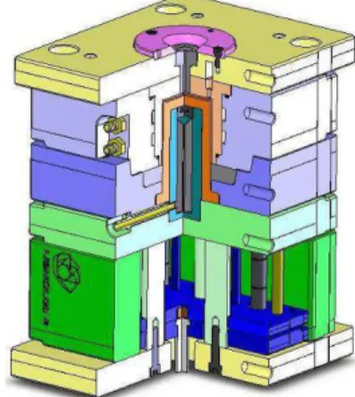
The hybrid mould for this study was designed to receive different interchangeable core and cavity blocks, made by conventional machining and RPT. Specific aspects of the mould design were considered to facilitate and guarantee the interchangeability of the various moulding blocks. A schematic view of the tool is shown in Figure 2.
Fig. 2. Hybrid Mould of the case study
The adopted solutions related with the moulding blocks and the cooling system are:
− Core and cavity blocks supported by the respective retainer plates, to avoid the direct screwing of the moulding blocks. This is required because of the limited strength of the resins to be used;
− In the cavity side, the water circuit was machined directly in the cavity retainer plate to avoid the machining of the cavity block, as well as the O-rings housing;
− In the core side, the cooling system consists of an independent baffle-type system that is assembled on the mould structure. This solution avoids the costly and delicate machining of the cooling channels inside the resin core.
Manufacturing of moulding blocks
The core and cavity elements were manufactured in different materials and using various technologies, with the objective of studying their thermal and mechanical behaviour.Conventional Machining
The core and cavity blocks were manufactured in tool steel (1.2312), known for its excellent machinability and uniform hardness. The shape of these blocks enabled the machining by turning.
Epoxy tooling
The commercial resin Neukadur VG SP 5 from ALTROPOL, a high performance and heat resistant material specially developed for injection mould prototypes, was used to produce the core block. This epoxy resin is filled with mineral and metallic fillers that confer an improvement of the mechanical and thermal properties of the casting compound [8].
3D – Printing: Prometal
A Prometal core was developed using a S4 420 material, a stainless steel bronze infiltrated, with properties similar to P-20 steels, and improved thermal transfer.
The main properties of the used moulding blocks materials are presented in Table 3.
Table 2 – Properties of the moulding blocks materials
Materials Properties Steel (1.2312) Prometal (S4 420: 60% Stainless Steel + 40% Bronze) Neukadur (Resin Casting) Density (Mg/m3) 7,85 8,07 2,7 Hardness 55 HRC 26 HRC 90 Shore-D Tensile Strength (MPa) ≈ 1000 682 50 Modulus of Elasticity (GPa) 200 147 9,8 Coefficient of Thermal Expansion (x10-6 ºC) 12,9 7,2 30-35 Thermal conductivity (W/m.K) 36,5 85 0,7
Mould Instrumentation
To monitor the behaviour of the various moulding blocks the used mould was instrumented for pressure and temperature determination in the core and cavity. The cavity was instrumented with a thermocouple and a pressure sensor near the gate zone (Figure 3).
Fig. 3. Temperature and pressure sensors location in
the cavity block
The core was monitored with temperature sensors across the core thickness (Figure 4), for a better understanding of its thermal behaviour. This is critical due to the moulding shrinkage over the deep core.
Fig. 4. Temperature sensor location in the core block
Thermo-mechanical environment and
shrinkage
The effect of the shrinkage in the dimensional precision is of great importance in the quality of the injection moulded part. Therefore, the study of this effect is very important when producing injection moulded parts, using alternative mould materials with thermal properties different from conventional steel moulds. Thus, the work herein intends to establish the effects of the thermal conditions on part shrinkage, associated to the different materials used in the injection mould.
The process conditions that affect most the shrinkage are the holding pressure, the melt and mould temperatures. The parameter that presents higher influence on the part shrinkage is the holding pressure, which lowers the shrinkage when it increases. It was also shown that the holding pressure has different effects along the flow length, which is more evident in locations away from the gate [9].
Results and Discussion
CAE Simulations
Moldex 3D was the CAE simulation package for injection moulding process prediction of the plastic part, using the various moulding cores. Using the Moldex 3D program, the model mesh is imported from the Rhinoceros CAD tool to start the simulation (figure 5). All the conditions necessary
T1 T2 Temperature Sensor Pressure Sensor
to run the injection moulding process simulation are specified, namely: part and mould materials, injection moulding machine, processing parameters and envisaged type of analysis.
Fig. 5. – Mesh Model exported to Moldex 3D
Figures 6 and 7 shows the results obtained for the pressure and temperature profiles using one of the sets of the moulding blocks (steel-resin).
Fig. 6. – Pressure Profile in the Filling Phase
Fig. 7. – Temperature Profile at the Cooling Phase
The thermal results from the simulation are shown in figure 8 for the three different sets of moulding blocks (cavity-core): steel-steel, steel-Prometal and steel-resin.
According to the simulation results, the three temperature profiles are distinct. This is more evident in the case of the resin core, which is expectable, due to its extremely lower thermal conductivity, when compared with steel and Prometal (see Table 3).
0 20 40 60 80 100 120 140 160 180 200 0 5 10 15 20 25 time (s) T e m p e ra tu re ( ºC ) T core simulated - Resin Core T core simulated - Steel Core T core simulated - Prometal Core T cavity simulated - Steel-Steel inserts
Fig. 8. Temperature predictions with Moldex 3D
Injection Moulding Tests
In order to assess the thermo-mechanical behaviour of the hybrid mould, three different sets of moulding runs were performed, varying the core material: steel, Prometal and epoxy resin. The mouldings were made in polypropylene. To analyse the effect of the mould material on the part shrinkage, two parameters were set as variables for this study: holding pressure (22 MPa and 29 MPa) and mould temperature (30ºC and 50ºC in the water circuit). The pressure and temperature data were recorded for this processing conditions and the results obtained presented in figures 9 to 11.
0 1 2 3 4 5 6 7 8 9 10 0 5 10 15 20 25 30 35 time (s) C a v it y P re s s u re ( M P a ) Resin Steel Prometal
Fig. 9. Cavity pressure data for a holding pressure of
22 MPa and a mould temperature of 50ºC
0 1 2 3 4 5 6 7 8 9 10 0 5 10 15 20 25 30 35 time (s) C a v it y P re s s u re ( M P a ) Resin Steel Prometal
Fig. 10. Cavity pressure data for a holding pressure of
29 MPa and a mould temperature of 50ºC
0 1 2 3 4 5 6 7 8 9 10 0 5 10 15 20 25 30 35 time (s) C a v it y P re s s u re ( M P a ) Resin Steel Prometal
Fig. 11. Cavity pressure data for a holding pressure of
29 MPa and a mould temperature of 30ºC
As expected, the increase of the holding pressure raises the cavity pressure, as it shown in figures 9 and 10. However, the cavity pressure profile diverges in the various core materials, this being more evident for the epoxy resin, where higher values of pressure were obtained. This result can be explained by the lower thermal conductivity of the resin, which causes a delay on the solidification of the plastic part.
The influence of the mould temperature in the cavity pressure can be observed in the figures 10 and 11. For the three core materials, there was no large difference in the cavity pressure upon increasing the mould temperature.
Figures 12 and 13 shows the different temperature profiles among the core thickness, at the locations T1 and T2, demonstrating the diverse thermal behaviour, mainly in the resin core, indicating a clear delay in the temperature recovering, due to its obviously lower thermal conductivity, when compared with the steel and Prometal materials.
0 10 20 30 40 50 60 70 80 90 100 0 5 10 15 20 25 30 35 time (s) T e m p e ra tu re ( ºC ) T1 - Steel core T1 - Prometal core T1 - Resin core Tcavity: Steel-Resin Tcavity: Steel-Prometal Tcavity: Steel-Steel
Fig. 12. Temperature data for the various materials at
location T1, using the cavity temperature as reference (holding pressure=29 MPa; mould temperature=30ºC).
0 10 20 30 40 50 60 70 80 90 100 0 5 10 15 20 25 30 35 time (s) T e m p e ra tu re ( ºC ) T2 - Steel core T2 - Prometal core T2 - Resin core Tcavity: Steel-Resin Tcavity: Steel-Prometal Tcavity: Steel-Steel
Fig. 13. Temperature data for the various materials at
location T2, using the cavity temperature as reference (holding pressure=29 MPa; mould temperature=30ºC).
Figure 14 represents the comparison between the simulation results (represented by lines) and experimental results (represented by lines with points) , in the three sets of moulding blocks: steel-steel, steel-Prometal and steel-resin.
0 20 40 60 80 100 120 140 160 180 200 0 5 10 15 20 25 time (s) T e m p e ra tu re ( ºC ) T cavity experimental - Steel-Steel inserts T cavity simulation - Steel-Steel inserts T - Steel Core T - Prometal Core T - Resin Core
Fig. 14. Temperature data: comparison between
In the assessment of the influence of the holding pressure and the mould temperature in the part shrinkage (figures 15 to 17) it was observed that the variation of the holding pressure and the mould temperature did not cause considerable differences. 0,00 0,20 0,40 0,60 0,80 1,00 1,20 1,40 1,60 1,80 2,00 0 10 20 30 40 50 60 Flow Lenght (mm) S h ri n k a g e ( % ) Prometal Core Resin Core Steel Core
Fig. 15. Variation of shrinkage along the flow length
(holding pressure=22 MPa; mould temperature=50ºC)
0,00 0,20 0,40 0,60 0,80 1,00 1,20 1,40 1,60 1,80 2,00 0 10 20 30 40 50 60 Flow Lenght (mm) S h ri n k a g e ( % ) Prometal Core Resin Core Steel Core
Fig. 16. Variation of shrinkage along the flow length
(holding pressure=29 MPa; mould temperature=50ºC)
0,00 0,20 0,40 0,60 0,80 1,00 1,20 1,40 1,60 1,80 2,00 0 10 20 30 40 50 60 Flow Lenght (mm) S h ri n k a g e ( % ) Steel Core Resin Core Prometal Core
Fig. 17. Variation of shrinkage along the flow length
(holding pressure=29 MPa; mould temperature=30ºC)
However, observing in detail the figures 15 and 16, it is seen that the increase of the holding pressure caused higher variation in the shrinkage of the resin core moulded parts.
Conclusions
From the results of the injection moulding tests the holding pressure is the processing condition that
causes higher variations in the cavity pressure behaviour and in the part shrinkage.
The differences obtained were more evident in the epoxy core, due to its lower thermal conductivity. The simulation with Moldex 3D adequately predicted the behaviour of a steel mould, but produced large differences for RP materials. This is may be due to the inaccurate thermal characterisation of the epoxide composite and the sintered Prometal.
Acknowledgments
The authors acknowledge the financial support of the European Project EUROTOOLING 21.
Keywords
Injection Mould Design, Rapid Tooling, Hybrid Mould, CAE.
References
[1] Pontes, A.J.; Queirós, M.P.; Bártolo; P.J., Pouzada, A.S. - A study on design and performance of hybrid
moulds for injection moulding; 5th Int. Conf. Industrial
Tools, Velenje: April 2005.
[2] Queirós, M.P.; Pontes, A.J.; Pouzada, A.S. -
Performance assessment of hybrid moulds for injection moulding; Int. Conf. Polymers and Moulds
Innovations (PMI), Gent: April 2005. [3] Henriques, E.; Peças, P. - Rapid moulds
manufacturing as a competitive opportunity; Conf.
Rapid Product Development. Marinha Grande: 2004. [4] – Lima, P.; Ramos, J.; Pouzada, A.S. – Thermal
performance of hybrid injection molds with epoxy inserts, Proc. ANTEC 2003 Conf, Nashville: 2003.
[5] – Ragaert, K.; Cardon, L.; Moerman, M. - A new
design for a fast exchange mould system; Conf. Rapid
Product Development, Marinha Grande: 2004. [6] Voet, A.; Dehaes, J.; Mingneau, J.; Kruth, J.P.;
Vaerenbergh, J.V. - Study of the wear behaviour of
conventional and rapid tooling mould materials; Int.
Conf. Polymers and Moulds Innovations (PMI), Gent: April 2005.
[7] Ernst, G.; Kerschbaumer, M. - Hybrid manufacturing
concept for rapid high performance tooling - 5th Int.
Conf. Industrial Tools, Velenje: April 2005.
[8] Vasconcelos, P.V.S.M. - Fabrico rápido indirecto de
ferramentas compósitas a partir de modelos de prototipagem rápida; PhD Thesis, University of Porto,
2004.
[9] Pontes, A. J. V. – Shrinkage and ejection forces in
injection moulded products; PhD Thesis, University of