Ana Alexandra Gonçalves Figueiredo
Evaluation of Temperature Influence on
Embedded Kinematic System
Ana Alexandra Gonçalves Figueiredo
Ev
aluation of T
em
per
atur
e Influence on Embedded Kinematic Sys
tem
Dissertação de Mestrado
Ciclo de Estudos Integrados Conducentes ao
Grau de Mestre em Engenharia Mecânica
Trabalho efectuado sob a orientação do
Professor Doutor José Filipe Bizarro Meireles
Engenheiro Pedro Miguel de Sousa Bernardo
Ana Alexandra Gonçalves Figueiredo
Evaluation of Temperature Influence on
Embedded Kinematic System
"Alone we can do so little, together we can do so much." Helen Keller
ACKNOWLEDGMENTS
I would like to start my acknowledgements by saying that I was a very lucky person since I was surrounded by amazing people who were fundamental to me throughout this entire pro-ject. The knowledge shared paired with my devotion and commitment were the basic elements to accomplish this hard task.
Firstly, I would like to thank to the company Bosch Car Multimedia S.A. for sheltering me and providing me all the equipment, software and services necessary to fulfil the execution of the assignments.
It is also important to show my deep appreciation for all the members of the mechanical development section (END) for welcoming me and making me feel I belonged there. To my colleagues Pedro Moreira, Nuno Pinto, Pedro Filipe Moreira and Filipe Loureiro I want to thank for all the times they made me laugh and all the bad days they changed into something better with their humour. They have no idea how important that was to me. Their guidance and pa-tience to help me were indispensable for the conclusion of my dissertation.
Next, I would like to thank profusely to José Azevedo, head of the mechanical develop-ment section and also Pedro Bernardo, my develop-mentor for receiving and accepting me in their team. They believed in my capabilities and gave me this opportunity which is something I will never forget. Their patience and advice were also essential to solve the problems I have been encoun-tered during my path and they always did their best to find a solution.
It is a genuine pleasure to express my gratitude to my supervisor Professor José Meireles for his commitment and full dedication to my work. His knowledge and words of wisdom made all the difference and his persistent help guided me during the execution of this dissertation. In those moments when I lost my temper, I really appreciate for making me believe that I have much potential and I am capable of overcoming all the obstacles in my way.
I could not forget to thank to my colleague Ricardo Campos for his availability, commit-ment and patience. For several times he was the only one to whom I could turn to. Although he thinks he was just a little help, I truly do not know how I could have finished my work if it was not for his tremendous contribution.
I would also like to present my gratitude to the project HMIExcel nº 36265/2013 (2013-2015) for providing me this opportunity and turn a possibility into reality.
My family is a fundamental support as they encourage me to do more and be better every single day. My parents are my heroes, the ones who fought really hard for everything I have, they are undoubtedly an example to me, the people I admire the most. My sister is my best friend and is always prepared to say exactly what I need to hear in a kindly manner and no one else can understand me like she does. My little and adorable niece is the cure for all the bad moments because her kisses, hugs and smiles make me forget all the problems of my life.
I would like to give a special thank you to my boyfriend, Filipe Marques, my confident and best friend who was always there for me, in the best and worst moments. He is essential in my life and always was an unconditional support. I would not have overcome this difficult phase of my life if it had not been for him.
Last but not least, I would like to say a very big thank you for all my colleagues who were by my side in the last 5 years. In a special way, Henrique and Carlos Grenha left their mark in my life, they are like brothers to me, thank you so much for all the companionship and the memorable moments we spent together.
ABSTRACT
The present dissertation was developed within the course of Integrated Master in Me-chanical Engineering, its title is “Evaluation of Temperature Influence in Embedded Kinematic System” and it was executed at the company Bosch Car Multimedia during the last few months. The main objective is to display the results of the search performed, as well as the decisions drawn along the way. This work includes the study, analysis and simulation of a proposed prob-lem. The motivation in choosing this theme is related with a problem of Bosch and, for that reason, they would like to investigate and, consequently, find a solution.
Initially, it is necessary to perform some research about gear history, since its discovery until nowadays, including its importance in society and examples of application. Next, it is studied what have already been done in this field by other engineers, namely thermal simula-tions on gears and thermal-stress simulasimula-tions on diverse products. Then, the theoretical intro-duction is presented not only the thermal and mechanical phenomena but also the methods used to formulate a model and solve the problem in software ANSYS v16.0 (ANSYS, 2015).
It is fundamental to present the component in study, its specifications and characteristics as well as developing a kinematic and dynamic analyses. It is important to show and explain what was implemented in the programme highlighting the most relevant aspects, such as, ma-terials, mesh, boundary conditions and the results, which can be of thermal or mechanical na-ture.
Next, it is described with detail the experiment performed on the component, which is constituted by two phases. The obtained results are analysed based on what was determined through the numerical results, followed by a comparison of both. Possible error sources of the experimental activity are also referred as well as others from the simulation point of view.
At last, the final conclusions of the project are displayed, highlighting the most important points and what could be improved in the future. Moreover, the objectives of the work are reviewed and it is concluded what was possible to achieve along with the aspects which were not totally solved.
KEYWORDS
Simulation Kinematic System Temperature Displacements ANSYS Polymers Gear Heat TransferRESUMO
A presente dissertação foi desenvolvida no âmbito do curso Mestrado Integrado em En-genharia Mecânica, tem como título “Avaliação da Influência da Temperatura em Sistemas Cinemáticos Incorporados” e foi realizada na empresa Bosch Car Multimedia nos últimos me-ses. Esta tem como objetivo mostrar os resultados da pesquisa efetuada bem como os caminhos seguidos para a concretização do projeto. Este trabalho visa o estudo, análise e simulação de um problema proposto. A motivação para a escolha deste tema reside num problema que a Bosch possui e, desse modo, gostaria de investigar e, consequentemente, encontrar uma solução para o mesmo.
Inicialmente é necessário realizar uma pesquisa relativa à história das rodas dentadas, desde a sua descoberta até aos dias de hoje, incluindo também a sua importância na sociedade e exemplos de aplicação. Seguidamente é estudado o que já foi efetuado nesta área por outros engenheiros, nomeadamente simulações térmicas em rodas dentadas ou simulações térmico-mecânicas em diversos produtos. Posteriormente, estudam-se os fundamentos teóricos relativos não só aos fenómenos térmicos e mecânicos envolvidos mas também aos métodos para formular um modelo e resolver o problema em estudo no software ANSYS v16.0 (ANSYS, 2015).
É fundamental apresentar o componente que se encontra a ser estudado, as suas especifi-cações e características bem como estudá-lo através de uma análise cinemática e uma dinâmica. É importante também mostrar e explicar o que foi implementado no programa, enaltecendo os aspetos mais relevantes, como os materiais, a malha, condições de fronteira e os resultados, o qual podem ser de natureza térmica ou mecânica.
Seguidamente é descrita de forma detalhada a experiência realizada aos componentes, o qual é constituída por duas fases. Os resultados obtidos são analisados com base no que se determinou através dos resultados numéricos, elaborando também uma comparação entre os mesmos. Referem-se possíveis fontes de erro quer da parte da atividade experimental quer do ponto de vista da simulação.
Por fim, são apresentadas as conclusões finais do trabalho onde se enaltece os pontos mais importantes e o que poderia ser melhorado no futuro. Assim, os objetivos do trabalho são re-vistos e conclui-se o que foi possível concretizar bem como os aspetos que não foram comple-tamente resolvidos.
PALAVRAS-CHAVE
Simulação Sistema Cinemático Temperatura Deslocamentos ANSYS Polímeros Roda Dentada Transferência de Calor Análise de Elementos FinitosTABLE OF CONTENTS
Acknowledgments ... iii Abstract ... v Keywords ... vi Resumo ... vii Palavras-Chave ... viii Table of Contents ... ixList of Figures ... xiii
List of Tables ... xvii
List of Symbols ... xix
Acronyms ... xxiii 1. Introduction ... 1 1.1. Theme Context/Motivation ... 2 1.2. Company Presentation ... 3 1.3. Objectives ... 6 1.4. Work Methodology ... 6
1.5. Overview of Dissertation Content ... 7
2. Background ... 9
2.1. Technical Component ... 12
2.1.1. The History of Gears and Its Importance in the Quotidian ... 12
2.1.2. The Application of Gears in Industry ... 15
2.2. Technological Component ... 21
2.2.1. Thermal Simulations Performed on Gears ... 21
2.2.2. Coupled Simulations Performed on Diverse Components ... 24
3. Theoretical Introduction ... 29
3.1. Finite Element Analysis ... 30
3.1.1. Problem Classification ... 31
3.1.2. Modelling ... 32
3.1.3. Discretisation ... 33
3.2. Finite Volume Method ... 35
3.2.1. Discretisation ... 36
3.3. Heat Transfer Phenomena ... 37
3.3.1. Conduction ... 38
3.3.2. Convection ... 38
3.4. Mechanical Phenomena ... 40
3.4.1. Deformation ... 41
3.4.2. Stress ... 41
3.5. Methods and Types of Elements used on the Mesh ... 42
3.5.1. Global Mesh Controls ... 43
3.5.2. Local Mesh Controls ... 44
3.5.3. Evaluation of Mesh Quality ... 47
3.6. Models used in Simulations ... 49
3.6.1. Steady-State Thermal ... 49
3.6.2. Static Structural ... 50
3.6.3. Fluid-Structure Interaction ... 52
3.7. Experimental Technology ... 54
4. Industrial Application ... 57
4.1. Presentation and Study ... 58
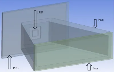
4.1.1. Description of the Navigation System C-HUD ... 58
4.1.2. Specifications of the Kinematics ... 62
4.1.3. Kinematic and Dynamic Analysis ... 66
4.2. Numerical Simulations ... 72
4.2.1. Initial Considerations ... 73
4.2.2. Software Validation ... 78
4.2.3. Simulations on the Total Assembly ... 85
4.2.4. Simulations on One Gear ... 90
4.2.5. Simulations on the Assembly of Gears ... 99
4.2.6. Comparison and Discussion of the Numerical Results ... 105
5. Experimental Validation ... 111
5.1. Description of the Experiment ... 112
5.2. Presentation of the Results ... 114
5.3. Comparison of the Numerical and Experimental Results ... 119
6. Concluding Remarks ... 129 References ... 133 Appendices ... 143 Appendix A ... 145 Appendix B ... 149 Appendix C ... 153 Appendix D ... 157
LIST OF FIGURES
Figure 1 - Bosch Car Multimedia (Bosch S.A., 2011) ... 4
Figure 2 - Types of products developed and produced at Bosch Braga (Bosch Group, 2014) .. 4
Figure 3 - Organisational Chart (Bosch Group, 2014) ... 5
Figure 4 - Primitive Gear (Branco et al., 2009) ... 13
Figure 5 - Gear Illustrations of Leonardo da Vinci (Drago, 1988) ... 13
Figure 6 - Issus Coleoptratus (Mechanical Gears Seen for the First Time in Nature, 2013) ... 15
Figure 7 - Example of Gears (Flores & Claro, 2007) ... 16
Figure 8 - Movement Transmission Systems by Intermediate Connection: (a) four bar mechanism; (b) transmission by belt; (c) transmission by chain; (Flores & Claro, 2007) ... 16
Figure 9 - (a) Rotating movement transmission for rotation; (b) Rotating movement transmission for translation (Flores & Gomes, 2015) ... 17
Figure 10 - (a) Gearing with Parallel Shafts; (b) Gearing with Concurrent Shafts; (c) Gearing with Non-Coplanar Shafts (Flores & Gomes, 2015) ... 18
Figure 11 - (a) Gears of a mixer; (b) Gears of a toy (Flores & Gomes, 2015) ... 18
Figure 12 - (a) Mechanical Watch; (b) Automobile Differential; (c) Pinion-Rack; (d) Large gear; (e) Counter; (f) Reduction Gear; (g) Industrial Mixer; (h) Manual Reduction Gear of a Car (Flores & Gomes, 2015) ... 19
Figure 13 - A two-dimensional model of a gear tooth (Cook et al., 2002) ... 31
Figure 14 - Mesh for finite volumes: (a) cell-centred; (b) cell-vertex (Moukalled et al., 2015) ... 37
Figure 15 - Axial Forces applied in a Bar (Moaveni, 1999) ... 42
Figure 16 – Tetrahedron with 4 nodes (left) and 10 nodes (centre); Hexahedron with 20 nodes (right) (ANSYS Inc., 2013) ... 47
Figure 17 - Triangle Aspect Ratio Calculation (ANSYS Inc., 2013) ... 47
Figure 18 - Aspect Ratios for Triangles (ANSYS Inc., 2013) ... 48
Figure 19 - Maximum Corner Angles for Triangles (ANSYS Inc., 2013) ... 48
Figure 20 - (a) Equilateral Triangle; (b) Highly Skewed Triangle (ANSYS Inc., 2013) ... 48
Figure 21 - Principle of Triangulation Technology (LMI Technologies, 2013) ... 56
Figure 23 – Representation of Combiner Head-Up Display (Bosch Car Multimedia, 2014) .. 59
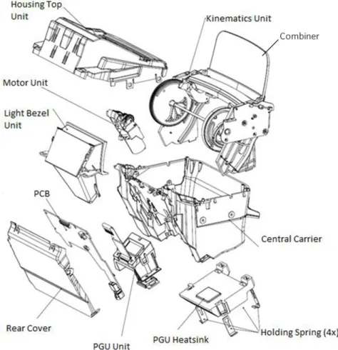
Figure 24 - Components of C-HUD (Technical Drawings of the Combiner Head-Up Display) ... 61
Figure 25 - Components of the Kinematics Module ... 62
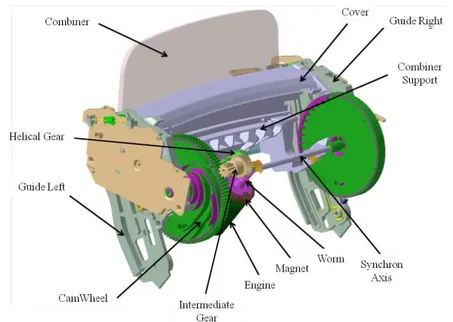
Figure 26 - Kinematics System ... 63
Figure 27 - Nomenclature of Gears ... 64
Figure 28 - Representation of the Train ... 66
Figure 29 - Lead Angle of a Worm ... 68
Figure 30 - Forces Applied on a Worm Gear (Gopinath & Mayuram) ... 68
Figure 31 - Forces Applied on Spur Gears ... 70
Figure 32 - Assembly in Study ... 74
Figure 33 - Parts of the Assembly ... 74
Figure 34 - View in Detail about Picture Generator Unit ... 75
Figure 35 - Gears of the Assembly ... 75
Figure 36 - Coupled Simulation Steady-State Thermal and Static Structural ... 79
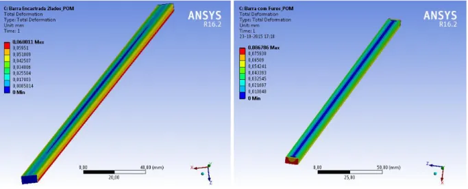
Figure 37 - Geometry and Mesh of the Bar ... 80
Figure 38 - Geometry and Mesh of the Bar with Holes ... 81
Figure 39 - Fixed Bar at both Ends ... 81
Figure 40 - Fixed Bar at both Holes ... 82
Figure 41 - Results for Bar 1 ... 82
Figure 42 - Results for Bar 2 ... 83
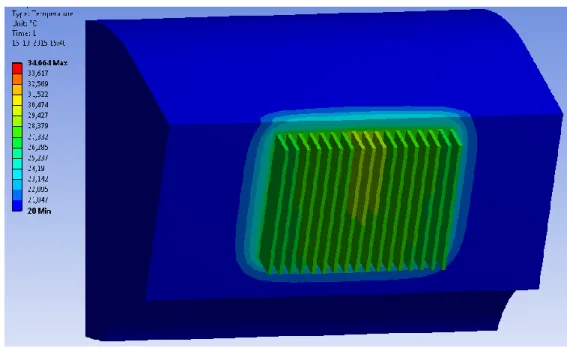
Figure 43 - Assembly in Study: (a) Outside; (b) Inside ... 85
Figure 44 - Mesh: (a) Outer Parts; (b) Inner Components ... 86
Figure 45 – Power of the LED ... 87
Figure 46 - Results of Temperature at 20 °C ... 88
Figure 47 - Temperature Distribution at 20 °C ... 88
Figure 48 - Temperature of the LED at 20 °C... 89
Figure 49 - Results for the Simulation at 90 °C ... 90
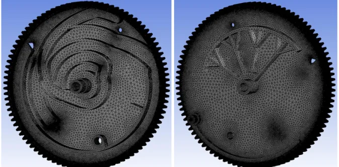
Figure 50 - Geometry of the Gear on the Front (left) and on the Back (right) ... 91
Figure 51 - Gear Mesh on the Front and on the Rear ... 91
Figure 52 – Details about the Mesh Teeth ... 92
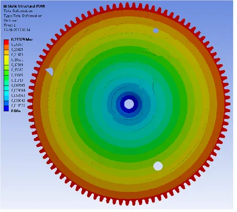
Figure 53 - Total Deformation for Material POM ... 93
Figure 54 - Total Deformation for Material PP ... 93
Figure 56 - Method of Spheres of Influence ... 95
Figure 57 - Residuals of the Simulation ... 96
Figure 58 - Temperature of the Gear ... 97
Figure 59 - Results for the material POM ... 97
Figure 60 - Results for the Material PP ... 98
Figure 61 - Representation of the Assembly Geometry ... 99
Figure 62 - Mesh of the Assembly (Front) ... 100
Figure 63 - Mesh of the Assembly (Back) ... 101
Figure 64 - Details about the Mesh ... 102
Figure 65 - Results of Total Deformation for Material POM ... 103
Figure 66 - Von-Mises Stresses for POM Simulation ... 103
Figure 67 - Results of Total Deformation for Material PP ... 104
Figure 68 - Von-Mises Stresses for PP Simulation ... 105
Figure 69 - Comparison of the Software Module ... 107
Figure 70 - Comparison of the Materials ... 107
Figure 71 - Results about Convergence of the Mesh ... 109
Figure 72 - Equipment used in the Experimental Activity (STEINBICHLER - Inspiring Innovation, s.d.) ... 112
Figure 73 - Experimental Activity of the Gear at 20 °C ... 113
Figure 74 - Experimental Activity of the Gear at 90 °C ... 114
Figure 75 - Experimental Results for the Teeth at 20 °C ... 115
Figure 76 - Experimental Results for the Teeth at 90 °C ... 116
Figure 77 - Experimental Results for the Path of the Pin at 20 °C ... 116
Figure 78 - Experimental Results for the Path of the Pin at 90 °C ... 117
Figure 79 - Experimental Results for other part of the Pin Path at 20 °C ... 117
Figure 80 - Experimental Results for other part of the Pin Path at 90 °C ... 118
Figure 81 - Experimental Results for the Angular Adjustment Component at 20 °C ... 118
Figure 82 - Experimental Results for the Angular Adjustment Component at 90 °C ... 119
Figure 83 - Teeth Displacement Results ... 120
LIST OF TABLES
Table 1 - Parameters to determine h ... 40
Table 2 - Evaluation of Mesh Quality ... 49
Table 3 - Characteristics of Gears ... 65
Table 4 - Gear Speed ... 67
Table 5 - Values for Air Density at Different Temperatures ... 76
Table 6 - Materials Properties ... 77
Table 7 - Properties of Materials ... 80
Table 8 - Comparison between Theoretical and Numerical Results ... 84
Table 9 - Results of the Radial Displacements ... 106
Table 10 - Number of Mesh Cells and Results ... 108
Table 11 - Comparison between Numerical and Experimental Teeth Results ... 120
Table 12 - Comparison of the Numerical and Experimental Path Results ... 121
Table 13 - Comparison of the Numerical and Experimental Angle Adjustment Component Results ... 122
LIST OF SYMBOLS
Latin Symbols
Symbol Description Unit
A Cross-Sectional Area mm2
B Strain-Displacement Matrix -
c Total Clearance mm
cr Radial Clearance mm
ct Transversal Clearance mm
d Nodal Displacements Vector mm
de External Diameter mm
di Internal Diameter mm
dp Primitive Diameter mm
dn Pitch Diameter of Gear n mm
e Width of Space mm
E Young’s Modulus MPa
ECV Energy in the Control Volume J
EE Constitutive Matrix Pa
fxy Coefficient of Friction between Gears x and y -
F Force N
Fa Axial Component of the Force N
FB Body Forces N/m3
FE External Body Forces Vector N/m3
Fr Radial Component of the Force N
Ft Tangential Component of the Force N
g Gravitational Acceleration m/s2
gF Fluid Acceleration Vector m/s2
Gr Grashof Number -
h̅ Average Heat Transfer Coefficient W/(m2.K)
h Heat Transfer Coefficient W/(m2.K)
Teeth (Addendum)
hf Radial Height of the Gear Teeth (Dedendum) mm
hj Heat Transfer of Species j J
i Transmission Ratio -
Jj Diffusion Flux Vector of Species j kg/(m2.s)
k Heat Flow Matrix -
keff Effective Conductivity W/(m.K)
kT Thermal Conductivity of the Fluid W/(m.K)
K Element Stiffness Matrix -
la Length of Approach mm lr Length of Recess mm L Length mm LC Characteristic Length m Nu Nusselt Number - p Pitch mm pS Static Pressure Pa P Engine Power W PA Axial Load N Pr Prandalt Number -
Q Thermal Conductance Vector W
re Nodal Loads Vector N
rx Radius of Gear x mm Ra Rayleigh Number - s Tooth Thickness mm Sh Source of Heat J Sm Source of Mass kg T Temperature °C TS Surface Temperature °C T∞ Bulk Temperature °C
𝑣 Flow Velocity Vector m/s
Greek Symbols
Symbol Description Unit
𝛼 Coefficient of Thermal Expansion K-1
𝛼𝑛 Pressure Angle °
𝛽 Lead Angle °
𝛽𝑣 Volumetric Thermal Expansion Coefficient -
𝛿 Deformation/Displacement mm 𝛿𝜀 Virtual Strains - 𝛿𝑢 Virtual Displacements m 𝜂 Efficiency - 𝜈 Kinematic Viscosity m2/s 𝜌 Fluid Density kg/m3 𝜎 Stress MPa 𝜏 Stress Tensor Pa
𝜏𝑒𝑓𝑓 Effective Stress Tensor Pa
Φ Surface Tractions Pa
ACRONYMS
2D – Two-Dimensional 3D – Three-Dimensional ANSYS – ANalysis SYStem
AR-HUD – Augmented Reality Head-Up Display CAD – Computer Aided Design
CAE – Computer Aided Engineering
CATIA – Computer-Aided Three-Dimensional Interactive Application CFD – Computational Fluid Dynamics
CFX – ANSYS Module for CFD Analysis C-HUD – Combiner Head-Up Display CM – Car Multimedia
DEFORM – Engineering Software
DFMA – Design For Manufacturing Assembly DOF – Degrees Of Freedom
END – Mechanical Development Section ENG – Engineering Department
FEA – Finite Element Analysis FEM – Finite Element Method FVM – Finite Volume Method HUD – Head-Up Display
ICCG – Incomplete Cholesky Conjugate Gradient ILC – Intelligent Light Control
ITER – Iterative Solver Option JCG – Jacobi Conjugate Gradient LCD – Liquid Crystal Display LED – Light-Emitting Diode
MUSCL – Monotone Upstream-Centred Schemes for Conservation Laws NX – Design Modelling Software
PCG – Preconditioned Conjugate Gradient PDE – Partial Differential Equations PGU – Picture Generator Unit
PISO – Pressure-Implicit with Splitting of Operators POM – PolyOxyMethylene
PP – PolyPropylene Material Reinforced with Carbon and Stainless Steel Fibres PRESTO – PREssure STaggering Option
QUICK – Quadratic Upwind Interpolation for Convective Kinematics RNG – Re-Normalisation Group
RSM – Reynolds Stress Model
SIMPLE – Semi-Implicit Method for Pressure-Linked Equations
SIMPLEC – Semi-Implicit Method for Pressure-Linked Equations Consistent SST – Shear-Stress Transport
Nelson Mandela
1. INTRODUCTION
In recent times, metal gears are being replaced by the plastic ones in a wide range of applications. This is happening due to the enhancement of their characteristics as a result of researches and studies which have accomplished new discoveries. In addition, plastics are con-trasting with metals as they are progressing whether in properties as well as processes while metals present a much higher level of development and, consequently, there are few advance-ments in this area.
On the other hand, when there is a mathematical model to be solved, the first approach is to do an analytical study where it is intended to find a solution to the set of equations. The problem is that this tends not to function when there are complicated models. For more complex models, the math becomes impossible to solve manually. Then, the alternative is to use numer-ical methods for solving the problems in study. A computer must be used to perform the thou-sands of repetitive calculations involved. The result is a gradient of what the solution is, where the applied scale allows to understand the results reached.
There is also a middle ground between these two methods. There are many important non-linear equations for which it is not possible to find an analytic solution. However, there are techniques where you can find approximate analytic solutions that are close to the true solution,
at least within a certain range.
1.1.
T
HEMEC
ONTEXT/M
OTIVATIONThe motivation to choose this theme is related with the necessity of solving a problem which appeared at Bosch through client complaints. There is a component which has been re-turned several times due to its noise of some pieces inside it. The situation is that there are only suspicions about what could be the problem. Moreover, it was defined that the company should investigate about the root of the problem in order to improve this part. Consequently, it was established to study the behaviour of plastic elements, namely gears, as they could be interfering among them at high temperatures and be causing the disturbing noise.
The use of plastics has been increasing in gears in the recent times. Plastics present di-verse advantages when compared to other metals, i.e. steel. They possess the capability to ab-sorb shocks and vibrations (Geethamma et al., 2014) as a result of their elastic compliance. It is also important to mention that they are low density and low inertia materials and produce a relatively low coefficient of friction (Subramanian et al., 2006; Lima et al., 2013). The toler-ances of polymers are, usually, less critical than for metal gears, due in part to their greater resilience (Luo et al., 2014; Huson & Maxwell, 2006). Regarding the processes, it is possible to operate with minimum or no lubrication (Pogosian et al., 2010; Hu, 1998), due to inherent lubricity and, in what concerns the production of components, they have a silent behaviour on duty. Other advantage is the fact they are resistant to corrosion which means there is no neces-sity of using plating or protective coatings. Finally, in the injection-moulding process there is a good relation between cost and effectiveness in large production.
Although plastics are favourable materials to work with, design engineers should be fa-miliar with the limitations of plastic gears relative to metal gears. Firstly, they present less ca-pacity to carry loads (Umanskii et al., 1990; Zhigun, 1991), due to lower yield and ultimate tensile strength and the greater compliance of plastic gears may also produce stress concentra-tions. Moreover, these mechanisms cannot generally be moulded having the same accuracy as high precision machined metal gears. A very critical characteristic is that plastic gears are sub-jected to greater dimensional instabilities (Gauruva & Shankar, 2015; Malkin, 2008; Ranjbaran, 2010), as they feature larger coefficient of thermal expansion and moisture absorption. Bearing that in mind, there is a reduced ability to operate at elevated (and low) temperatures which states that operations are limited to less than 120°C. In the beginning of a process, when the engineer is designing gears and intends to produce them, there is a high mould cost in developing correct
tooth form and dimensions. Lastly, if some mistake is made during the process of moulding tools or idealising the manufacturing procedure, residual internal stresses at the tooth roots can be produced resulting in over stressing and/or distortion with aging.
Considering all these motives, it is essential to study and analyse the behaviour of plastics due to its unpredictability and dimensional sensitiveness. The more engineers know about this type of materials, the best they can produce using them without the necessity of wasting money and time in errors.
1.2.
C
OMPANYP
RESENTATIONBosch company was founded in Stuttgart, Germany by Robert Bosch in 1886. He soon realised that his magneto ignition devices for automobiles had a good chance of success every-where, not only in Germany. By the year of 1898, he opened the first sales office of the company outside Germany, in London. By 1905, Bosch was already manufacturing in France, and by 1912 also in the United States. Today, the Bosch Group has some 300 manufacturing sites in over 60 countries (Bosch Group, 2014). Robert Bosch was a wise man who respected and fol-lowed his principles, such as the one it is presented below:
“I have always acted according to the principle that I would rather lose money than trust. The integrity of my promises, the belief in the value of my products and in my word of honour have always had a higher priority for me than a transitory profit.” (Robert Bosch, 1919)
The fundamentals of his thoughts and ideas are always present in everyday life at Bosch. All the processes and rules implemented in the companies are based on his convictions, which have been transmitted through generations and will continue to be passed along (Bosch S.A., 2011).
In figure 1, it can be seen the company Bosch Car Multimedia situated in Braga where most of the work for this dissertation was developed.
The Bosch Group is a leading global supplier of technology and services. The company employs approximately 360,000 associates worldwide (until April 1st, 2015), 45,700 of them
are employed in the area of research and development. Its operations are divided into four busi-ness sectors: Mobility Solutions, Industrial Technology, Consumer Goods, and Energy and Building Technology.
Figure 1 - Bosch Car Multimedia (Bosch S.A., 2011)
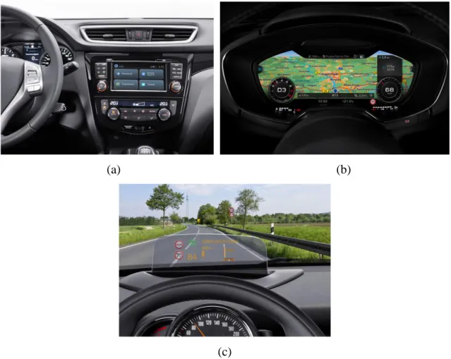
In terms of production and development of devices at Bosch Braga, they are related with system integration of complex, networked Car Multimedia systems and radio (in figure 2 (a)), entertainment, navigation, and telematics systems. More recently the company have been in-vesting in products such as premium instrument clusters (in figure 2 (b)) and head-up displays (in figure 2 (c)) since they are the future of human machine interface (Bosch Group, 2014).
(a) (b)
(c)
Figure 2 - Types of products developed and produced at Bosch Braga (Bosch Group, 2014)
forefront of technology.
The author of this dissertation was integrated in the mechanical development section (END), which was created in 2002, where the components are designed using softwares such as NX 7.5 and CATIA and structurally analysed with ANSYS. Nowadays, it is increasingly more important to simulate the processes to be aware of possible failures and, thus, saving money in prototypes. Along the fulfilling of their tasks, it is also important to communicate with the clients to ensure that all the requirements and standards are being followed.
This section has also the role of holding and moderating DFMA (design for manufactur-ing assembly) for all the projects in which it is discussed and decided the more suitable pro-cesses to produce and assemble the components. The DFMA coordinator has also the function of following the changes and progresses of the different activities. These are some of the roles that this section has to perform along with cost analysis and benchmarking tasks in every pro-ject.
In figure 3, it is presented an organisational chart of the engineering department.
In every section there are projects in course of the types of products previously referred. The main goal of department’s head is that Bosch Braga becomes an independent company, in which, a product can be fully developed and produced in the same place. For that purpose, it is essential that Braga keeps investing in research of all areas with the view to possess knowledge in the various fields of product development, from the very beginning until the end of the whole process (Bosch Group, 2014).
Figure 3 - Organisational Chart (Bosch Group, 2014)
In conclusion, the strategic objective of Bosch Group is to create solutions for a connected world. Bosch improves quality of life worldwide with products and services that are innovative
and create enthusiasm. In short, Bosch creates technology that is “Invented for life”.
1.3.
O
BJECTIVESThere are several objectives expected to be accomplished by the end of this project which will be described in this part.
As it was referred in the previous section, there is a problem to be solved, a situation to be investigated which constitutes one of the primary goals to achieve. The interference of the components is a real possibility as, in certain circumstances, these pieces can reach high tem-peratures. Moreover, it is intended to analyse the behaviour of specific divisions of the ele-ments, namely the contact of gear teeth and a path that must be followed by a pin of other component. If these features expand or contract, or continue working with some restrictions or limitations, it may threaten the correct function of the whole mechanism.
Another fundamental subject to study is the behaviour of polymeric materials, which con-stitutes a consequence of what was mentioned early. There are other types of materials to be examined, including some which could be alternatives to the ones being used. It is also intended to evaluate, based on the results of the simulations, if the tolerances applied to the gears are ranged between appropriate limits.
In the course of this project, it is expected for the author to develop skills regarding the software, its possibilities, and the types of analyses provided as well as enhance knowledge about the heat transfer field.
1.4.
W
ORKM
ETHODOLOGYThe work developed to this dissertation followed some methodologies which will be pre-sented in this section. It is important to define strategies to achieve the proposed objectives and organise what needs to be done.
In the beginning of this work was performed some research of articles in order to under-stand the approaches of different people to thermal simulations as well as structural ones. The websites used was mainly Science Direct, Taylor and Francis and Springer. This inspection focused, mainly, on gears but also in other types of systems which are recurrently submitted to high temperatures and, because of that, their performance can be affected.
Next, the mechanisms it is intended to study were analysed in detail due to the importance of understanding how they function. To do so, they were examined some drawings of the com-ponents as well as the datasheets of the constitutive parts.
It was necessary to design the studied components and the chosen software was NX v7.5 (NX, 2015) as it is the one used for most of the employees of engineering section. Regarding the thermal and structural simulations, the adopted software was ANSYS v16.0 (ANSYS, 2015) due to its possibilities to implement the types of boundary conditions required in the problems and the diverse solvers it could be used to analyse the situations.
To perform the simulations it was mandatory to search for information about the possi-bilities of the software and how these features could be implemented. The website of ANSYS provides guides for the different modules including all the pertinent knowledge it is important to know including possible loads to be applied, diverse solvers and, most importantly, what types of solutions it is possible to obtain in each analysis. The tutorials available on this website are also very useful, whether in text or in video where it is explained every step of the studies.
There were consulted some books as well with the purpose of understanding and clarify-ing some definitions and processes about heat transfer, mechanical phenomena, gears and its operation, among other examples. It is crucial to support the work with the knowledge of books as they are, probably, the most reliable source of information there is.
1.5.
O
VERVIEW OFD
ISSERTATIONC
ONTENTThis master dissertation is constituted by 6 chapters where will be detailed all the work and progresses which have been achieved for the last months. The background, the considera-tions, the decisions, the producconsidera-tions, the results will be described and explained for the next sections.
In the first chapter is presented introductory information related with generally instruc-tions. The scope and motivation of the theme are explained as well as the company presentation where this dissertation was developed. Moreover, the objectives which are intended to reach are covered and the methodology followed to search for theory, to simulate, to conclude is also summarised in this section. Finally, it is focused on the structure of the dissertation in order to present the approached subjects.
The second segment deals with the background of the problem in which it is divided in 2 parts: technical and technological component. The first includes a brief history and some facts about gears as well as the reasons for the importance of having this type of mechanisms in our quotidian. It is also incorporated a few examples of applications of these systems in industry. The second portion summarises what has been performed on gears in the field of the thermal simulations and some cases of coupled analyses of thermal and structural studies produced on
components are displayed.
The third division covers the theoretical themes it is necessary to be intensely explained so that the reader can understand everything it is presented in the next parts. Firstly, there are the methods which the modules of ANSYS are based on and the details about how they are structured. Secondly, there are the descriptions of the heat and mechanical phenomena and of the physical features that constitute the outcomes of the simulations. Then, it is discussed the mesh, where the implemented methods and elements used are described. Consequently, the solvers of the different types of simulation are clearly explained with all the equations involved. Finally, some experimental technologies are described highlighting the one used to produce the experimental activities of this work.
The forth part regards the presentation of the studied components, detailing its specifica-tions and main characteristics. It is displayed the results of 2 analyses completed on the assem-bly of gears: a kinematic and a dynamic. It is important to investigate the mechanism in order to clarify under what conditions it functions. Consequently, there are the simulations performed on the pieces. Some are purely thermal and others are coupled, which means, a thermal and a structural study are joined in order to inspect the stresses of the gear teeth. At the end of this section, some results are compared highlighting the similarities and differences between them. Regarding the fifth chapter, it is about the experimental activities which were executed at the metrology laboratory of Bosch. It starts with the description of what was done during the experiments and, then, the results are displayed for the various parts analysed. Consequently, the numerical and experimental results are compared and some conclusions are drawn. Finally, some recommendations are made considering the experimental results and the tolerances adopted for the diverse parts.
In the last section, it will be written some concluding remarks about the whole work as well as ideas will be presented for future work which could be developed having what is incor-porated in these chapters as the basis.
Finally, there are some appendices which consists of documents used to check infor-mation used on parts and it is necessary to show them, although they are not truly essential to be included in the main segment of this report.
Cristóvão Colombo
2. BACKGROUND
This chapter congregates information about different types of transmission mechanisms although gears are the ones discussed more in detail since it is the crucial system of this work. It is fundamental to describe certain aspects for the readers to have the appropriate background in order to understand the decisions drawn during the project. The general characteristics, the main advantages and disadvantages of these systems are explained in which shafts, couplings, chain and belt drives are approached.
The strength of a shaft is only one of the considerations for its design. It must also be rigid enough to minimise deflection and must have sufficient angular and torsional stiffness to avoid vibratory movement. There are several different types of shafting. Power transmission shafting is usually round, either solid or tubular. For some small equipment, the shafting may be square or rectangular. This type of shafting is used to facilitate connecting; a matting part with a square or rectangle bore is used. This type of shaft is also used where length compensa-tion may be required (Internacompensa-tional Organisacompensa-tion for Standardisacompensa-tion, 1988; South & Mancuso, 1994).
of rotating equipment. There are two basic classes of couplings: rigid and flexible. Rigid cou-plings should only be used when the connecting structures and equipment are rigid enough so that very little misalignment can occur and the equipment is strong enough to accept the gener-ated moments and forces. There are hundreds of types of flexible couplings, in which the most common are gear couplings, grid couplings, chain couplings, elastomeric shear couplings, elas-tomeric compression couplings, disk couplings, diaphragm couplings. Flexible couplings ex-pand the basic function by accommodating misalignment and end movement. During the initial assembly and installation of rotating equipment, precise alignment of the equipment shaft axes is difficult to achieve. In operation, this can be caused by flexure of structures under load, set-tling of foundations, thermal expansion of equipment and their supporting structures, piping expansion or contraction, and many other factors. A flexible coupling is used to compensate for or minimise the effects of misalignment. (South & Mancuso, 1994; Chironis & Sclater, 1996)
Chains are manufactured to various degrees of precision ranging from unfinished castings or forgings to chains having certain accurately machined parts. It may be stated that a chain, composed of a series of links pinned together, is a form of flexible gear connecting two toothed sprocket wheels mounted on parallel shafts. Their main advantages are having the same flexi-bility as belts, the excellent design flexiflexi-bility they provide as well as convenience, and re-sistance to shock loading. Also, they operate satisfactorily in adverse surroundings, they can be manufactured in various special steels to resist specific environments, and they have unlimited shelf life, simplicity of installation and general economy. Mechanical efficiency, in comparison to gear and belt drives, is favourable. In other words, chains operating under ideal conditions can have efficiencies as high as 97 to 99 %. There are 3 principal types of chains: roller, silent, and engineering steel. In terms of applications, their major uses are: power transmission drives, conveyors, bucket elevators and tension linkages. (International Organisation for Standardisation, 1988)
Belts have many advantages over other power transmission mechanisms. One of the most important is overall economics. The efficiency and reliability of belts as a power transmission method is well recognised. Belts are clean and require no lubrication. They can transmit power between shafts spaced widely apart with a wide selection of speed ratios. Belts can be used for special design purposes such as clutching, speed variation and transmitting power in more than one plane. They are also capable of handling large load fluctuations and have excellent shock-absorbing abilities. Belts have an extremely broad application range (torque, speed, ambient conditions, etc.) that make them ideal for virtually any application. They have gained wide usage mainly due to lack of lubrication requirements, and very high power density of modern
curvilinear belts. (South & Mancuso, 1994)
Gears are used to transmit power positively from one shaft to another by means of suc-cessfully engaging teeth (in two gears). They are preferred over other alternatives when exact speed ratios and power transmission must be maintained. Gears may also be used to increase or decrease the speed of the driven shaft, thus decreasing or increasing the torque of the driven number. There are several types of gears such as spur, bevel, helical, worms, rack and pinion among others and, some of them, can be internal or external.
Gears and gear systems have been fundamental machine components which contributed to an evolution of machinery efficiency and capability. Technological evolution of gear systems has been supported also by a constant research developed throughout the years which resulted in the publication of many books. Some of them are enumerated as they contribute, somehow, to the development of this dissertation. Regarding the history of gears and the major contribu-tions to this field, the books A History of the Machine by Strandh (1979) and A Gear Chronol-ogy: Significant Events and Dates Affecting Gear Development by Crosher (2014) were pub-lished. Concerning the design, the kinematic and dynamic movements of gears, the number of existing books is enormous. In 1903 it was published the Kinematics of Machines (Durley) and the French Henriot wrote The Theoretical and Practical Treaty of Gears (1979). These books are very helpful to clarify some singularities about gears which are important to analyse. There is also the Mechanisms and Dynamics of Machinery by Mabie and Reinholtz (1987), followed by the publication of the book Fundamentals of Gear Design by Drago (1988) and in 1989 the compilation Mechanical Engineering Design by Shigley and Mischke (1989) emerged which is considered as one of the most outstanding books to learn about gears.
In the 20th century several publication appeared namely, Kinematics and Dynamics of Machinery by Wilson and Sadler (1993), Theory of Machines and Mechanisms by Shigley and Uicker (1995) and Design of Machine Elements by Spotts and Shoup (1998). These books are essential to study and investigate the movement as well as the forces involved in the mechanism in study.
More recently, the book Fundamentals of Machine Component Design was published in 2006 (Juvinall & Marshek), along with The Kinematic of Mechanisms by Flores and Claro (2007) and Applied Mechanics – A Practical Approach published in 2012 (Antunes) was also publicised. All these manuals are important to be consulted when some doubt appears related to gears.
As gears are a type of mechanism usually used in several contexts, they present much diversified applications. There are examples of automotive industry (Hwang & Huang, 2011;
Kadmiri et al., 2012; Haj-Fraj & Pfeiffer, 2001; Meng et al., 2015; Lingamanaik & Chen, 2012), aeronautical industry (Wen et al., 2009; Savaria et al., 2015; Heyns et al., 2012; Stander et al., 2002), the aviation industry (Wang et al., 2008; Gualdi et al., 2008; Ossa, 2006; Lee et al., 2003; Bagnoli et al., 2008; Khapane, 2006) and the wind turbines (Qiu et al., 2015; Nejad et al., 2014; Fernandes et al., 2015; Fernandes et al., 2014). In these fields, the systems are mostly respon-sible for the transmission of movement which, consequently, causes the displacement of the parts and the locomotion. However, it is also crucial to investigate alternative materials, main-taining the same characteristics, which could be used in these applications and some examples can be found in the following articles (Zhou et al., 2013; Mao et al., 2009; Kurokawa et al., 2003; Düzcükoglu, 2009; Yakut et al., 2009; Hoskins et al., 2014).
There are various softwares in the market which are capable to perform simulations of assorted types since static, dynamic, and thermal analysis across the linear and nonlinear do-mains. Some examples are ANSYS (ANSYS, 2015), Abaqus (Abaqus, 2015), Nastran (MSC Nastran, 2015), Algor (Algor, 2011) and SolidWorks (SolidWorks, 2015). They present differ-ent levels of accuracy for the individual modules although they are able to execute all kinds of simulations. Then, there is the software DEFORM (DEFORM, 2015) which is used to analyse metal forming, heat treatment, machining and mechanical joining processes. This programme has proven itself to be extremely effective in a wide range of research and industrial applica-tions. Lastly, there is the FloTHERM (FloTHERM, 2015) which is a software to perform ther-mal analyses, create virtual models and test design modifications of electronic equipment mostly before physical prototyping. It is capable of considering different situations and appli-cations, dimensions and materials as well as optimising the processes.
2.1.
T
ECHNICALC
OMPONENTThis section is constituted by the description of the history about gears, highlighting the most important aspects, which happened along time. It also explains why it is fundamental to have gears in our society and what the advantages of their incorporation in other systems are. Then, it is detailed various types of transmissions as well as some types of gears. Finally, there are some examples of applications in industry referring the reasons why engineers should, from now on, adopt more polymeric gears in their applications.
2.1.1. The History of Gears and Its Importance in the Quotidian
Around the year of 1700 b.C. it emerges, in poems of literature Hindu, references of cars and wheels. Gears are also mentioned in the work of Aristoteles (384-322) as well as of Arquimedes (287-212).
The primitive gears were initially used by the Chinese people in the 3rd century b.C. and it is represented an example of one in figure 4. Nowadays this type of wheel is still being in-corporated in systems of water lifting, which are commonly called of “norias” (Branco et al., 2009). Wheels of this kind are also being used on mills.
Figure 4 - Primitive Gear (Branco et al., 2009)
The primitive gears were very rudimentary as they were constituted by pieces of wood which were inserted in a disc or in a wheel. The important fact is that they had to be consisted of some material easily workable so it could be possible to draw the shape of the teeth. Later, around the 15th century, the Italian Leonardo da Vinci presents several illustrations where it could be identified gear arrangements, which can be seen in figure 5.
Nowadays, the most frequent materials used to construct gears are low carbon steel, stain-less steel, and nodular cast iron, bronze and polymeric materials.
Until the 16th century, gears were manually fabricated and its final shape was obtained
more by accident than as a result of a study or intensive planning. The first machine able to manufacture gears was developed by the Spanish Juanelo Turriano (1501-1585), which was specially fabricated to facilitate the construction of a mechanical watch to the king Carlos V of Spain (Vera, 1996). The watch included approximately 2000 gears. In fact, the field which more significantly contribute to the development of gears was horology. The Italian Giovanni Dondi (1348-1364) was responsible for designing the first mechanical watch, for which there are only some basic design layouts known. Gears are, therefore, the type of mechanical transmission with greater practical application as they are pieces of machines which guide movement from a shaft to a driven shaft, through the use of teeth which successively contact with each other.
The industrial revolution, which happened around the century XVIII, changed the way gears were manufactured at that time as they started to be fabricated with metallic materials. Due to this development, gears presented higher durability and load capacity. In the beginning of the 19th century, the industry of gear production was already as we know it nowadays, in which the profiles of the teeth obeyed to curves previously defined such as the cycloid or the involute (Flores, 2009). Among the most important names of people who significantly contrib-ute to the study and development of gears, it could be highlighted Girolamo Cardano, Robert Willis and Wilfred Lewis. Other authors could be included, however, the ones mentioned above summarise the most essential improvements (Drago, 1988). Girolamo Cardano established the first mathematical models for gears in 1525 while Robert Willis leaded several studies related to gears as well as trains of gears.
Presently, the new progresses in the scientific and technical area of gears are associated with new materials, new manufacturing techniques and the advanced methodologies of design, simulation and optimisation of gears in addition to the extensive use of electronics (Li et al., 2014; Denkena et al., 2014; Simon, 2014).
Although people think they had invented gears, in 2013 Malcolm Burrows and Gregory Sutton performed a study which discovered that it was nature the first to create and implement gears on animals. Until recent times, it was assumed that the mechanical gear was invented around 300 B.C. by Greek mechanics who lived in Alexandria. The fact is that it might not be true, as a small hopping insect called Issus Coleoptratus, whose existence dates before that, uses toothed gears to precisely synchronize the impulses of its hind legs in order to jump forward.
anatomic structure of the three-millimetre long insect and revealed that only the juveniles of the species possess a complex system, located in the posterior part of its body, similar to a gearing system which allows them to jump forward. This mechanism is extremely important for the insect to move straight forward as the legs are locked together and they rotate at the exact same time. In order to prevent being off course, the existence of this system of gears is fundamental or otherwise, there is the possibility of one leg be extended a fraction of second earlier than the other.
This discovery is believed to be the first functional gearing system ever discovered in nature, although there have been previously found another systems resembled with gears in other animals. However, these mechanisms did not contribute for the animal’s life in any way which proved they did not have any function.
It is important to refer that this is the primal natural system that mechanically functions like gears as we know them. They represent the highest level of machinery which evolved in animal structure to be possible its synchronisation of movement (Mechanical Gears Seen for the First Time in Nature, 2013).
The animal called Issus Coleoptratus as well as the gearing system are presented in figure 6.
Figure 6 - Issus Coleoptratus (Mechanical Gears Seen for the First Time in Nature, 2013)
2.1.2. The Application of Gears in Industry
In mechanisms, the transmission or transformation of movement can be executed in 2 distinct ways, namely by direct contact (figure 7) or by an intermediate connection (figure 8) (Flores & Claro, 2007). In the first case, the movement is promoted through the contact between surfaces of the driver and driven organs. Gears can be included in the first group, such as the ones it can be seen in figure 7.
Figure 7 - Example of Gears (Flores & Claro, 2007)
On the other hand, the second group is constituted by systems in which the transmission of movement between the motor and the moved components is promoted by a medium body. When there is a third body involved, the connection can be rigid, as in the case of a 4 bar mechanism, or flexible, such as in belts and chains.
Figure 8 illustrates these 3 types of transmission using an intermediate connection, which were previously explained (Flores & Claro, 2007).
(a) (b) (c)
Figure 8 - Movement Transmission Systems by Intermediate Connection: (a) four bar mechanism; (b)
transmis-sion by belt; (c) transmistransmis-sion by chain; (Flores & Claro, 2007)
The principal characteristic of gears is the fact they allow the transmission of movement between bodies with a constant relation. In addition, the transmission ratio can be defined as the quotient of the rotation velocities of 2 bodies where there is a progression of mobility from one to the other. Furthermore, a gearing system is a mechanism composed by 2 rigid wheels with teeth which conduct locomotion between distant axes, or they could also be used when there is the need of reducing or increasing the velocity or the moment of the motor shaft. In these mechanical organs, the movement is transferred by the driver’s gear teeth, which roll without slipping, over the teeth of the driven gear. The smallest wheel, and consequently the one with a lower number of teeth is called of pinion. On the other hand, the wheel of bigger dimensions is simply denominated of gear. These designations have nothing to do with the fact that they are the driver or the driven body, the only important aspect is the dimensions of the gears (Henriot, 1979).
of other body, as it is shown in figure 9.
(a) (b)
Figure 9 - (a) Rotating movement transmission for rotation; (b) Rotating movement transmission for translation
(Flores & Gomes, 2015)
Among the several systems of transmission of rotating movement, gears are very versatile bodies. In fact, the use of gears enables the transmission of movement between parallel or non-parallel shafts. Moreover, these components are also adaptable in cases it is necessary to operate mechanical systems of low and high number of rotations. In general, gears present an efficiency considerably large (until 99 %), expect worms which manifest efficiencies relatively low (about 45-70 %) due to the elevated slipping that happen in this type of gear (Niemann, 1971).
There are other particularities which turn gears into such a useful and unique type of transmission, such as:
The extensive capacity of resistance to overloads;
The high precision in transmitting movement;
The constant ratio of transmission and independent from the applied charges;
The good reliability and durability;
The ability of conducting movement from low to high powers;
The possibility for the components to have small dimensions.
One of the most significant examples related to the compactness of gears can be observed in mechanical watches, in which, in a very small space, it is possible to obtain very large ratios of transmission. It is also important to refer the excellent performance of gears, where it should be highlighted the quantity of thousands of kilometres that the automobile differentials provide without having the necessity of being repaired or substituted (Wilson & Sadler, 1993).
Apart from all these relevant aspects, gears can be manufactured using diverse materials, such as metals and polymers. However, as gears are constituted by rigid bodies, they do not absorb shocks and need to be lubricated. In addition, they are relatively expensive and noisy
and, can be affected, in their performance, by the environmental conditions such as humidity and dirt. Finally, it is essential to mention that gears can be used to transmit movement between parallel shafts, concurrent or non-coplanar, as it is exemplified in figure 10.
(a) (b) (c)
Figure 10 - (a) Gearing with Parallel Shafts; (b) Gearing with Concurrent Shafts; (c) Gearing with
Non-Copla-nar Shafts (Flores & Gomes, 2015)
The principal manufacturing processes of metallic gears are machining, sintering, casting and forming. In general, these procedures require posterior superficial finishes. In contrast, pol-ymeric gears are obtained through the process of injection. This type of gears present several advantages, namely the low weight and its reduced cost. This last aspect is particularly signifi-cant when it comes to large series of production. Polymeric gears have, however, a lower load capacity and they are mainly used in smaller mechanical systems, such as, home appliances and toys. Figure 11 shows this type of gears being used in the referred applications.
(a) (b)
Figure 11 - (a) Gears of a mixer; (b) Gears of a toy (Flores & Gomes, 2015)
It is vast and very diversified the field of application of gears. In figure 12, there are various examples, such as, a mechanical watch, an automobile differential, a pinion-rack used in mountain trains, a gear used in a large machine (applied, for example, in the cement industry), a counter, a reduction gear, an industrial mixer and a manual reduction gear used in a car.
(a) (b) (c) (d) (e) (f) (g) (h)
Figure 12 - (a) Mechanical Watch; (b) Automobile Differential; (c) Pinion-Rack; (d) Large gear; (e) Counter; (f)
Reduction Gear; (g) Industrial Mixer; (h) Manual Reduction Gear of a Car (Flores & Gomes, 2015)
over the polymeric materials. However, this last field is being developed everyday which means there is so much that can be discovered about the capabilities of polymers and their abilities to attend what society need. Plastic suppliers offer numerous plastic gear with a low coefficient of friction and the strength, stiffness, fatigue, and wear–resistance characteristics that designers can take advantage of to optimize their gear tooth geometry. Designers have developed gears for many applications, such as:
• Automotive actuators (power seats, window lifts, mirrors, ignition, parking brakes, latches, closures);
• Large and small appliances (vacuum cleaners, washing machine transmissions, food processors);
• Industrial (power tools, conveying line rollers, water and gas meters); • Electronics (printers, copiers, scanners, audio and video equipment); • Medical dispensing devices;
• Garden (irrigation sprinklers, mowers, sweepers, blowers, fertilizer spreaders, swim-ming pool equipment).
The design freedom inherent in moulding plastic allows more–efficient gear geometries than it is possible using metal. Moulding can create shapes that are hard to form at a reasonable price in metal, such as internal, cluster, and worm gears. Plastic gears can have a wider aspect ratio than the ones of metal, thus increasing their load–bearing capacity and power density. Plastics have also become essential in the ongoing demand for quieter drives, which requires for high precision, new tooth shapes or flexible materials.
Gears made of plastic typically permit a 50 to 90 % cost reduction in comparison with machined metal gears, as they are usually produced in large quantities, depending on their pre-cision requirements, and they usually expect no superficial finishing. They weigh less than metal gears, and their relative inertness means they can be used in situations that cause metal gears to corrode or degrade.
Plastic is a more compliant material than metal which makes it simpler to work with in certain situations. Not only do they deflect easier, which allows them to absorb impact loads and better distribute localized loads caused by misalignment, they have lower hardness that helps disguise certain tooth errors. The inherent lubricity of many plastics makes them ideal for computer printers, toys, and other low–load situations where external lubricants are excluded. In addition to use in dry gears, plastics can be lubricated by grease or oil.
Dimensional stability, however, is a complex factor. Polymers that absorb water or chem-icals will have more dimensional variation. Temperature changes will also have an effect on
part dimensions. If they are moulded in an incorrect manner, geometry can change as the gear cools after moulding and be deformed by the working environment and friction. That is why it is so important to study the behaviour of plastics when they are in the presence of heat, humidity and other external factors. The more people know about this type of materials, the more it can be predicted during the production of pieces. If the engineers are aware of the time where failure can happen, measures can be implemented or the processes can be changed in order to avoid problems. Besides these negative aspects, polymers have been increasingly used in a variety of products as they present various advantages in comparison to metallic materials (Childs, 2013).
2.2.
T
ECHNOLOGICALC
OMPONENTIn this segment there are some examples of articles which were written having gears as the component of study. The first part deals only with thermal simulations and the outcomes are related to temperatures or heat. The second part summarises coupled thermal-structural sim-ulations applied to different components and the objectives of the studies are diversified.
It is crucial to investigate what has been done in this field as this can help establish some conditions in the analysis and by reading this type of publications, some errors can be avoided. Other important aspect is to detail the capabilities of this type of analysis.
2.2.1. Thermal Simulations Performed on Gears
To introduce this section, it is important to refer that some articles cover analyses per-formed on softwares while others develop their own numerical studies and other researchers even take an existing model and simplify it or adapt to other situations. It is quite often to compare the obtained results to the outcomes of experiments or of a previous analytical or nu-merical model in order to validate what has been executed.
Some researchers built a model with a deforming mesh, which means the mesh is being replaced along the simulation, to study a turbulent flow in the section chamber of a gear pump, using ANSYS Fluent (Castilla et al., 2010). The mesh replacement strategy is adopted in order to avoid skewed meshes and allow for simulation of solid contact between gears. Several mod-els were tested and all of them failed in some respect although the solvers RSM and RNG k-epsilon were the best choices. This data was, consequently, compared with experimental results.
Other investigators studied the distortions of bevel gears due to heat treatment using a software named DEFORM (Cho et al., 2004). The distortions of forged and machined gears are measured and compared. This analysis is used to simulate the complete heat treatment process
for the machined gears and the results showed good agreement with the experimental measure-ments. The analysis concluded that the deviations are larger in the forged gears, specifically in the outer diameter and in the tooth width were almost doubled.
Stark and his colleagues (2013) used the software DEFORM to perform their study of heat flux and temperature distribution in gear hobbing operations. Firstly, they evaluated the generated heat during chip formation and, then, used these results to perform a heat flow simu-lation. The objective is to calculate the heat flow of the process and the thermal deviations. The results showed a good agreement between the measured and calculated temperature fields in chip formation and heat flow.
Other authors have decided to present equations for calculating bulk temperature as well as critical temperature of a lubricant/steel combination based on gear scuffing results obtained on a high speed gear teste rig (Jiang & Barber, 2000). Critical scuffing temperature, previously thought to be independent of operating conditions, is found to be greatly influenced by gear speed and oil type. Experiments show that synthetic oils increase the value of critical tempera-ture dramatically in comparison with base mineral oils, and speed also alters this temperatempera-ture. This paper presents a modified equation for converting scuffing load limit between simulated and practically used gears.
One other article describes a numerical method of the flash temperature for polymer com-posite gears and the heat partition between gear teeth (Mao, 2007). The problem is treated as an unsteady one where the intensity distribution and velocity of heat source changes as meshing proceeds. A numerical approximation is adopted using finite difference method and the results are shown to be similar of those found using semi-analytical method. Moreover, it is shown that the solution of Blok (1937) can be used to provide a quasi-steady approximation that is for mean flash temperature estimation. However, in other circumstances, the Blok’s solution is inaccurate and the current approach should be used.
Atan with a co-author (2005) simplified a model (Seireg & Atan, 2002) and, conse-quently, executed a comparison between the interpretation they had developed and the previous formulation. These researchers used existing data to establish an artificial intelligence model where a multi layer feedforward neural network has been employed. The model accepts surface roughness, gear ratio, horsepower and the number of teeth as input variables, and as outputs the calculated pinion surface asperity temperatures. The aim of this work is to provide a straight-forward and simple way to compute the asperity temperature rise for a given set of variables. The analytical method requires many iterations between the viscosity and the temperature, and though the iterations, many data has to be entered by hand. In the more recent method, none of