BJRS
RADIATION SCIENCES
06-02-A (2018) 01-14Acepted : 2018-06-06
Performance tests of a special ionization chamber for
X-rays in mammography energy range
J. O. Silva
aand L. V. E. Caldas
ba Universidade Federal de Goiás/Instituto de Física, Campus Samambaia, Goiânia, Brazil
b Instituto de Pesquisas Energéticas e Nucleares (IPEN-CNEN/SP)/Gerência de Metrologia das Radiações, São Paulo,
Brazil [email protected]
ABSTRACT
A special mammography homemade ionization chamber was developed to be applied for mammography energy range dosimetry. This chamber has a total sensitive volume of 6 cm³ and is made of a PMMA body and graphite coated collecting electrode. Performance tests as saturation, ion collection efficiency, linearity of chamber response versus air kerma rate and energy dependence were determined. The results obtained with this special homemade ionization chamber are within the limits stated in international recommendations. This chamber can be used in quality control programs of mammography energy range. All measurements were carried out at the Calibration Laboratory of IPEN.
1. INTRODUCTION
Breast screening with X-rays is the choice option for early detection of breast cancer, and it is largely applied in many countries as Brazil. The diagnostic effectiveness and reliability depends on the quality control program of the mammography equipment, which involves an accurate dosimetry [1,2]. Therefore, the dosimetry procedures of the X-ray equipment should be performed with relia-ble ionizing radiation detectors as ionization chambers. For quality control in medical clinic X-ray equipment, ionization chambers are the reference detectors for the routine verification of the dosi-metric parameters as air kerma rate [3]. So, this kind of detector has to follow high quality control standards and be calibrated in well-known standard radiation fields. In Brazil, ionization chambers for clinical dosimetry and calibration laboratory applications have been developed and presented high metrological levels [4-7]. These ionization chambers were made with low cost materials, and among these ionization chambers, mammography chambers were assembled to be utilized in mam-mography energy range radiation beams.
In this work, an ionization chamber is presented for dosimetry in mammography beams. This ionization chamber, called special ionization chamber, is made of a plastic material and has a thickness of 2 cm, which is adequate for radiation dosimetry in mammography phantoms with 2 cm in thickness [8]. Furthermore, the special ionization chamber has a sensitive volume of 6.0 cm³. This ionization chamber was characterized with respect to various performance tests: saturation of ionization current, ion collection efficiency, polarity effect, stabilization time, linearity of the response, directional and energy dependences.
2. MATERIALS AND METHODS
The special ionization chamber has a total sensitive volume of 6.0 cm³ (two sensitive volumes of 3.0 cm³) and a distance of 4 mm between the inner electrodes. Ionization chambers with double sensitive volume have been developed for other beam radiation qualities [4,9], but not for mam-mography energy range yet. A picture and a drawing of this special ionization chamber are present-ed in Figure 1.
Figure 1: (a) The special ionization chamber and (b) a detailed drawing of it
The chamber body is made of Polymethyl metacrilate (PMMA). For charge collection and elec-tric field uniformity in both sensitive volumes, the collecting electrode and the guard ring are made with a graphite coating of around 0.35 μm, located in both sides of the same thin plastic film, as presented in Figure 2.
Figure 2: The collecting electrode and guard ring arrangement within the special ionization
chamber
To establish the electric field, aluminized polyester with 1.87 mg.cm-2 of superficial density was utilized for the entrance window; this material was used in the inferior region of the total
sensi-tive volume at the same high voltage value. A PTW-Freiburg UNIDOS electrometer was utilized to polarize and to take the readings of the special ionization chamber. Coaxial cables and BNC con-nectors were used for the electrical connection between the ionization chamber and the electrome-ter.
To perform the measurements, the ionization chamber was exposed to radiation beams from a Pantak Seifert Isovolt 160HS X-ray equipment with tungsten target, which operates from 5 kV to 160 kV (the current can vary from 0.1 mA to 45 mA) with an inherent filtration of 0.8 mmBe and from a PTW 90Sr +90Y (33 MBq, 1994) control source, 8921 type. These irradiation systems are located at the Calibration Laboratory (LCI) at IPEN. The PTB WMV (for direct beams) and WMH (for attenuated beams) mammography qualities [10] utilized in this work were established previous-ly at LCI, and they are described in Table 1. As the special ionization chamber is not sealed, correc-tions in the readings were necessary for the standard environmental condicorrec-tions (20 °C and 101.3 kPa).
Table 1: PTB mammography radiation qualities implemented at LCI. Molybdenum and al-uminium additional filtrations.
Radiation quality Tube voltage (kV) Tube current (mA) Additional filtration Half-value layer (mmAl) Air-kerma rate (mGy/min) (mmAl) (mmMo) Direct beams WMV 25 25 10 --- 0.07 0.36 9.56 WMV 28 28 10 --- 0.07 0.37 11.94 WMV 30 30 10 --- 0.07 0.38 13.48 WMV 35 35 10 --- 0.07 0.41 17.53 Attenuated beams WMH 25 25 10 2.00 0.07 0.56 0.46 WMH 28 28 10 2.00 0.07 0.61 0.66 WMH 30 30 10 2.00 0.07 0.68 0.83 WMH 35 35 10 2.00 0.07 0.93 1.46
3. RESULTS AND DISCUSSION
In this section the findings about the performance of the special ionization chamber will be presented and described. They are organized in subsections: the saturation curve, the ion collection efficiency, the polarity effects, the linearity of response, the stabilization time, the directional dependence and the energy dependence.
3.1. Saturation curve
To perform the saturation test, the entrance window was located at the reference distance of 100 cm in relation to the X-ray reference point. The ionization chamber was irradiated in the WMV 28 radiation quality, as presented in Table 1, and it was polarized with ± 50 V to ± 300 V in steps of ± 50 V. The saturation curve is shown in Figure 3. The ionization currents were determined as mean values of ten measurements for each voltage value. The uncertainties in the ionization currents were always less than 0.05% for both polarities. It can be seen that the ionization current is constant starting at ± 50 V, and it presents a symmetrical behavior when a change in the polarity signal occurs.
Figure 3: The special ionization chamber saturation curve. As the uncertainties were less
3.2. Ion collection efficiency
The ion collection efficiency, ks, was determined by the two-voltage method (IAEA, 2000)
us-ing the results obtained for the saturation curve:
1 2
2 2 1 2 2 1 / / 1 / M M V V V V = ks (1)where M1 and M2 are the electrometer measurements corrected for the influence of temperature and
pressure, at voltages V1 and V2 and V1 = 2V2 [11]. The voltage V1 is the value normally used for
these chambers, and in this case it was ± 300 V. For the ionization chamber, the ion collection efficiency is better than 0.9994 for the positive polarity and 0.9995 for the negative polarity. It can be seen that the special ionization chamber presents ion collection efficiency better than 99.9%; therefore, the recombination losses are lower than 1.0% as recommended by IEC [12].
3.3. Polarity effects
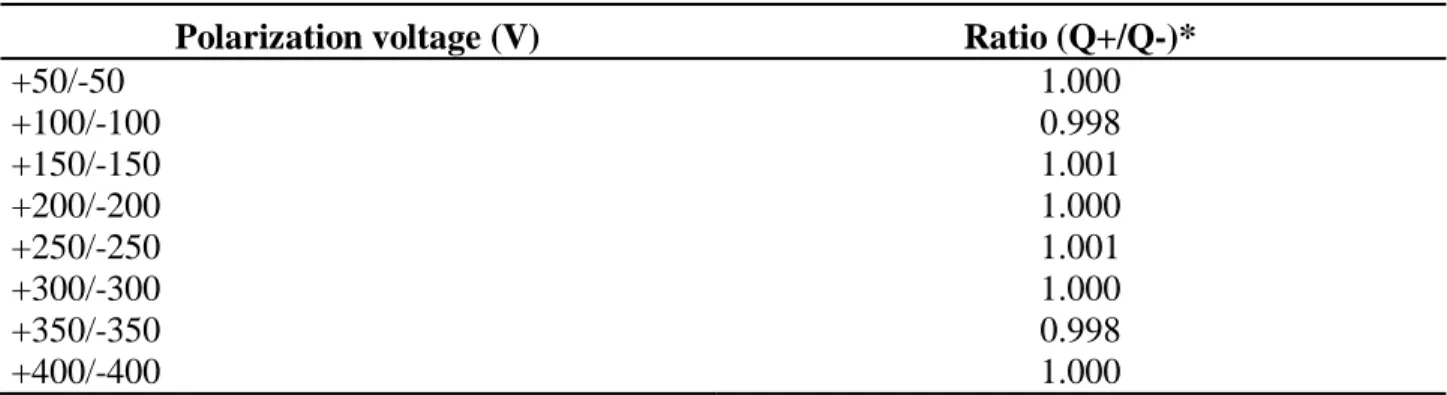
The polarity effect shows how the change in the chamber polarity affects the ionization cham-ber response [13]. According to IEC, the polarity effect results should be within 1.0% [14]. In the saturation region, the effect of the polarity was less than 1.0% for the special ionization chamber, as seen in Table 2, and it was determined by the ratio between the collected charges at both polarities. The operational voltage was chosen to be +300 V for the special ionization chamber.
Table 2: Polarity effects of the special ionization chamber
Polarization voltage (V) Ratio (Q+/Q-)*
+50/-50 1.000 +100/-100 0.998 +150/-150 1.001 +200/-200 1.000 +250/-250 1.001 +300/-300 1.000 +350/-350 0.998 +400/-400 1.000
*Q+ is the collected charge in positive polarity and Q- is the collected charge in negative polarity
3.4. Linearity of the response
The linear relationship between the ionization current and the air kerma rate was determined by irradiating the chamber with the WMV 28 radiation quality (Table 1). The special ionization cham-ber was positioned at the calibration distance, and it was polarized with +300 V. The tube current varied from 2.0 mA to 35.0 mA in order to obtain different values of air kerma rates. For each point, ten measurements were performed and the mean values are presented in Figure 4. The special ionization chamber exhibited a linear response in the range of the tested air kerma rates, and the correlation coefficient was greater than 0.9999.
Figure 4: Linearity of response of the special ionization chamber. The overall uncertainty
was less than 0.05%, not seen in the figure
3.5. Stabilization time
To evaluate the stabilization time of the ionization chamber, the ionization current was meas-ured for +300 V after 15, 30, 45 and 60 min of voltage application. The ionization chamber was irradiated with the 90Sr +90Y control source positioned at 1.0 mm from the chamber entrance win-dow. The results were normalized to the measurement at 60 min [12] and they are shown in Table 3. The ionization current measurements taken 15, 30 and 45 min after application of voltage were less than 2% of the value measured at 60 min, as recommended by the IEC [12].
Table 3: Stabilization time for the special ionization chamber Time after the application of polarizing voltage (min) Ratio (I/I60)*
15 1.0012 ± 0.0002
30 1.0006 ± 0.0003
45 0.9999 ± 0.0001
60 1.0000 ± 0.0001
3.6. Directional dependence
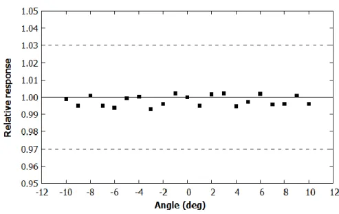
This test was performed placing the special ionization chamber at a goniometer at the reference distance. Both the ionization chamber sensitive volume and the goniometer centers were made co-incident to guarantee the correct angular displacement. The co-incident radiation angle was varied in steps of 1° from 0° to 10° and the angles were changed in clockwise and counterclockwise senses. The counterclockwise was considered as the positive one. Ten measurements were taken for each angle, and the mean values were considered. All results were normalized to the one for 0°. In Figure 5 are presented the results for the angular dependence test. It can be seen that the special ionization chamber presents an angular dependence within ±1.0% for all angular variations between 0° and ±10°, for the WMV 28 radiation quality beams. The limit of ±3.0% is recommended for this kind of detector in mammography energy range [12].
Figure 5: Directional response of the special ionization chamber. The dashed lines
3.7. Energetic dependence
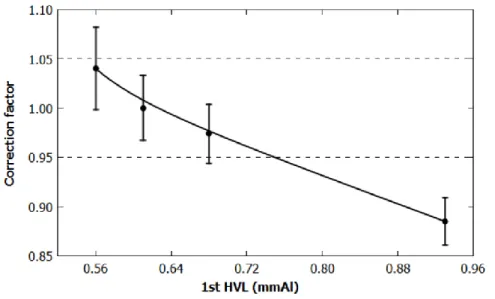
The response of the ionization chamber in function of the half value layer was studied using the radiation qualities listed in Table 1. The calibration coefficients and the correction factors obtained are presented in Table 4. In Figure 6 and in Figure 7, the response of the ionization chamber is pre-sented in terms of the correction factors, normalized to the qualities WMV 28 and WMH 28.
Table 4: Calibration coefficients and correction factors for the special ionization chamber at WMV and WMH radiation qualities
Radiation quality HVL (mmAl) Calibration coefficient (×106 Gy/C) Correction factor Direct beams WMV 25 0.36 3.819 ± 0.037 1.001 ± 0.014 WMV 28 0.37 3.817 ± 0.037 1.000 ± 0.014 WMV 30 0.38 3.796 ± 0.037 0.994 ± 0.014 WMV 35 0.41 3.706 ± 0.036 0.971 ± 0.013 Attenuated beams WMH 25 0.56 3.738 ± 0.123 1.040 ± 0.042 WMH 28 0.61 3.596 ± 0.084 1.000 ± 0.033 WMH 30 0.68 3.503 ± 0.071 0.974 ± 0.030 WMH 35 0.93 3.182 ± 0.045 0.885 ± 0.024
Figure 7: The special ionization chamber energy response for WMH attenuated beams
It can be seen that the special ionization chamber has a flat response with a variation within the recommended limit of ±5.0% of IEC for this kind of detector [12] for the WMV mammography energy range. For the WMH 35 mammography radiation quality, the ionization chamber presented energy dependence higher than 5.0%; that is no problem, because the practical half-value layers for mammography are within 0.25 and 0.65 mmAl [3]. At this HVL interval the ionization chamber behaves according to the IEC international standard.
4. CONCLUSION
The special ionization chamber was tested in standard mammography radiation fields estab-lished at LCI/IPEN. This ionization chamber showed adequate response in all performance tests using the reference mammography WMV 28 quality and the 90Sr+90Y control source. Through the saturation curve data it was possible to verify the polarity effect that was negligible for this ioniza-tion chamber in the polarizaioniza-tion voltages utilized in this work. It was also noted that the recombina-tion losses are within internarecombina-tional recommendarecombina-tions too.
This chamber presents a linear response with the variation of air kerma rate in a wide range, and at least 15 min are necessary to have response stabilization under continuous irradiation. The
direction of the radiation incidence varying from ±10° did not influence the response of the chamber more than 3%. The mammography homemade ionization chamber presented also an adequate energy response over the entire range of direct and attenuated mammography beams, except for the WMH 35 mammography radiation quality, but it does not interfere in its use in clinical mammography dosimetry. Therefore, it can be concluded that the special ionization chamber can be used in the mammography radiation qualities established at LCI.
ACKNOWLEDGMENT
The authors are thankful to the Brazilian agencies CNPq (Project 301335/2016-8), FAPESP (Project 2008/57863-2) and MCTIC (Project INCT for Radiation Metrology in Medicine, 573659/2008-7), for partial financial support.
REFERENCES
[1] ICRP - International Commission on Radiological Protection. Managing patient dose in digi-tal radiology. ICRP 93, Ottawa: ICRP, 2004.
[2] MEGHZIFENE, A.; DANCE, D. R.; McLEAN, D.; KRAMER, H.-M. Dosimetry in diagnostic radiology. Eur. J. Radiol., v. 76, n.1, p. 11-14, 2010.
[3] IAEA - International Atomic Energy Agency. Dosimetry in diagnostic radiology: An interna-tional code of practice. IAEA TRS 457, Vienna: IAEA, 2007.
[4] YOSHIZUMI M. T.; CALDAS, L. V. E. Design and assembly of a simple monitor ionization chamber, In: THIRD EUROPEAN INTERNATIONAL RADIATION PROTECTION ASSOCIATION CONGRESS, 2010, Helsinki. Proceedings. p. 14-16.
[5] PERINI, A. P.; NEVES, L. P.; VIVOLO, V.; XAVIER, M.; KHOURY, H. J.; CALDAS, L. V. E. Characterization of a CT ionization chamber for radiation field mapping. Appl. Radiat. Isot., v. 70, n. 7, p. 1300-1303, 2012.
[6] SILVA, J. O.; CALDAS, L. V. E. A double faced ionization chamber for quality control in di-agnostic radiology beams. Appl. Radiat. Isot., v. 70, p. 1424-1428, 2012.
[7] NONATO, F. B. C.; SAKURABA, R. K.; CRUZ, J. C.; CALDAS, L. V. E. Characterization tests of a new parallel plate ionization chamber for use in electron beams. Rad. Phys. Chem., v. 104, p. 244-247, 2014.
[8] IAEA - International Atomic Energy Agency. Quality assurance programme for digital mammography. IAEA HHS 17, Vienna: IAEA, 2011.
[9] SHAFIRI, B.; ZEINALI, H. Z.; SOLTANI, J.; NEGARESTANI, A.; SHAHVAR, A. Investiga-tion and performance tests of a new parallel plate ionizaInvestiga-tion chamber with double sensitive volume for measuring diagnostic X-rays. Nucl. Inst. Meth. A, v. 770, p. 177-181, 2015.
[10] PTB - Physikalisch-Technische Bundesanstalt. Radiation qualities used for studies in radiation protection. Available at:
<www.ptb.de/cms/fileadmin/internet/fachabteilungen/abteilung_6/6.2/6.25/ptb_rad_qual_2015 _01_07.pdf>. Last accessed: 31 Jan. 2018.
[11] IAEA - International Atomic Energy Agency. Absorbed dose determination in external beam radiotherapy: An international code of practice for dosimetry based on standards of absorbed dose to water. IAEA TRS 398, Vienna: IAEA, 2000.
[12] IEC - International Electrotechnical Commission. Medical electrical equipment—dosimeters with ionization chambers and/or semi-conductor detectors as used in X-ray diagnostic imaging. IEC 61674, Geneva: IEC, 1997.
[13] ZHU, T. C. Small Field: dosimetry in electron disequilibrium region. J. of Phys. Conf. Ser. v. 250, p. 1-10, 2010.
[14] IEC - International Electrotechnical Commission. Medical electrical equipment—Dosimeters with ionization chambers as used in radiotherapy. IEC 60731, Geneva: IEC, 2011.