Braz. J. of Develop.,Curitiba, v. 6, n. 9, p. 67576-67590 sep. 2020. ISSN 2525-8761
Dificuldades e limitadores da otimização da produção de placas de circuito
impresso
Dificulties and constraints for optimization on printed circut board
manufacturing
DOI:10.34117/bjdv6n9-261
Recebimento dos originais: 01/09/2020 Aceitação para publicação: 11/09/2020
Neemias de Macedo Ferreira
Master of Enginneering, Centro Paula Souza.
Micropress Ltda. - R. Angaturama, 51 - Sacoma, São Paulo - SP, 04164-010 E-mail: [email protected]
Maria Lúcia Pereira da Silva Ph. D. in Physical Chemistry, USP
Faculdade de Tecnologia de São Paulo, CPS e Escola Politécnica, USP Av. Prof. Luciano Gualberto, 158 - Butantã, São Paulo - SP, 05508-010
E-mail: [email protected] RESUMO
O setor eletroeletrônico caracteriza-se pela rápida taxa de mudança, grande competitividade e necessidade de produção rápida. Este também é o caso da área de produção de placas de circuito impresso. Assim, o objetivo deste trabalho foi mapear as dificuldades e limitações em relação à demanda, processos produtivos e características da placa de circuito impresso que impactam no planejamento da linha de produção. A metodologia utilizada foi o estudo de caso. Para tanto, mapeou-se a situação da linha de produção bem como as características da placa de circuito impresso que são relevantes no planejamento. Os dados obtidos indicam para o balanceamento de linha como uma solução para otimização do planejamento de produção. Portanto, na etapa final um processo modificado, e informalmente denominado Processo Micropress pelos colaboradores, mostrou-se eficiente para otimização de recursos materiais, incluindo tempo, e facilitador a atuação humana.
Palavras-chave: Balanceamento de Linha, Placa de Circuito Impresso, Planejamento de produção, Otimização de processo.
ABSTRACT
Nowadays all electronic sector, including Printed Circuit Board (PCB) industry, presents as main characteristics high rate of change, exceeding competitiveness and the need for quick manufacturing. This works aims mapping difficulties and constraints regarding demand issues, productive processes and particular PCB characteristics that directly impact the production line. The Methodology used case study. The two main steps were mapping of line production´s situation as well as relevant printed circuit board features for the planning. Data obtained indicates line balancing as a solution for line producing optimization. The final step was set the production in a new model, informally described as Micropress process for the employees, which proved to be efficient for optimization of material resources, including time, and an enabler for human actuation.
Braz. J. of Develop.,Curitiba, v. 6, n. 9, p. 67576-67590 sep. 2020. ISSN 2525-8761
Keywords: Line Balancing, Printed Circuit Board, Production planning, Process Optimization.
1 INTRODUCTION
From the last decades of XX century up to now the knowledge revolution was in unprecedent way not only on intensity but also in change rate. This scenery was assigned as new age and nominated as infoera for ones (ZUFFO, 2005)(CARVALHO, KANISKI, 2000) or anthropocene by others (CRUTZEN & STOERMER, 2000) (ARTAXO, 2014)(LEWIS & MASLIN, 2015). Infoera points towards changes in the electronic sector and their consequences on practically any way for the production of goods and services; these outcomes also promote huge changes on job relationships. On the other hand, the anthropocene concept deals with the idea of human and their production and consumption systems as responsible for a harsh global environmental impact, although it also claims for the denial to a separation of Nature and Humanity (LATOUR, 2014).
In Brazil, the electronic sector comprises one very neglected although relevant area: the PCB manufacturing. In a way or another, PCBs are present on each and every electronic equipment and are essential for their functioning. Moreover, the complexity of these PCBs escalates with the increase on technological evolution of this equipment. For instance a PCB for cell phone is much more complex that the one presents on a TV remote control.
The PCB market, as well as the entire electronic sector, is globalized. Globalization allows easily obtaining raw material and finished goods all around the globe but also increases competitiveness. As a consequence, efficiency and cost reduction on production systems expand and, as a reflection, prices decrease; thus delivery time and product quality become attributes on client evaluation, thereby, due to severe competition among enterprises, consumer take into consideration other features during the acquisition process. On this context, China is the big player since they are the biggest electronic producers, with roughly 50% of the global market (WECC, 2018), which, considering other PCB suppliers on the region, turns the PCB production Asiatic in its majority.
For long time, the quality of Chinese products was questioned, which implied in competitive advantage for Brazilian enterprises since, in general terms, these companies show products with better quality than the Chinese ones (CARMO et. al., 2014); however, this perception has changed, especially on the electronic sector (ZHU & TOMASI, 2020). Nevertheless, Asiatic companies also have drawbacks due to logistic factors, since the transfer from one mainland to another on a ship is long-term service whereas air service has prohibitive high cost, especially whether high volume should be moved. Hence, in some cases delivery time is still a differential on the Brazilian market, especially with companies that must speed delivery services owing to unexpected requests. In order
Braz. J. of Develop.,Curitiba, v. 6, n. 9, p. 67576-67590 sep. 2020. ISSN 2525-8761
to minimize the delivery time on these unforeseen situations, the possible other way is providing for bigger stocks, but that also means financial resource immobilized, which directly impacts cash flow (Oliveira et al, 2014).
In conclusion, in order to compete with Asiatic companies, product flexibilization and diversification aside from shorter delivery time have been the commonest strategy for obtaining competitive advantages. Thus, the machinery, once adapted to a single product or business, must be fitted in a flexible way. Nonetheless, a low cost flexible manufacturing line capable of attending vast range of products requires carefully planning to assure resource optimization (equipment, workforce, raw material) and low operating costs. Therefore, nowadays one of the most challenge situations to the production managers is how, at same time in a batch, to balance all the production issues with minimum operational costs but also preserving quality and delivery time.
Thus, this work aims the evaluation of hindrances and limitations that occurs in a PCB line using work-in-process approach and then the detection and elimination of waste, as proposed by WOMACK et al (1992).
2 THEORETICAL FUNDAMENTS 2.1 PRODUCT OPTIMIZATION
The scientific management, as implemented by Frederick Taylor, pointed out to look for an optimized way of operating a production line. This task is performed by the planner that should thoroughly define the production method, evaluating it continuously and adding value to the production line (TAYLOR, 1990).
The time study is also part of the scientific management as well. After the definition of the method, the determination of optimum time to be expended in a task is possible. The sum of all times spent in a production line allows the identification of production bottlenecks and the improvement of these troubled processes, reducing operating costs and, in a virtual cycle, balancing the production line. Batalha et al (2008) states that Taylor worried about efficiency enormously, which led him to focus on waste of resources and time; as a consequence, process chronoanalysis emerges. In this case, any production activity, the begin, the end and respective constituents, is evaluated, revised and rebuilt in a way that the total time for execution is minimized. Later, Henry Ford improved and evolved Taylor´s concepts: interchangeability – the use of standard pieces and interchangeable among products - and assembly line - each workstation responsible for one step on product manufacturing up to the end and dispatch.
On the 1960s, studies developed by Japanese during post-war era regarding scientific management appeared. Hence, on the 1970s new bunch of techniques were added to Taylor´s and
Braz. J. of Develop.,Curitiba, v. 6, n. 9, p. 67576-67590 sep. 2020. ISSN 2525-8761
Ford´s methods aiming maximum coordination between production and demand, avoiding waste, delays and excessive stocks, which is linked to materials management, layout, product project, quality management, the organization of work and HR management. The paramount example of such philosophy is Just in Time (JIT) aside from Lean Production, waste elimination and Quality Circles (SILVA et al, 2020). This environment led to continuous flow manufacturing or balanced production, which focus is on quick and effective solution problem. Japanese companies also burst the Taylor principle of operator-planner; thus, detail and standardization of work were made in a democratic and participative way, which drives employers, managers and operators to work together aiming production effectiveness. At this point, company managers were able to envisage alternative market segments that could be target and, as doing so, establish higher variety of products in a more flexible company; thus, this virtuous cycle also comprises the client evaluation concerning delivery time and product quality as a competitive differential.
All in all, therefore, the machinery formerly designed and used for just one business model or product required adjustment. Nonetheless, low cost flexible manufacturing line capable of supplying vast range of products demands carefully planning in order to maximize resources while maintain low operational cost and high quality and delivery time for each batch.
An efficient way of doing so, i.e., to keep an efficient management of resources is the use of line balancing, determining bottlenecks with two approaches: on the “system capacity” and on “type of products”. According to BECKER & SCHOLL (2006), two variables must be considered: cycle time and number of workstations. Cycle time cannot exceed the sum of all time tasks associated to the Workstations, aside from the request of minimum number of Workstations. Since the number of workstations is fixed, the time required to fulfill the whole operation will be the sum of all times expended in each workstation and must be minimized. Subsequent works added more parameters to be considered and, as pointed out by Rajan et al (2018), Dimitriadis “presented a work on assembly line balancing and group working” that results in “shorter physical line length and production space utilization improvement” whereas Amem “presented a work on cost-oriented assembly line balancing” and proposed “that the maximally loaded station rule was to be replaced by the two-station rule”; moreover, the author emphasizes the use of cost-oriented approach in order to “minimizing total cost per production unit”.
Nowadays, PCB manufacturing attends to these criteria since at least three different PCB technologies are produced simultaneously. In this condition, line balancing is constant and can mean an optimization.
Braz. J. of Develop.,Curitiba, v. 6, n. 9, p. 67576-67590 sep. 2020. ISSN 2525-8761 2.2 PRINTED CIRCUIT BOARD MANUFACTURING
Womack et al (1992) defines two types of products that could be obtained on manufacturing lines: make-to-stock and make-to-order. The make-to-stock ones can be considered standard products, i.e., meant to be stored and be sold in future sales, which also means that stored is foreseen according to sales prospect. On the other hand, the make-to-order are produced on the clients request, i.e., due to the specific utilization they have, they should not be stored because either they can be used by just one customer or they will not be used again at all. Subsequent works added ideas for strategic approach on bottleneck determination of make-to-order products (LIZARRALDE et. al., 2020).
PCBs are make-to-order products, which means there will not be stocks on the suppliers´ companies after all each circuit has its specificity and usage forms. Moreover, there are plenty of different products with distinct characteristics to be manufactured at same time, which complicates production planning (FERNANDES-FLORES et al, 2009). Thus, planning the production claims to consider the distinct PCB technologies that can be: Single Sided – there is circuit on only one face of the board, Double Sided – circuits on both side of the board, Multilayer – several circuits in the inner of the board, Flexible – can be single or double face but the substrate is made from flexible material, such as polyimide, and Rigid-Flex, i.e., the simultaneous produce of two rigid boards connected by a flexible circuit.
On a PCB plant floor, the product manufacturing is a combination of chemical, mechanical and photographic processes coupled to computer programming in CAD/CAM workstations. Furthermore, the distinct PCB manufacturing technologies have some processes in common.
3 METHOD
This works was a case study on Micropress Ltd., a PCB company. According to YIN (2005), case study is a research model for work out a specific situation that proportionally corresponds to the reality in which the research context is inserted. Some steps are required, as follows: a) preparing to collect evidence; b) defining case and gathering data; c) analyzing data and conduct of the case; d) conclusion. Preparing case study means planning based on theoretical framework whereas defining such study implies definition of objectives and choice of interesting data and achievement of an optimum level of detailing. Conducting the case study points out the research focus; therefore, all important variables that influences, directly or indirectly, the case must be catalogued and all instruments that will be used should be defined. Some examples are: interview, observation and documentation. Conclusion is the impartial presentation of all collected data and, as consequence, the observed possibilities for improvement and changes can be described.
Braz. J. of Develop.,Curitiba, v. 6, n. 9, p. 67576-67590 sep. 2020. ISSN 2525-8761
This work is based on time measurements and uses the production records of each process for that. The production times of the processes in the case study company are recorded, in a traceable document and at all times, by the operators responsible for the execution of each process. Thus, samples were collected from batches produced considering their general production times and time spent in each process. These collected data make it possible to understand, for a set of batches produced in a given period of time, the more important variables that determine such time periods and, through critical analysis, to verify possible improvements.
Established since 1986, Micropress is a high-tech company, with about 50 employees and 1500m² of built area. Its business plan focuses on prototype production, supporting the development market, as well as the manufacturing of small and medium volume batches. It has a flexible manufacturing line and can produce single sided, double sided and up to 16 layers multilayer PCBs, containing Blind and Buried vias. Its daily production capacity is 8m²/day and this volume is spread on more than 20 models every day. The company is also known by its quick-turn productions, with delivery times of 8 hours, i.e., if customer’s documentation is received up to 9 am, the PCB is manufactured and dispatched at 5 pm on the same day. Other delivery times are offered by adding an extra day to the aforementioned period up to an interval of 4 days. Its punctuality indicator points to 95% of compliance with the delivery time, and the delay, if happens, is only one working day.
Micropress has ISO 9001: 2015 certification and is the only one qualified by INPE (National Institute for Space Research) and also to produce PCBs for the Brazilian Space Programs, according to the requirements of the IPC A-600-J and IPC 6012D Standards, including its Space requirements. The facility includes physical and chemical laboratory for internal control of chemical processes and microsectioning of the produced PCBs. In addition, all products are make-to-order, that is, the PCBs are ordered according to prototypes development and small batches, which means different characteristics on each batch; therefore, there is no possibility of producing PCBs for storage. All production requests go through the production planning process and impact the production line balance.
4 RESULTS AND DISCUSSION
The following steps were carried out settling the critical operations: A) understanding of production process, B) determination of process flow, disclosing and measuring of main factors that influence the production time, C) throughout the critical analysis of the previously obtained results, propose improvement actions and D) implementation of a balanced line. Thus, this sequence is similar to the application of the PDCA (Plan-Do-Check-Act) method to a production process. The
Braz. J. of Develop.,Curitiba, v. 6, n. 9, p. 67576-67590 sep. 2020. ISSN 2525-8761
proposed improvement results from the application of FMEA (failure mode and effect analysis) to the data obtained in the previous step.
A. Understanding of production process
At this step, the company's production line was audited, which means all processes on the manufacturing line were compiled, listed and briefly described. It is worth remembering PCBs manufacturing is a combination of process: chemical, mechanical, photographic, silkscreen processes, in addition to the packaging and engineering inspection steps associated with the programming carried out in CAD/CAM stations. Then, the processes were correlated with the respective PCBs manufacturing lines, single sided, double sided and multilayer, and listed in the order they should be carried out. All this information is shown on Table 1.
Braz. J. of Develop.,Curitiba, v. 6, n. 9, p. 67576-67590 sep. 2020. ISSN 2525-8761
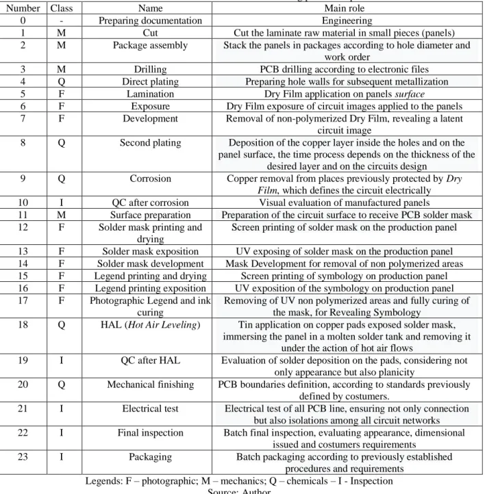
Table 1 – PCB Double Sided manufacturing process steps
Number Class Name Main role
0 - Preparing documentation Engineering
1 M Cut Cut the laminate raw material in small pieces (panels) 2 M Package assembly Stack the panels in packages according to hole diameter and
work order
3 M Drilling PCB drilling according to electronic files 4 Q Direct plating Preparing hole walls for subsequent metallization 5 F Lamination Dry Film application on panels surface
6 F Exposure Dry Film exposure of circuit images applied to the panels 7 F Development Removal of non-polymerized Dry Film, revealing a latent
circuit image
8 Q Second plating Deposition of the copper layer inside the holes and on the panel surface, the time process depends on the thickness of the
desired layer and on the circuits design
9 Q Corrosion Copper removal from places previously protected by Dry Film, which defines the circuit electrically 10 I QC after corrosion Visual evaluation of manufactured panels
11 M Surface preparation Preparation of the circuit surface to receive PCB solder mask 12 F Solder mask printing and
drying
Screen printing of solder mask on the production panel 13 F Solder mask exposition UV exposing of solder mask on the production panel 14 F Solder mask development Mask Development for removal of non polymerized areas 15 F Legend printing and drying Screen printing of symbology on production panel 16 F Legend printing exposition UV exposition of the symbology on production panel 17 F Photographic Legend and ink
curing
Removing of UV non polymerized areas and fully curing of the mask, for Revealing Symbology
18 Q HAL (Hot Air Leveling) Tin application on copper pads exposed solder mask, immersing the panel in a molten solder tank and removing it
under the action of hot air flows
19 I QC after HAL Evaluation of solder deposition on the pads, considering not only appearance but also planicity
20 Q Mechanical finishing PCB boundaries definition, according to standards previously defined by costumers.
21 I Electrical test Electrical test of all PCB line, ensuring not only connection but also isolations among all circuit networks 22 I Final inspection Batch final inspection, evaluating appearance, dimensional
issued and costumers requirements
23 I Packaging Batch packaging according to previously established procedures and requirements
Legends: F – photographic; M – mechanics; Q – chemicals – I - Inspection Source: Author
Whereas Single sided PCBs do not use processes numbers 4 and 2, Double sided ones require all of them and on the described order (Table 1). Multilayers PCBs present inner layers whose production process is almost the same of Single sided ones; therefore, these processes will be repeated as often as the amount of inner layers. Nonetheless, the processes on these PCBs are on both sides; thus, the productive process on Multilayer PCBs can be characterized as external and internal layers. Internal layers manufacturing depends upon process numbers 1, 11, 5, 6, 7, 9, 10 and 11, which order, due to materials requirement, can be slightly altered. At the end of the internal layers process there will be pressing and, after that, the manufacturing is the same as the Double sided PCBs. This complex flow among PCBs technologies poses a challenge for the manufacturing
Braz. J. of Develop.,Curitiba, v. 6, n. 9, p. 67576-67590 sep. 2020. ISSN 2525-8761
management system. Furthermore, the most evident marketshare of the case study company is the differentiated delivery time, making this whole combination of factors critical and any loss of time in balancing the production line or in managing failures can lead to losses not only in costs but also in customer satisfaction in case of delay in product delivery.
Other important aspects to be taken into account are the technological evolution and the miniaturization of the components, which imposes the adaptation of the PCB designs to this reduction in size of the components, as well as the available area for the circuit layout. This results in a reduction of the tracks width and holes diameter and an increase in the number of electrical nets in the circuit. These characteristics have an impact on the time of certain processes, which increases the existing complexity in PCBs production schedule.
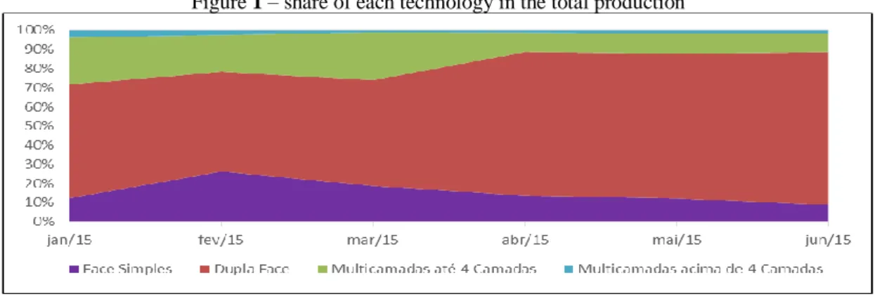
This case study comprises Single and Double sided as well as Multilayers (up to 4 layers) PCBs because this manufacturing corresponds to 95% of all manufactured products, as shown in Figure 1.
Figure 1 – share of each technology in the total production
Source: Author.
B. Determination of process flow
In order to obtain a significant amount of information about the process flow, it was obtained the production records of the batches delivered during a randomly chosen week. The production records present the aforementioned processes (Table 1) and the moment of completion of the batch; furthermore, the start time of any process is considered to be the end of the previous one. Thus, this data allows evaluation of production planning condition, regardless the PCB technology produced at that moment, its quantity and complexity. The evaluated week had a total of 30 batches processed, which corresponds to an average production situation, according to the O&M manager. This production was distributed among the PCBs technology same way as the average, which means having 3 Single-sided batches (10%), 22 Double-sided batches (73%) and 5 Multi-layer, up to 4 layers, batches (17% ).
Braz. J. of Develop.,Curitiba, v. 6, n. 9, p. 67576-67590 sep. 2020. ISSN 2525-8761
It is worth noting that, regardless the quantity of PCBs produced in this process each model produced is defined as a batch. Thus, the volume of the batch is exceedingly important on evaluation of critical factors. The larger the batch, and also depending on the complexity of PCBs characteristics, the longer the processing time, which will directly impact the queue in production management.
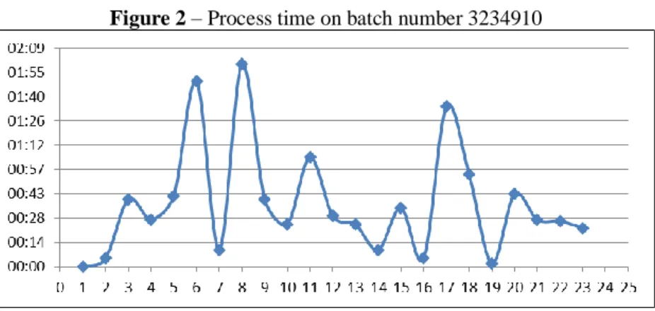
The data records were transferred to an electronic spreadsheet and the obtained graphics allow a visual analysis of the work processes status. Figure 2 shows obtained results for a single batch, which number is 3234910, of the collected sample. This batch corresponds to the production of Double-sided PCBs, which is the largest production volume in this case study. In this figure, the ordinate axis corresponds to the process duration time (hours and minutes) and the abscissa axis consists of the process itself, numbering as the same in Table 1. It is possible to identify some processes that stand out in relation to the entire production process duration. For instance, Dry Film Exposure, Second Metallization, Photographic Legend and ink curing were the processes showing the longest processing time.
Figure 2 – Process time on batch number 3234910
Source: Author
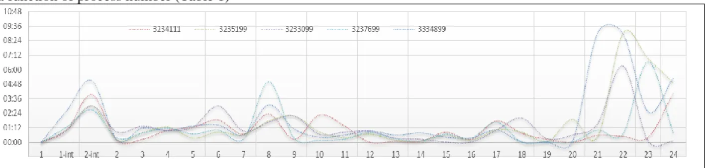
After analyzing the process flow, FMEA was done, in a partnership with the O&M engineer, for determining why those were speed limiting steps. In order to allow comparison and also to determine trends, graphs of the production time for all the batches of Double Sided and Single Sided PCBs within the sample week were overlaid (Figure 3) and, after that, the same for Multiplayer processing (Figure 4).
Braz. J. of Develop.,Curitiba, v. 6, n. 9, p. 67576-67590 sep. 2020. ISSN 2525-8761
Figure 3: Process flow for 25 batches of Single-sided and Doubled-sided PCBs: duration of the production process (hours and minutes) as a function of process number (Table 1)
Source: Author.
Figure 4 – Process flow for 5 batches of Multilayers PCBs: duration of the production process (hours and minutes) as a function of process number (Table 1)
Added processes for innerlayers. Brown Oxide and Pressing,they make part of Multilayer processing Source: Author.
In figures 2-4, it is possible to observe some processes time are higher than 3 hours and 30 minutes, specially processes 3 (drilling), 8 (second plating), 20 (mechanical finishing), 21 (electrical test), 22 (final inspection) and 23 (packaging), for Double-sided and Single-sided PCBs. For Multilayers, the time peaks occur in processes 2 - int (pressing), 6 (dry film exposure), 8 (second plating), 20 (mechanical finishing), 21 (electrical testing), 22 (final inspection) and 23 (Packing). The drilling process depends on 3 factors: Number of panels, smaller hole diameters and number of holes in the panel. These factors have a strong impact on the production flow and it is not uncommon for only one panel to take 1 hour for drilling.
Since it is an electrolytic copper deposition, the Second Plating in an ideal process would have fixed running time. However, depending on the circuit layout - small lines (less than 6 mil) and holes with small diameters (less than 0.3 mm) - it requires reduction in the applied current density. Otherwise, metallization in excess could occur and on the thin tracks would cause short-circuits during corrosion process whereas on the small diameter holes could favor deposition at the edge of the holes at the expenses of the wall deposition.
V-Scoring is a process for grinding the panel surface, thus two discs simultaneously rough through the entire length of the production panel, in both, X and Y, directions. For each produced
Braz. J. of Develop.,Curitiba, v. 6, n. 9, p. 67576-67590 sep. 2020. ISSN 2525-8761
model, the number of v-cuts is variable, as it is dependent on customer specifications, the more creases on the production panel, the longer the process time.
Like the v-scoring, routing is totally dependent on customer specifications. The main factors that must be considered to define the process time of each batch during the completion of the production are: number of non-metalized holes, milling cutter diameter, as well as the linear milling length.
The electrical test time for each batch is difficult to estimate as it depends on the number of electrical connections in the tested model. Furthermore, on the PCBs where there is not balance among test points on solder and component sides, overload on one side of the point-to-point test machine may occur, leading to an increase in electrical test time. In addition, this process is an accurate check upon the circuit connections designed by the customer, which means it is fundamental for the quality of the product. Thus, defects that were not found by intermediate inspections, such as short or open circuits, can be detected. The location of these defects for later removal (in the case of short circuits) can be time consuming and impact the electrical test time.
On Multilayer PCBs, time for pressing process depends on the number of panels to be manufactured, varying from 2 to 4 hours. As it is a long process, it naturally impacts the total process time. Also in Multilayer PCBs, Dry Film exposure is a speed limiting process due to the needs of such technology, that requires be processed twice, once for the innerlayers and other for outerlayer images. Therefore, the time of this process comprises the time spent to expose the internal and external layers. However, the process for registering the images of internal layers is different from the registration of the external ones.
After surveying the possible reasons for the increase in processing time, a qualitative analysis were carried out to evaluate if the results presented in figures 2 to 4 could be explained just for differences in the PCBs technologies in a given batch. It was observed that the variability between batches is much greater than the technical reasons listed. Therefore, it was observed a delay due to the need of using the same machine for different production times in batches being processed in parallel.
C. Critical analysis and proposal for improvement actions
Determination of process flows and FMEA application reveal a problem of queues managing before the speed limiting processes that were pointed out in figures 2-4, which also positively impacts the management of the production line. Therefore, there is a similarity between the PCBs production process and logistical processes, for instance, such as container management in warehouses or ports; thus, a similar strategy can be useful in this case. In fact, the company under
Braz. J. of Develop.,Curitiba, v. 6, n. 9, p. 67576-67590 sep. 2020. ISSN 2525-8761
study previously used a common logistics program (Preactor®) for production management. The concept of this program is to exhaust process capacity, which can be an inconvenience, as it does not focus on optimizing production by managing the variables, which can be achieved by balancing the line.
Therefore, the objective is balancing the production line, in order to equalize the variables of each batch, the technology processed, the available resources, as well as the deadlines established with each customer. If doing so, forecast the end of production at the beginning of the process, which allows observation of probable setbacks and taking actions to avoid them. Thus, line balancing is suited to deal with this complex situation, as proposed in lean manufacturing references (WOMACK, et al 1992), as it is a possibility for improving the management of the production line. This comes from the possibility of allocating machinery and human resources in a correct way, which allows a more continuous flow of batches.
D. Implementation of a balanced line
Implementation of a balanced line was carried out in two main steps: simulation and test. First, each process and machine time were measured; then, a spreadsheet was created to include all the meaningful data, not only time but also important process characteristics. After that, a simulation of continuous batches was performed using the spreadsheet and the results for 15 simultaneous batches are shown in Figure 5. It is possible to observe the lack of delay times and a smooth production line. Moreover, the longest running process is the second plating; thus the balancing was designed to assure that this step would be continuously feed, i.e., without stops.
Braz. J. of Develop.,Curitiba, v. 6, n. 9, p. 67576-67590 sep. 2020. ISSN 2525-8761
On a second step the production line was tested using the balanced spreadsheet as a guideline and Figure 6 shows an actual production data. Although some intercurrence still arises, a much less speed limited production line appears.
Figure 6– Process flow for 28 PCBs batches: time for the process initialization as a function of process number (Table 1)
5 CONCLUSIONS
This paper mapped difficulties and limitations in relation to demand, production processes and characteristics of PCBs that impact planning within a fast production scenario. The scenario analysis led to the proposal of line balancing to optimize production, which is not an easy option because each process has its own characteristics, therefore they are not identical. Each process, even if used for the same function, has different technical and production capacities, requires different industrial utilities flows (cooling water or compressed air, for instance) and depends on dimensions and product characteristics suitable for processing. These restrictions must be taken into account during the line balancing process. Thus, the greatest advantage of this approach was, in a second step, with this line balancing system applied, minimizing the production time (Takt time), aiming at increasing punctuality in supply contracts. It is important to emphasize that, as far as the author could determine, this approach has not yet been tested in this productive area.
REFERÊNCIAS
ARTAXO, P. Uma nova era geológica em nosso planeta: o Antropoceno? REVISTA USP, São Paulo, n. 103, p. 13-24, 2014
Crutzen, PJ, Stoermer, EF. The ‘Anthropocene’. IGBP Newsletter, vol. 41, p. 17–18, 2000 BATALHA, O.M.; Introdução à Engenharia de Produção, São Paulo, Elsevier, 2008
Braz. J. of Develop.,Curitiba, v. 6, n. 9, p. 67576-67590 sep. 2020. ISSN 2525-8761
BECKER C., SCHOLL, A. A survey on problems and methods in generalized assembly line balancing, European Journal of Operations Research, v.168, 3ed, p.694-715, Fevereiro de 2006. CARMO, A.S.S., BITTENCOURT, M.V.L., RAIHER, A.P. A competitividade das exportações do Brasil e da China para o Mercosul: evidências para o período 1995-2009, Belo Horizonte, Revista Nova Economia, vol.24 no.3 Set./Dez. 2014
CARVALHO, I. C. L.; KANISKI, A. L. A sociedade do conhecimento e o acesso à informação: para que e para quem?. Ciência da Informação, vol. 29, no. 3, p. 33-39, 2000, https://doi.org/10.1590/S0100-19652000000300004
LATOUR, B. Para distinguir amigos e inimigos no tempo do Antropoceno, Revista de Antropologia - USP, São Paulo, v. 57 nº 1, 2014
LIZARRALDE AIASTUI, A.; APAOLAZA PEREZ DE EULATE, U.; MEDIAVILLA GUISASOLA, M. A strategic approach for bottleneck identification in make-to-order environments: A drum-buffer-rope action research based case study. Journal of Industrial Engineering and Management, vol. 13, no. 1, p. 18-37, 2020. http://dx.doi.org/10.3926/jiem.2868. LEWIS, S., MASLIN, M. Defining the Anthropocene. Nature, vol. 519, p. 171–180, 2015. https://doi.org/10.1038/nature14258
OLIVEIRA, H. M. R., REZENDE, L. M. M., KOVALESKI, J.L. Aplicabilidade da filosofia enxuta em indústrias de processo contínuo , Ponta Grossa, IV CONGRESSO BRASILEIRO DE ENGENHARIA DE PRODUÇÃO, 2014
Rajan, A. j., Ramanamurthy, E.V.V, Nath, R., Kumar, P. Productivity enhancement by component-oriented line balancing method, Int. J. Industrial and Systems Engineering, Vol. 29, No. 1, 2018
SILVA, T.; OLIVEIRA, C. C.; ROCHA, R. P. Aplicação do mapeamento do fluxo de valor para identificação e redução de desperdícios na linha de montagem de circuitos eletrônicos, Braz. J. of Develop., v. 6, n. 2, p. 8188 – 8204, 2020, DOI:10.34117/bjdv6n2-212
TAYLOR, F. Princípios de Administração Cientifica. São Paulo, Atlas, 1990.
WOMACK, J.P., JONES, D.T.; ROOS, D. A máquina que mudou o mundo, Campus, Rio de Janeiro, 1992.
WECC Global PCB Production Report For 2018, 2019
YIN, R. Estudo de Caso. Planejamento e Métodos. Porto Alegre: Bookman, 2005
Zhu. M., Tomasi, C. Firms' imports and quality upgrading: Evidence from Chinese firms, The World Economy, vol. 0, p. 1-27, 2020 https://doi.org/10.1111/twec.12934
ZUFFO, J. A. A infoera transformando as relações sociais. Comunicação & Educação, 10, 61-70, 2005