Mechanical characterization
of traditional connections in
half-timbered walls:
experimental results and
retrofitting solutions
DECLARATION
Name: Aikaterini Maria Koukouviki
Email: [email protected]
Title of the Msc Dissertation:
Mechanical characterization of traditional connections in half-timbered walls: experimental results and retrofitting solutions
Supervisor(s): Graça Vasconcelos, Jorge Branco
Year: July 2013
I hereby declare that all information in this document has been obtained and presented in accordance with academic rules and ethical conduct. I also declare that, as required by these rules and conduct, I have fully cited and referenced all material and results that are not original to this work.
I hereby declare that the MSc Consortium responsible for the Advanced Masters in Structural Analysis of Monuments and Historical Constructions is allowed to store and make available electronically the present MSc Dissertation.
University: University of Minho
Date: 24 July 2013
Signature:
To that power that dwells within each one of us… A strength that has no limits or boundaries!
ACKNOWLEDGEMENTS
First of all, I would like to express my gratitude to the European Commission for the scholarship that I was granted. Without this financial help, it would have been impossible for me to attend this Master’s Programme.
My appreciation and special thanks go to my supervisor Professors; Graça Vasconcelos and Jorge Branco, who were always willing to help me and did not stress me at all, throughout the entire time that I was preparing my Thesis, while they provided useful information whenever asked.
At this point, I need to say, that I have more than just appreciated the constant and valuable assistance and guidance that came from Elisa Poletti at all times. She has been too patient with me and I am not using “too” by accident.
While spending sleepless days and nights with Elisa Poletti, at the laboratory performing tests, the help and advice that we received, by the staff: Marco Jorge, António Matos and Alfredo Carlos Lemos was precious. Their kindness will not be forgotten by any of us.
Of course to every person associated with the SAHC Programme, from the teachers that opened new horizons to our knowledge, to Mrs. Ana Fonseca who had to manage all our trouble from time to time, I should say a cordial thank you.
I could not fail to mention both my Professors from the Aristotle University of Thessaloniki, where I completed my previous studies, that apart from knowledge during my studying years, they provided me with the necessary recommendation letters: Professors Dimitrios Aravantinos and Kosmas Stilianidis.
Additionally, I am grateful to Professor Aikaterini Tsikaloudaki who was kind enough to help me with additional information from a relevant previous dissertation that she had supervised.
I would like to thank my colleagues for all the support (moral and scientific), as we all realize how difficult it is to live away from your country. Even though the experience is unique and for many, a once-in-a-lifetime opportunity, it can still become very stressful.
For the same reason I would like to send my warm hugs to all of my family members and my friends in Greece, that were there to lift my spirit!
Last but not least, I am more than obliged to my personal, digital hero, Vítor Costa; the computer technician at the University of Minho, that helped prevent total failure of my laptop several times. Needless to say, that although difficult and highly demanding; SAHC Programme does not cease to fulfill its purpose, as with the completion of my Thesis, I fill more confident academically.
ABSTRACT
Connections are an important part of timber frame structures, as is the case of half-timbered walls and play a major role in their overall behaviour. Therefore, focusing on the connections’ behaviour is essential when addressing the study of seismic response of traditional timber structures.
Half-timbered walls are well known as one of the most efficient seismic resistant structures in the world. The origin of half-timbered structures probably goes back to the Roman Empire and examples can be found in Europe, Asia and the American continent. In Portugal, these buildings, called Pombalino buildings, consist of outer masonry walls and an internal timber cage filled with rubble or brick masonry. Half-timbered walls act as shear walls in these structures and it is essential to study their response to horizontal loads both in their original state and after retrofitting, since a great effort has been made in the last years from a rehabilitation point of view.
In half-timbered walls, and timber frame walls in general, seismic damage is concentrated in the connections. Therefore, the main points of intervention are usually the traditional timber joints. In this study, an experimental campaign on overlapped connections has been carried out studying the response to compressive and horizontal loads and evaluating adequate retrofitting solutions.
In order to better characterize the response of traditional overlapped connections, cyclic in plane tests have been performed in order to obtain information on their seismic behaviour, taking into account their hysteretic behaviour and their dissipative capacity. Moreover, pull-out tests have been performed on the same type of connection in order to better characterize the rocking behaviour observed in traditional half-timbered walls, resulting in important uplift displacements of the bottom overlapped connections.
In this work, results on both these types of tests on traditional timber connections are presented, concerning their unreinforced and their retrofitted states, and recommendations are provided on the retrofitting solutions.
RESUMO
As ligações constituem uma parte importante de estruturas de madeira tal como no caso de paredes tradicionais de madeira e têm um papel fulcral no comportamento mecânico. Assim, o foco colocado no comportamento das ligações é essencial quando se quer estudar o comportamento sísmico de estruturas tradicionais de madeira.
As paredes de frontal são bem conhecidas como sendo um dos elementos construtivos mais eficientes em termos de resistência sísmica. A origem das paredes tradicionais de madeira remontam ao tempo do império Romano e vários exemplos podem ser encontrados na Europa, Asia e no continente americano. Em Portugal, o sistema construtivo com as paredes de frontal são designados de edifícios Pombalinos e apresentam as paredes exteriores em alvenaria de pedra e a estrutura interna constituída por gaiolas que resultam de uma associação de paredes de frontal preenchidas com alvenaria de pedra irregular ou alvenaria de tijolo. As paredes de frontal funcionam como paredes de contraventamento, sendo essencial o estudo do seu comportamento a ações horizontais, com e sem reforço dado que um grande esforço necessário na reabilitação destas paredes.
Em paredes de frontal e paredes de madeira tradicionais, o dano sísmico é concentrado maioritariamente nas ligações. Deste modo, os pontos de intervenção são usualmente as ligações de madeira. Neste trabalho, foi levada a cabo uma campanha experimental em ligações designadas de “ligações meia-madeira” para caracterização do comportamento mecânico a esforços de tração e ações laterais cíclicas e para a avaliação de diferentes técnicas de reforço. Para o efeito, ensaios cíclicos no plano foram feitos para avaliar o comportamento sísmico com base nos diagramas histeréticos força-deslocamento e capacidade de dissipação de energia. Adicionalmente foram feitos ensaios de tração cíclicos no mesmo tipo de ligações com o objetivo de caracterização o seu comportamento em tração, dado que as ligações meia-madeira da base da parede de frontal estão sujeitos a este tipo de ação devido ao comportamento tipo “rocking” das paredes de frontal sujeitas a ações laterais. Neste trabalho, os resultados de ambos os tipos de ensaios são apresentados em provetes sem e com reforço e recomendações são fornecidas acerca das soluções de reforço.
ΠΕΡΙΛΗΨΗ
Χαρακτηρισμός των παραδοσιακών συνδέσμων στις ξυλόπηκτες τοιχοποιίες: Πειραματικά αποτελέσματα και λύσεις ενίσχυσης Οι σύνδεσμοι αποτελούν σημαντικό τμήμα στις τοιχοποιίες με ξύλινο σκελετό, όπως οι ξυλόπηκτες, και έχουν μείζοντα ρόλο στην συνολική τους συμπεριφορά. Ως εκ τούτου, η έμφαση στη συμπεριφορά των συνδέσεων είναι απαραίτητη για την μελέτη της σεισμικής απόκρισης των παραδοσιακών ξύλινων κατασκευών. Οι ξυλόπηκτες τοιχοποιίες, ως γνωστόν είναι από τις πιο αποτελεσματικές, σεισμικά ανθεκτικές δομές στον κόσμο. Η προέλευση τους, πιθανώς πηγαίνει πίσω στην Ρωμαϊκή Αυτοκρατορία και παραδείγματα μπορούν να βρεθούν στην Ευρώπη, την Ασία και την Αμερικανική ήπειρο. Στην Πορτογαλία, τα κτίρια που φέρουν αυτήν την τεχνοτροπία, ονομάζονται “Pombalino” κι αποτελούνται απο την εξωτερική τοιχοποιία λιθοδομής κι έναν εσωτερικό ξύλινο σκελετό – «κλουβί», του οποίου τα κενά συμπληρώνονται με λίθους ακανόνιστου σχήματος και κονίαμα ή οπτοπλινθοδομή. Στην περίπτωση αυτή, οι ξυλόπηκτες τοιχοποιίες συμπεριφέρονται ως τοιχεία, επομένως είναι απαραίτητη η μελέτη της απόκρισής τους σε οριζόντια φορτία, τόσο στην αρχική τους κατάσταση αλλά και αφότου ενισχυθούν, δεδομένου ότι τα τελευταία χρόνια έχει γίνει μια μεγάλη προσπάθεια από πλευράς αποκατάστασης-αναμόρφωσης των εν λόγω κατασκευών. Στις ξυλόπηκτες και στις τοιχοποιίες με ξύλινο σκελετό, η σεισμική βλάβη σε γενικές γραμμές, συγκεντρώνεται στις συνδέσεις. Επομένως, τα σημεία όπου επικεντρώνονται οι επεμβάσεις είναι συνήθως ο παραδοσιακοί, ξύλινοι σύνδεσμοι. Σε αυτή τη διπλωματική εργασία, έχει διεξαχθεί μια πειραματική εκστρατεία με σκοπό τη μελέτη της απόκρισης των επικαλυπτόμενων ξύλινων συνδέσεων κατά την ταυτόχρονη υποβολή τους σε θλιπτικά και οριζόντια φορτία και την αξιολόγηση κατάλληλων λύσεων ενίσχυσής τους. Με σκοπό τον καλύτερο χαρακτηρισμό της απόκρισης στις προαναφερθείσες συνδέσεις, πραγματοποιήθηκαν πειράματα επαναλαμβανόμενης οριζόντιας μετατόπισης εντός επιπέδου με διαφορετικά επίπεδα αξονικής φόρτισης, ώστε να ληφθούν πληροφορίες σχετικά με την σεισμική τους συμπεριφορά, μέσω των βρόχων υστέρησης και της ικανότητας διάχυσης ενέργειας. Παράλληλα, πραγματοποιήθηκαν πειράματα επαναλαμβανόμενης κατακόρυφης μετατόπισης εντός επιπέδου στον ίδιο τύπο συνδέσεων, ώστε να χαρακτηριστεί η παρατηρηθείσα συμπεριφορά «λικνισμού» κατά τη διάρκεια πειραμάτων σε ξυλόπηκτες τοιχοποιίες, που είχε ως αποτέλεσμα σημαντικές μετατοπίσεις ανύψωσης στις επικαλυπτόμενες συνδέσεις της βάσης. Στη δεδομένη εργασία διπλωματικής διατριβής, παρουσιάζονται τα αποτελέσματα για τους δυο προηγούμενους τύπους πειραμάτων στις παραδοσιακές, ξύλινες συνδέσεις, πριν και μετά την ενίσχυσή τους και παρέχονται συστάσεις για λύσεις ενίσχυσής τους.TABLE OF CONTENTS
Chapter 1: Introduction ... 1
1.1 General ... 3
1.2 Objectives and methodology ... 3
1.3 Outline of the Thesis ... 4
Chapter 2: State of the art for half-timbered walls and their connections ... 7
2.1 Historical overview of the half-timbered wall structure ... 9
2.2 Architectural description of a typical half-timbered building in Greece ... 11
2.2.1 Foundation ... 11 2.2.2 Ground floor ... 12 2.2.3 Upper storeys ... 12 2.2.3.1 Half-timbered structure ... 12 2.2.3.2 Inner walls ... 13 2.2.3.3 Jetty ... 14 2.2.4 Floor ... 14 2.2.5 Roof ... 15
2.2.6 Functions and distribution of spaces ... 16
2.3 Description of the connection typologies in half-timbered frames ... 17
2.4 Existing studies on half-timbered walls ... 19
2.5 Existing studies on on half-timbered walls ... 21
Chapter 3: Pull-out and in plane cyclic tests on unreinforced timber connections ... 25
3.1 Introduction ... 27
3.2 Description of specimens ... 27
3.3 Determination of density and moisture content of the wood ... 28
3.4 Determination of superficial moisture content of the wood ... 29
3.5.1 Test setup ... 31
3.5.2 Instrumentation ... 31
3.5.3 Test procedure ... 32
3.5.4 Analysis of results ... 33
3.5.5 Estimation of the load-carrying capacity for the nail ... 40
3.6 In plane cyclic tests ... 44
3.6.1 Test setup ... 44
3.6.2 Instrumentation ... 46
3.6.3 Test procedure ... 47
3.6.4 Results analysis ... 48
Chapter 4: Retrofitting solutions ... 61
4.1 Introduction ... 63
4.2 Available strengthening techniques for the connections ... 63
4.2.1 Nails and screws ... 64
4.2.2 Prosthesis and interlocking ... 64
4.2.3 Bolts ... 64
4.2.4 Steel plates ... 65
4.2.5 Steel flat bars or rods ... 65
4.2.6 Steel embedded connectors in specific connection locations ... 65
4.2.7 Use of innovative techniques - FRP materials (rods and sheets) ... 65
4.3 Description of the applied retrofitting techniques ... 66
4.3.1 Specimens used for pull-out tests... 66
4.3.1.1 Fixing point ... 67
4.3.1.2 Screws ... 69
4.3.1.3 “T” GFRP ... 71
4.3.1.4 Steel plates ... 72
4.3.1.5 NSM with steel rods ... 73
4.3.2 Specimens used for in-plane cyclic tests ... 76
4.3.2.2 GFRP sheets and CFRP strips wrapped ... 79
Chapter 5: Experimental results after retrofitting ... 85
5.1 Introduction ... 87
5.2 Pull-out tests ... 87
5.2.1 “T” GFRP ... 88
5.2.2 Steel Plates ... 90
5.2.3 Screws ... 91
5.2.4 NSM with Steel rods ... 93
5.2.5 Comparison of all retrofitting techniques ... 95
5.3 In-plane cyclic tests ... 98
5.3.1 “T” GFRP ... 98
5.3.1.1 Damaged specimens ... 98
5.3.1.2 Specimens with prosthesis ... 101
5.3.2 Steel Plates ... 107
5.3.3 NSM with Steel rods ... 112
5.3.4 GFRP sheets and CFRP strips wrapped ... 117
5.4 Pull-out tests of GFRP sheets and CFRP strips wrapped ... 121
Chapter 6: Conclusions ... 127
References ... 133
APPENDIX A ... 137
LIST OF FIGURES
Figure 2.1 – a) Horizontally, embedded, wooden elements within the wall, b) Wall made of vertical, wooden, supporting elements that were filled with wattled reeds or nailed laths and covered with
plaster (ksiloplekti tichopiia), c) Half-timbered wall (ksilopikti tichopiia) [6]. ... 9
Figure 2.2 – Local names to describe the studied structure [7],[8],[9]. ... 10
Figure 2.3 – a) Himis in Turkey, b) Ksilopikti tichopiia in Athens, Greece, c) Dhajji-dewari in Kashmir, India, d) Bindingverk in Sweden [9],[10],[7],[8]. ... 11
Figure 2.4 – Structural detail of the stone masonry wall and the foundation [11]. ... 12
Figure 2.5 – Structural detail of the half-timbered wall [11]. ... 13
Figure 2.6 – Structural detail of the inner bagdadi wall [11]. ... 13
Figure 2.7 – Structural detail of the jetty [11]. ... 14
Figure 2.8 – Structural detail of the wooden floor [11]. ... 15
Figure 2.9 – Axonometric configuration of the wooden frame structure of the roof [11]. ... 15
Figure 2.10 – Axonometric configuration of the load bearing structure of the building [11]. ... 16
Figure 2.11 – Axonometric configuration and structural details of the “Pombalina” structure [3]. ... 17
Figure 2.12 – Configuration and structural details of the connections in the “Pombalina” structure [4], [14] ... 18
Figure 2.13 – Configuration and structural details of dovetail connections in a “Pombalina” structure [16]. ... 19
Figure 2.14 – a) Removed wall from “Pombalino” building and tested for strength and stiffness in the Portuguese National Lab by Coias e Silva, b) F-d graph of one from the three walls that were tested, which shows that structural integrity was not lost [7]. ... 20
Figure 2.15 – a) Timber-framed wall without infill tested at the University of Minho, Portugal, b) Corresponding F-d graph for the lower considered vertical load (25KN) [4]. ... 21
Figure 2.16 – a) Single step frontal joint, b) Single posterior step joint, c) Double step joint and d) Tapered mortise and tenon joint [21], [24]. ... 21
Figure 3.1 – Configuration and geometry of the overlapped bottom connection (dimensions in cm).. . 28
Figure 3.2 – a) hygrometer, b) the points were the superficial MC was measured [28]. ... 30
Figure 3.3 – Experimental details of the test setup for pull-out tests; a) configuration and b) a photograph of the setup for the pull-out test.. ... 31
Figure 3.5 – a) Post pulled-out and in plane, b) Post pushed-down and out of plane, c) Side view of the opened joint and the bended nail, d) Deformation of nail into “S” and splitting of grain under the
initial position of the nail, e) Lack of damages at the beam.. ... 34
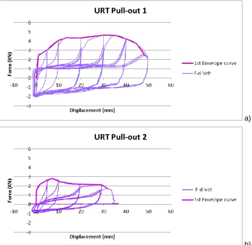
Figure 3.6 – Cyclic pull-out force-displacement diagrams; a) specimen PO1, b) specimen PO2. ... 35
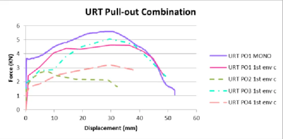
Figure 3.7 – Combination of F-d envelope curve graphs for all the pull-out tests. (URT: Unreinforced timber).. ... 36
Figure 3.8 – Cyclic pull-out force-displacement diagrams; a) specimen PO1, b) specimen PO2. ... 37
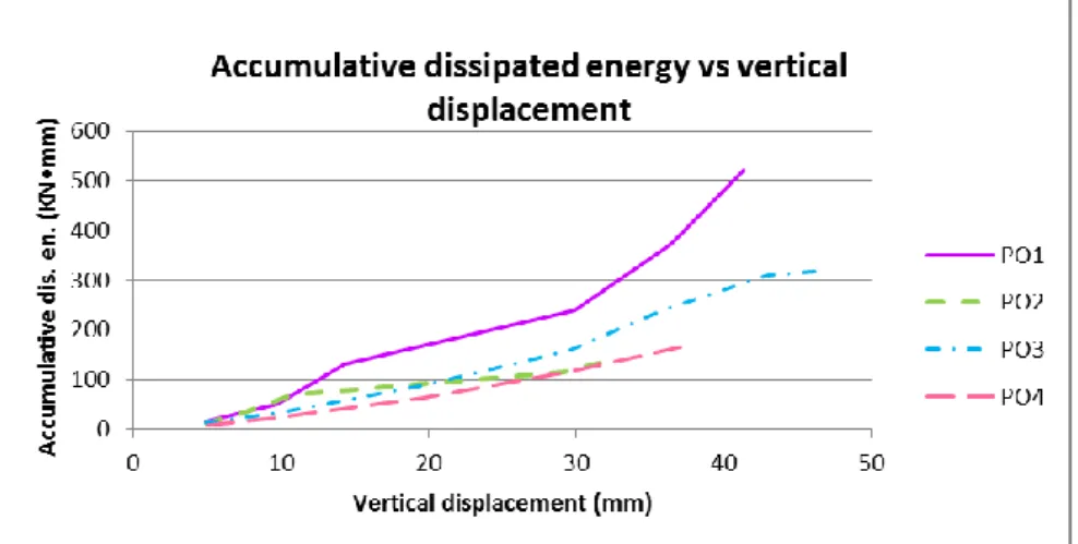
Figure 3.9 – Accumulative energy dissipated for increasing vertical displacements obtained for all the specimens.. ... 38
Figure 3.10 – The 3 cycles of step 5 (40mm) for specimen PO3. ... 38
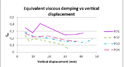
Figure 3.11 – Combination of the equivalent viscous damping graphs for all the pull-out tests. ... 39
Figure 3.12 – Combination of the cyclic stiffness graphs for all the pull-out tests.. ... 40
Figure 3.13 – Failure modes for timber connections in single shear and definition of t1 and t2 [29]. ... 42
Figure 3.14 – Test setup for in-plane cyclic tests; a) configuration and b) a photograph of the setup.. 45
Figure 3.15 – Positions of LVDTs for the in-plane cyclic tests. ... 46
Figure 3.16 – a) Vertical, sliding cracks parallel to the grain, b) Perpendicular to the grain, snapping crack forming arch, c) Perpendicular to the grain, snapping crack forming arch at the corner, d) Detached “tenon” of post, e) Imprint of post at the beam... 49
Figure 3.17 – Typical in-plane cyclic force-displacement diagrams for: a) a vertical load of 25KN and b) a vertical load of 50KN ... 50
Figure 3.18 – The hysteresis loop shapes of two consecutive steps (C5_25). ... 51
Figure 3.19 – Combination of F-d monotonic and envelope curve graphs for all the cyclic tests with: a) a vertical load of 25KN and b) a vertical load of 50KN. ... 51
Figure 3.20 – Representative horizontal-oop displacement diagrams for two cyclic tests with: a) a vertical load of 25KN (URT C3_25) and b) a vertical load of 50KN (URT C6_50). (Oop: out of plane). ... 52
Figure 3.21 – Representative horizontal-vertical displacement diagrams for two cyclic tests with: a) a vertical load of 25KN (URT C3_25) and b) a vertical load of 50KN (URT C6_50). ... 53
Figure 3.22 – Representative horizontal displacement configurations for two cyclic tests with: a) a vertical load of 25KN (URT C3_25) and b) a vertical load of 50KN (URT C8_50). ... 54
Figure 3.23 – Combination of the accumulative dissipated energy – drift% graphs for all the in plane cyclic tests with: a) a vertical load of 25KN and b) a vertical load of 50KN. ... 55
Figure 3.24 – The accumulative dissipated energy of all 3 cycles for C1_25. ... 55 Figure 3.25 – Combination of the equivalent viscous damping- drift % graphs for all the in plane cyclic tests with: a) a vertical load of 25KN and b) a vertical load of 50KN. ... 56 Figure 3.26 – Combination of the cyclic stiffness - drift % graphs for all the in plane cyclic tests with: a) a vertical load of 25KN and b) a vertical load of 50KN. ... 57 Figure 4.1 – a) Nail and screws, b) Bolt, nut and washer, c) Types of steel plates, d) Steel flat bar, e) Steel rods, f) Steel embedded connectors, g) Types of FRP, h) Types of FRP rods [40],[41]. ... 66 Figure 4.2 – Photos a) - i) show the application procedure of the GFRP sheets on the fixing point of the posts and j) the laterally placed screws. ... 69 Figure 4.3 – a) Self tapping screw, b) Wooden wedges were used to help follow the right angles, c) Difficulties were encountered when the screws were positioned through the posts. . ... 70 Figure 4.4 – Section configurations of the self-tapping screws positioning regarding front, back and upper point of view. (Dimensions in cm)... ... 70 Figure 4.5 – Configurations of the positioning for the “T” GFRP and the steel plates regarding front and back . (Dimensions in cm). ... 71 Figure 4.6 – a) Horizontal GFRP sheet applied first at front, b) Vertical GFRP sheet placed on top of the horizontal forming an upside down “T”, c) Vertical GFRP sheet applied first at the back, d) Straightening of the horizontally placed GFRP sheet using a rolling paint brush ... 72 Figure 4.7 – a) Drilling of holes for the bolts, b) Temporarily fixed plates in order to drill the holes for the bolts. The vertical plates were cut. c) Front side – d) Back side and positioning of the screws.. ... 73 Figure 4.8 – Section configurations of the NSM of steel rods regarding front, back and side point of view and configuration of the welded rods. (Dimensions in cm)... ... 74 Figure 4.9 – Photos a) - j) show the application procedure of the NSM steel rods. ... 75 Figure 4.10 – Photos a) Crack patterns for in plane cyclic tests, b) - d) Front, back and side view of posts for the 25kN compressive level, e) - g) Front, back and side view of posts for the 50kN pre-compressive level. ... 77 Figure 4.11 – Section configurations of the 3 solutions that were proposed for the prosthesis. On the right (3rd Solution) is the one that was finally applied. (Dimensions in cm)... ... 78 Figure 4.12 – a) - b) Application of paste glue for the prosthesis, c) Application of gel glue for the prosthesis, d) The gel was additionally filled with the help of a syringe, e) For the first two specimens on the left the prosthesis was placed with paste glue giving a better looking result, f) The positioning of the two screws at the prosthesis connection. ... 79
Figure 4.13 – Photos a) - f) show the application procedure of the GFRP sheets and CFRP strips and the bolt positioning at the specimen. ... 81 Figure 4.14 – a) - b) The vertical rods were reaching up to the height of the screws so they were slightly cut. ... 81 Figure 5.1 – Details of the damage patterns that were observed during the pull-out test of the specimen with “T” GFRP strengthening a) - c). ... 89 Figure 5.2 – Pull-out force-displacement diagram of the specimen with “T” GFRP strengthening. ... 89 Figure 5.3 - a) The specimen had no deformations, b) Graph showing the presence of beam uplift.. 90 Figure 5.4 - Pull-out force-displacement diagram of the specimen with steel plates strengthening. ... 91 Figure 5.5 – a) Front side of the specimen showing the deformations of the beam, b) Back side of the specimen and the effect of the uplifted screws, c) Graph showing the presence of beam uplift, d) The screws suffered permanent deformations.. ... 92 Figure 5.6 - Pull-out force-displacement diagram: a) retrofitted specimen with screws; b) corresponding unreinforced specimen. ... 93 Figure 5.7 – Photos a) – b) show the progressive damages of the NSM strengthened specimen during the pull-out test, d) Graph showing the presence of beam uplift. ... 94 Figure 5.8 - Pull-out force-displacement diagram of the specimen with NSM strengthening. ... 95 Figure 5.9 – Comparative diagram of the F-d envelope curves for all the retrofitted specimens, obtained from the pull-out tests. ... 95 Figure 5.10 - Accumulative dissipated energy for the increasing vertical displacements of all the retrofitted specimens, obtained from the pull-out tests.. ... 96 Figure 5.11 - Combination of the equivalent viscous damping graphs for all the retrofitted specimens, obtained from the pull-out tests. ... 97 Figure 5.12 - Combination of the cyclic stiffness graphs for all the retrofitted specimens, obtained from the pull-out tests.. ... 98 Figure 5.13 – Photos a) – d) show the progressive damage patterns that appeared during the in-plane cyclic tests of the damaged and strengthened with “T” GFRP specimens.. ... 99 Figure 5.14 – F-d graph for the strengthened with “T” GFRP specimens, which were subjected to in-plane cyclic tests and had: a) a vertical load of 25kN and b) a vertical load of 50kN.. ... 100 Figure 5.15 – Photos a) – d) show the progressive damage patterns that appeared during the in-plane cyclic tests of the strengthened with prosthesis and “T” GFRP specimens for a vertical load of 25kN. ... 101
Figure 5.16 – Photos a) – e) show the progressive damage patterns that appeared during the in-plane cyclic tests of the strengthened with prosthesis and “T” GFRP specimens for a vertical load of 50kN. ... 102 Figure 5.17 - F-d graph for the strengthened with prosthesis and “T” GFRP specimens, which were subjected to in-plane cyclic tests and had: a) a vertical load of 25kN and b) a vertical load of 50kN. 103 Figure 5.18 - Comparative diagram of the F-d envelope curves for all the retrofitted with “T” GFRP specimens, which were subjected to in-plane cyclic tests. ... 104 Figure 5.19 - Comparative diagram of the accumulative dissipated energy – drift % for all the retrofitted with “T” GFRP specimens, which were subjected to in-plane cyclic tests. ... 105 Figure 5.20 - Comparative diagram of the equivalent viscous damping – drift % for all the retrofitted with “T” GFRP specimens, which were subjected to in-plane cyclic tests.. ... 105 Figure 5.21 - Comparative diagram of the cyclic stiffness – drift % for all the retrofitted with “T” GFRP specimens, which were subjected to in-plane cyclic tests. ... 106 Figure 5.22 - Photos a) – e) show the progressive damage patterns that appeared during the in-plane cyclic tests of the strengthened with prosthesis and steel plates specimens for a vertical load of 25kN, f) Graph showing the lateral uplift of the prosthesis. ... 108 Figure 5.23 - Photos a) – c) show the progressive damage patterns that appeared during the in-plane cyclic tests of the strengthened with prosthesis and steel plates specimens for a vertical load of 50kN. ... 109 Figure 5.24 - F-d graph for the strengthened with prosthesis and steel plates specimens, which were subjected to in-plane cyclic tests and had: a) a vertical load of 25kN and b) a vertical load of 50kN, c) Comparative diagram of their F-d envelope curves. ... 110 Figure 5.25 - Comparative diagram of: a) the accumulative dissipated energy – drift%, b) the equivalent viscous damping – drift%, c) the cyclic stiffness – drift % for all the retrofitted with prosthesis and steel plates specimens, which were subjected to in-plane cyclic tests.. ... 112 Figure 5.26 - Photos a) – c) show the progressive damage patterns that appeared during the first in-plane cyclic test of the strengthened with prosthesis and NSM steel rods specimens for a vertical load of 50kN. ... 113 Figure 5.27 – Photos a) – c) show the progressive damage patterns that appeared during the second in-plane cyclic test of the strengthened with prosthesis and NSM steel rods specimens for a vertical load of 50kN. ... 113 Figure 5.28 – a)-b) F-d graphs for the strengthened with prosthesis and NSM steel rods specimens, which were subjected to in-plane cyclic tests with a vertical load of 50kN.(Case b) with lateral steel plates, c) Comparative diagram of their F-d envelope curves.. ... 115
Figure 5.29 - Comparative diagram of: a) the accumulative dissipated energy – drift%, b) the equivalent viscous damping – drift%, c) the cyclic stiffness – drift % for all the retrofitted with prosthesis and NSM steel rods specimens, which were subjected to in-plane cyclic tests.. ... 116 Figure 5.30 - Photos a)-c) show the progressive damage patterns that appeared during the in-plane cyclic test, for a vertical load of 50kN, of the strengthened with GFRP sheets and CFRP strips wrapped specimens: a), b) with a prosthesis, c) damaged.. ... 117 Figure 5.31 – a)-b) F-d graphs for the strengthened with GFRP sheets and CFRP strips wrapped specimens, which were subjected to in-plane cyclic tests with a vertical load of 50kN.(Case b) with a prosthesis, c) Comparative diagram of their F-d envelope curves.. ... 119 Figure 5.32 - Comparative diagram of: a) the accumulative dissipated energy – drift%, b) the equivalent viscous damping – drift%, c) the cyclic stiffness – drift % for all the retrofitted with GFRP sheets and CFRP strips wrapped specimens, which were subjected to in-plane cyclic tests.. ... 120 Figure 5.33 - Photos a)-d) show the progressive damage patterns that appeared during the pull-out tests of the strengthened with GFRP sheets and CFRP strips wrapped specimens: a) with a prosthesis, b)-d) damaged.. ... 122 Figure 5.34 – Graphs showing the uplifting at the bottom of the post for the induced uplifting displacements at the top of the post during the pull-out tests of the strengthened with GFRP sheets and CFRP strips wrapped specimens: a) damaged, b) with a prosthesis.. ... 122 Figure 5.35 - a)-b) F-d graphs for the strengthened with GFRP sheets and CFRP strips wrapped specimens, which were subjected to pull-out tests.(Case b) with a prosthesis, c) Comparative diagram of their F-d envelope curves. ... 123 Figure 5.36 - Comparative diagram of: a) the accumulative dissipated energy – drift%, b) the equivalent viscous damping – drift%, c) the cyclic stiffness – drift % for all the retrofitted with GFRP sheets and CFRP strips wrapped specimens, which were subjected to pull-out tests. ... 125
LIST OF TABLES
Table 3.1 – Mean values of superficial moisture content for beam, post and diagonal element ... 30 Table 3.2 – Pull-out test procedure and graph configuration ... 33 Table 3.3 – Final out-of-plane displacement measured at the end of the test in the deformed shape of the connection.. ... 37 Table 3.4 – Calculated initial stiffness for the first envelope curve of each test. ... 40 Table 3.5 – In-plane cyclic test procedure according to EN12512 [37]. ... 47 Table 3.6 – Calculated initial stiffness for the first envelope curve of each test with a vertical ... load of 25KN ... 58 Table 3.7 – Calculated initial stiffness for the first envelope curve of each test with a vertical ... load of 50KN ... 58 Table 4.1 – List of the in plane cyclic test specimens that will be retrofitted with a prosthesis... 77 Table 4.2 – List of all the specimens and the retrofitting solutions that were applied. ... 82 Table 5.1 – New procedure for the pull-out tests on the retrofitted specimens. ... 87 Table 5.2 - Calculated initial stiffness for the first envelope curve of all the retrofitted specimens, obtained from the pull-out tests. ... 97 Table 5.3 - Calculated initial stiffness for the first envelope curve of all the retrofitted with “T” GFRP specimens, which were subjected to in-plane cyclic tests. ... 106 Table 5.4 - Calculated initial stiffness for the first envelope curve of the retrofitted with prosthesis and steel plates specimens, which were subjected to in-plane cyclic tests. ... 112 Table 5.5 - Calculated initial stiffness for the first envelope curve of the retrofitted with prosthesis and NSM steel rods specimens, which were subjected to in-plane cyclic tests. ... 116 Table 5.6 – Calculated initial stiffness for the first envelope curve of all the retrofitted with GFRP sheets and CFRP strips wrapped specimens, which were subjected to in-plane cyclic tests.. ... 120 Table 5.7 – Calculated initial stiffness for the first envelope curve of all the retrofitted with GFRP sheets and CFRP strips wrapped specimens, obtained from the pull-out tests. ... 125
Chapter 1
1.1 General
Nowadays, buildings are mainly constructed with reinforced concrete, especially in areas affected by seismic events of a non-negligible magnitude, on a regular basis. Although the resistance capacity of this type of structures to seismic loads is undoubtedly high, there have been many cases where apart from the expected damages that are allowed during their designing, deformations surpassed those values by far, reaching even total failure and collapse. Furthermore, the seismic design regulations have to be reviewed quite often, since earthquakes do not always fall within the expected and predefined range. After all, concepts as seismicity and seismic hazard are relatively new [1].
On the other hand, traditional buildings made with empirical knowledge, much lighter materials and a clear disadvantage concerning strength and rigidity towards reinforced concrete, such as half-timbered structures, appear to have exceptionally good behavior with high ductility and relatively small damages, under seismic loads [2].
Half-timbered structures consist of a frame made of vertical, horizontal and diagonal wooden elements, which are joined together at the connections. A masonry infill of stones, adobes or bricks and mortar, is wedged in the areas formed between the wooden elements providing further stiffness [2].
Additionally, the declaration of certain traditional settlements, where this type of structure is found, as an important part of cultural heritage, leads to the need for their repairing and preservation, while changes in use require further strengthening and rehabilitation works. The same applies also to the unique case, of “Pombalino” buildings in Lisbon, Portugal, where this type of structures was used for the first time as a solution for higher seismic resistance of buildings, after the devastating effects from the earthquake of 1755 [3].
Experimental research has verified the importance of connections in half-timbered structures, as energy is dissipated mainly at these parts of the wall, while the infill masonry which is easily repairable can sustain relatively small damages [2], [4].
1.2 Objectives and methodology
Upon the completion of the experimental research on real size wall specimens, the need for further knowledge upon the mechanical behavior of traditional connections of half-timbered walls arose. As time for the conclusion of the Thesis was limited, only one of the connections was chosen to be studied: a lower corner connection where the post and beam are joined together through overlapping. The diagonal wooden element was not taken into consideration.
The behavior of this type of connection, during the in-plane quasi-static cyclic tests that were performed on the wall specimens, was governed by combined shear and bending. For this reason the main objectives of this work are centered in the understanding of the individual behavior of this type of
connections, aiming at obtained information that further enable its correlation to the behavior of the wall. For this, an experimental campaign was designed based on distinct types of load configurations, which are considered to be representative of the mechanical behavior of the connection under in-plane lateral loads. Therefore, in detail the major goals of the present work are:
Analysis of the results of pull-out tests to evaluate its performance while subjected to cyclic uplifting displacements.
Analysis of the results of in-plane cyclic tests regarding the studied connection to obtain information about the hysteresis properties under mixed flexure and shear loads.
Assessment of the results of distinct retrofitting solutions on the hysteretic performance of the connections.
1.3
Outline of the Thesis
After this introductory chapter, follows Chapter 2, which intends to familiarize the reader with the subject. Initially, a brief historical overview of the half-timbered structures is provided, along with the architectural description and construction details of a representative, traditional building in Greece. Furthermore, the connection typologies from the “Pombalino” walls are stated, while there is also a brief state of the art on the existing studies relevant to the studied traditional half-timbered walls and timber connections.
In Chapter 3, information about the geometry of the specimens along with some physical properties of the wood is provided. Moreover, the two different types of tests that were performed (pull-out and in-plane cyclic) on the unreinforced timber connections, as well as their setups, instrumentations and procedures are explained in detail. After each test, follows the analysis and commenting of the results and the clarification of certain calculations that took place. The results concerning the in-plane cyclic tests were grouped in relation to their pre-compression load level.
A detailed description of the retrofitting techniques that were decided to be applied after the observation of the damage patterns in the unreinforced specimens is given in Chapter 4. Moreover, there is a brief discussion of additional techniques, which were not used to strengthen the tested connections.
After the tests of the retrofitted connections were performed, the results that were obtained, were evaluated and they are presented in Chapter 5. Each test is analyzed separately, while for the in-plane cyclic tests the results were grouped according to the retrofitting technique which was applied.
Finally, the conclusions that derived from this experimental campaign, as well as recommendations for future studies regarding traditional connections in half-timbered walls, are listed in Chapter 6.
In order to help the reader follow the analysis, whenever there was a large number of graphs to be displayed, they were gathered in appendixes:
Appendix A: The figures with all the force versus displacement graphs of the pull-out and the in-plane cyclic tests were gathered in this section.
Appendix B: The figures with all the vertical versus out-of-plane displacement graphs of the pull-out tests were gathered in this section.
References
1] Penelis G.G., Kappos A.I., Earthquake resistant constructions from concrete (in Greek), ZITIS Publising, Thessaloniki 1999
[2] Kappos A.I., Kouris L.A., Modelling of Traditional Timber-Framed Masonry Structures (in Greek), 3rd National Conference on Earthquake Engineering and Engineering Seismology, 5-6 of November 2008, Paper No. 2013
[3] Paula R., Coias V., Rehabilitation of Lisbon's old seismic resistant timber framed buildings using innovative techniques, International Workshop on “Earthquake Engineering on Timber Structures”, Coimbra, Portugal, November, 2006
[4] Poletti E,, Vasconcelos G,, Oliveira D.V., Influence of infill on the cyclic behaviour of traditional half-timbered walls. In: Proceedings of International Conference on Rehabilitation and Restoration of Structures, Chennai, India, 2013.
Chapter 2
State-of-the-art for half-timbered walls
and their connections
2.1 Historical overview of the half-timbered wall structure
As wood is a material that is found extensively in nature, while it is also workable through easy ways and has good mechanical properties, it has been used in the construction of different types of structures for thousands of years.
Wooden elements have been used throughout time to create a whole structure, as huts or parts of it, like roofs, walls and floors. Specifically referring to walls, wooden elements have been used horizontally embedded within the walls, as they evolved vertically (ksilodesies in Greek, Figure 2.1a). Additionally, to make bearing walls, light structures were created with vertical, wooden, supporting elements that were filled with wattled reeds or nailed laths and covered with plaster (ksiloplekti
tichopiia or badgatotichos in Greek, Figure 2.1b) or by wooden frames which were filled with bricks,
rubble or adobe and usually covered with plaster (ksilopikti tichopiia or tsatmas in Greek, Figure 2.1c) [5]. The latter is the description of a half-timbered wall structure.
a)
b)
c)
Figure 2.1 – a) Horizontally, embedded, wooden elements within the wall, b) Wall made of vertical, wooden, supporting elements that were filled with wattled reeds or nailed laths and covered with plaster (ksiloplekti tichopiia), c) Half-timbered wall (ksilopikti tichopiia) [6].
Chronologically, the first two story half–timbered wall structure can be found in the less known archaeological site of Herculaneum, which is close to Pompeii, Italy and was also buried under lava
after the eruption of Mount Vesuvius’ volcano in 79AD. According to Vitruvius’ masonry construction typologies the structure could be described as Craticii or Opus Craticium [7].
Eventually, due to the simplicity of its construction and the use of cheap materials, this structure spread throughout the Mediterranean basin, as well as the rest of Europe, parts of Asia and South America. Since the 8th century until recently it has been greatly used in Turkey, where it is called himis (Figure 2.3a) and in Greece, tsatmas is a very common, traditional structure ever since the Byzantine era (Figure 2.3b) [7],[8]. Other local names to describe the studied structure would be (Figure 2.2):
colombage in France, fackwerkbau in Germany, telar de medianeria in Spain, half-timber in Britain, dhajji-dewari in Kashmir, India (Figure 3-c) and bindingverk in Scandinavia (Figure 2.3d) [8], [9].
In Central America a variation between half-timbered walls and the ones created by vertical, wooden, supporting elements that were filled with wattled reeds or nailed laths and covered with plaster (named
bagdadi in Turkey and Greece and quincha in Peru) can be found in Nicaragua, called taquezal or
“pocket” system and in El Salvador, called bahareque. In this case the “pockets” that were formed as the wooden laths or bamboos were nailed across the studs, were then filled with layers of small stones or adobe. Finally the wall would be covered with plaster [7].
It is noteworthy, that the first time, half-timbered walls were used because of the observation of their seismic resistance ability, was after the earthquake of Lisbon, Portugal in 1755, and the one in Calabria, Italy in 1783. An anti-seismic inner wall system of half-timbered walls was created in both cases, in order to resist horizontal loads and dissipate energy, while it was also tied to the outer stone masonry walls in order to prevent their out-of-plane overturning. The developed systems were named
gaiola (=cage) or Pombalino construction and Casa Baraccata respectively [7],[3].
a) b) c)
d)
Figure 2.3 – a) Himis in Turkey, b) Ksilopikti tichopiia in Athens, Greece, c) Dhajji-dewari in Kashmir, India, d) Bindingverk in Sweden [9],[10],[7],[8].
2.2 Architectural description of a typical half-timbered building in Greece
The historical building which is described below in detail is located in Ractivan Street 23, Thessaloniki, Greece. The upper part of the city, called Ano Poli, has been declared as a traditional settlement and most of its noticeable buildings, where created while the city was under the reign of the Ottoman Empire, since 1432 and for almost five centuries after, but the buildings are mainly from the 19th century [11].2.2.1 Foundation
The so called shallow foundation is made of rough stones and clay mortar. The stones are laid in the perimeter of the building, in a pit that has a depth of no more than 60cm and a width of 70÷80cm depending on the width of the masonry walls of the ground floor, which were usually made of stone (Figure 2.4) [11].
2.2.2 Ground floor
Usually the bearing walls of this floor would be made of stone masonry, but the lighter half-timbered structure can also be seen here in some occasions [6]. The structural materials are limestones from the area of Thessaloniki and clay mortar mixed with hay. The stones are slightly hewed in order to form a proper laying surface for the ones lying over and underneath them. The joints are continuous only concerning the horizontal direction. These joints are no bigger than 2cm and in some parts they have been filled with small rubble stones or tile pieces. The width of the wall is between 60÷70cm and at a height of 70cm, as well as at the highest point of the wall, there are horizontally embedded, wooden elements (Figure 2.4) [11].
Figure 2.4 – Structural detail of the stone masonry wall and the foundation [11].
2.2.3 Upper storeys
2.2.3.1 Half-timbered structureAll the bearing walls of the upper storeys are half-timbered structures. They consist of a frame made of horizontal, vertical and diagonal wooden elements jointed together in plane. The first horizontal wooden base-beam is nailed upon the wooden floor boards which are right above the wooden beams of the floor. The nails used are placed in an inclined way and they are made of steel with a square section. The vertical columns are nailed upon the horizontal base-beam without having a mortise and tenon connection, while the stabilization of the connections is ensured by the existence and wedging of the appropriately shaped, diagonal elements. At the highest point of the wall the beams are supported on the columns through an inserted, wooden element that has a mortise and tenon connection with its ends formed into chamfers. The infill masonry includes adobes or bricks, mud, small stones and pieces of tiles in a clay mortar mixed with hay. The width of this type of wall along with the coating is around 20cm (Figure 2.5) [11].
Figure 2.5 – Structural detail of the half-timbered wall [11].
2.2.3.2 Inner walls
Light, wooden walls were used to separate the interior spaces with different uses. These structures which are called bagdadi in Turkey and also in Greece are constructed by wooden beams and columns that form a frame, where wooden laths of an approximate thickness 1,5÷2cm and width 3÷5cm were nailed on both columns with a vertical gap of 2cm. These gaps would ensure better adhesion and stabilization of the coating that was applied afterwards. Another technique was the placement of wattled reeds instead of nailed laths (Figure 2.6) [11],[6].
2.2.3.3 Jetty
When the room of an upper floor has greater dimensions than its inferior and its projection protrudes towards the pavement, it creates an architectural differentiation which is called, jetty or overhanging upper storey [7]. In this case the floor beams extend further than the building line, as cantilevers. At the edge of the beams, there is a beam that connects them in a lateral way, and which redistributes the loads to the struts that support the jetty. The struts end at the outer wall of the lower floor diagonally and they can have different architectonic variations (Figure 2.7) [11]. Additionally, jetties serve a structural purpose, as they apply a compressive force to the walls below them, which adds to their strength against lateral forces [7].
Figure 2.7 – Structural detail of the jetty [11].
2.2.4 Floor
It was common practise, for the ground floor to be the previously existing earth, which would be leveled with shovels. On a frequent basis some water, mud and manure was applied on the floor to prevent dust from rising and to keep its surface smooth [12].
The wooden floors of the upper storeys, consist of the beams that have a section of 7x15 (cm), placed every 40÷50cm, in a way parallel to the small side of the wall. It should be mentioned that traditional houses usually had a rectangular shape, with a good orientation regarding energy-saving [12]. The floor boards have a width of 18÷22cm and a thickness of 2,5cm. In the intersection between the floor and the wall there is a skirting board with a height of 7cm. The ceiling is also covered with wooden boards and a decorative wooden strip around the perimeter of the rooms (Figure 2.8) [11].
Figure 2.8 – Structural detail of the wooden floor [11].
2.2.5 Roof
The building has a wooden roof with a height of 1,95m and an inclination that ranges between 50÷55%. The ridge beam, the tie beams of the ceiling from the underlying floor, the beams that form the half -timbered wall frames, in the perimeter of the roof plan and the collar beams that exist along the height between the previous, are the horizontal elements of the wooden trusses. Additionally, there are main and secondary posts positioned vertically while rafters and wooden boards are placed inclined, concluding the wooden frame structure of the roof. The roof is covered with tiles (Figure 2.9) [11].
2.2.6 Function and distribution of spaces
Traditional buildings that date back to the 19th century bear common features, such as a rectangular plan shape, two or three storeys and rooms arranged in a row. Access was usually possible through the transitional room in the middle of the floor plan, which served as a hallway or a living room and leaded to the rooms on each one of its sides [11].
The openings were fewer on the ground floor, since it was generally meant to accommodate secondary uses, as stables or storage rooms [6]. Additionally, openings are not found distributed equally on each side of the building, which could lead to the assumption that local constructors had empirically observed that it was more efficient, as far as it concerned energy losses to minimize the presence of openings on the north side of the building, while on the contrary it was feasible for the south side [12].
The upper floors housed the social and private life of the family, while additional, roughly constructed buildings in the surrounding area of the main building, served as oven or secondary kitchen, laundry room, toilets or storerooms [11],[12].
2.3 Description of the connection typologies in half-timbered frames
The architectural description of a half-timbered wall in Greece has been provided in a previous paragraph (See 2.2.3.1).
Nevertheless, the experimental part of this project will be referring to the “Pombalino” buildings of Lisbon that bear the “gaiola” or “cage” system, therefore it is essential that the main differences of these two systems are stated.
While, the half-timbered frame walls were used in Greece, to form the exterior walls of the upper storeys as a rather economical construction that they intuitively and empirically related to strength and flexibility, in Lisbon they were used in the interior of the buildings as a previously observed seismic resistant system, after the earthquake of 1755. The latter system was being knowingly used in order to make the construction resistant to horizontal loads and to dissipate substantial amounts of energy and prevent the overturning of the external stone masonry walls. In fact, the two-directional vertical bracing system of timber framed walls was connected to the façade pilasters, which were confined by horizontally embedded wooden elements (Figure 2.11) [3].
Since, the “gaiola” system was in the interior of the buildings, it had a lower number of openings, which means that it had more diagonal wooden members that contributed to a higher stiffness against horizontal loads in plane [10]. Additionally, the positioning angle of the diagonal elements, in the case of “gaiola” was usually 45º, which was easily achieved in the absence of openings while in the Greek system this angle varies. The infill material in Lisbon consisted mainly of rubble masonry made of small stones and ceramic elements set in lime mortar and there was no use of adobes or bricks as in the case of Greece. Another difference between these two cases is the number of floors, which was usually 4÷5 in Lisbon, while in Greece 2÷3 which influences the applied vertical loads in each case [3], [6].
The presence of a mortise and tenon connection between the posts, beams and diagonal parts of the timber-framed walls, was not very common in Greece [11], although in some cases a round tenon of approximately 6cm was connecting the vertical posts to the horizontal elements [10]. However, in common practice the vertical posts were connected to the horizontal elements by a single iron nail, while the diagonal elements were usually wedged in the corners that were formed by the vertical posts and the horizontal elements and an iron nail was used sometimes to secure that they stayed in place [10], [11]. On the other hand, in case of the “Pombalino” structure, the timber elements that constituted it, where usually notched together with crossed edge half lap or edge half lap through joints (Figure 2.12) or connected by nails or iron ties, while there have also been cases where dovetail connections were present (Figure 2.13) [13], [14], [16] .
More precisely, three different types of connection typologies can be identified in the “gaiola” system for the case where a wall with three posts and three beams in considered along with its diagonal bracing elements (Figure 2.12):
i. The corner connection, where the post is connected to the beam with an edge half lap through joint and a nail, although there have been cases where only the vertical elements were cut in half thickness, while the beams maintain their original form [15].
ii. The central connection and
iii. The connection between the diagonal elements, where the timber elements are connected by a crossed edge half lap joint (and a nail in the case of ii).
Figure 2.12 – Configuration and structural details of the connections in the “Pombalino” structure [4], [14].
Figure 2.13 – Configuration and structural details of dovetail connections in a “Pombalino” structure [16].
2.4 Existing studies on half-timbered walls
The attempt to have a better insight and analyze the seismic behavior of half-timbered walls is a difficult task, as it involves material and geometrical dissimilarities, while there are no distinct regulations and standards to take into consideration. This leads to inevitable assumptions and simplifications and the resort to limited, relevant information in the codes [17].
Seismic evaluation of such structures is attainable through various ways:
From observations in the pathology of buildings that have been affected by a recent earthquake. This can be regarded as an “experiment” in the true scales of space and time [18]. Indeed, such inspections of buildings in the past have provided the following conclusions: i) First appears detachment of the infill masonry from the timber frame, while at the
same time occurs separation and falling of the coating,
ii) Subsequently, cracking of the infill masonry and possible falling out-of-plane and iii) At the end damages take place at the timber frame, which could lead to its collapse. It is important to clarify that the last type of damage can be found in cases where buildings have been out of use and neglected for years and that generally, the damages that are found tend to be less when the materials had better quality and the engineering efficacy was adequate [2],[9],[19].
Through numerical modeling with the use of different, available software such as Diana, Sap, ABAQUS, ANSYS etc. The studied structure is simulated in the form of finite elements with
certain degrees of freedom and mathematical functions and they have to be chosen carefully in order to give the correct results, while the analyst should be able to evaluate the final results and realize the existence of probable mistakes [18].
Nevertheless, it is challenging to appropriately simulate half-timbered walls, as some of the problems that rise are:
i) The sliding of the diagonal timber elements which are in tension, when seismic horizontal forces are implemented. This action leaves these elements almost in disuse.
ii) The connections should not be assumed as rigid and their flexibility has to be taken into account.
iii) The existence or not of openings and the adequate reproduction of the surrounding timber frame.
iv) Finally, the consideration or not of the masonry infill and the material properties that will be used [2],[17].
Finally, helpful information to the scientific community is provided through the performance of experiments on real size walls which are either manufactured [4],[15] or removed from buildings (Figure 2.14) [7]. In the first case it is possible to perform tests on walls with or without infill and openings as well. Additionally, it is possible to examine the cases of repairing, strengthening and rehabilitation [20],[21]. Such a research is ongoing at the moment at the University of Minho in Portugal (Figure 2.15) [4].
Scale models of this type of walls, unreinforced and with reinforcement, have also been tested in the past in diagonal compression [28] and in plane cyclic tests [29].
a) b)
Figure 2.14 – a) Removed wall from “Pombalino” building and tested for strength and stiffness in the Portuguese National Lab by Coias e Silva, b) F-d graph of one from the three walls that were tested, which shows that structural integrity was not lost [7].
a) b) Figure 2.15 – a) Timber-framed wall without infill tested at the University of Minho, Portugal, b) Corresponding F-d graph for the lower considered vertical load (25KN) [4].
2.5 Existing studies on relevant timber connections
While the timber frame of the studied walls could be described as a wooden truss [17], the connection typologies between half-timbered walls and roof trusses, for example, are quite different.
The background literature in overlapping connections is very limited, as opposed to the one referring to tests and strengthening techniques applied on typical carpentry connections found in traditional roof trusses such as single step frontal (Birdsmouth) joint, single posterior step (Birdsmouth) joint and double step joint for the connection between tie beams and rafters (Figure 2.16a-c) [22],[23],[24], or mortise and tenon connections for the struts (Figure 2.16 d) [25],[26],[27].
a) b)
c) d)
Figure 2.16 – a) Single step frontal joint, b) Single posterior step joint, c) Double step joint and d) Tapered mortise and tenon joint [22], [25].
This indicates that experimental campaigns are necessary in order to provide engineers with sufficient knowledge regarding the mechanical behavior of overlapped connections that are representative of half-timbered walls. According to EC8, for wooden trusses with nails in their joints, only the area of the connection will be considered to dissipate energy, while their diagonal members can be taken into consideration as linearly elastic [17].
Therefore, once all the connection typologies are tested and their results are evaluated and verified through numerical analysis, it could be possible to correlate the results with the ones from timber-framed walls that have been tested without their infill.
References
[2] Kappos A.I., Kouris L.A., Modelling of Traditional Timber-Framed Masonry Structures (in Greek), 3rd National Conference on Earthquake Engineering and Engineering Seismology, 5-6 of November 2008, Paper No. 2013
[3] Paula R., Coias V., Rehabilitation of Lisbon's old seismic resistant timber framed buildings using innovative techniques, International Workshop on “Earthquake Engineering on Timber Structures”, Coimbra, Portugal, November, 2006
[4] Poletti E,, Vasconcelos G,, Oliveira D.V., Influence of infill on the cyclic behaviour of traditional half-timbered walls. In: Proceedings of International Conference on Rehabilitation and Restoration of Structures, Chennai, India, 2013.
[5] Stilianidis K., Ignatakis C., Masonry Structures(according to Eurocodes 6 and 8) (in Greek), Thessaloniki 2010
[6] Morphology - Rhythmology, Theory of Architectural Forms & Rhythms, Traditional Architecture (in Greek), Student Notes from Democritus University of Thrace, Ksanthi
Available at:
http://morfologia.arch.duth.gr/3o_etos/3o_exam_VI/paradosiaka.pdf
(7.7.2013) [7] Langenbach R., From “Opus Craticium” to the “Chicago Frame”: Earthquake-ResistantTraditional Construction, International Journal of Architectural Heritage (2007),1:1, 29 — 59 [8] Copani P., Timber-Frame Buildings in Scandinavia: High Deformation Prevent the System from
Collapse, ICOMOS IWC - XVI International Symposium: From Material to Structure - Mechanical Behaviour and Failures of the Timber Structures, Florence, Venice and Vicenza, 11th -16th November 2007
[9] Gülkan P., Langenbach R., The earthquake resistance of traditional timber and masonry dwellings in turkey, 13th World Conference on Earthquake Engineering, Vancouver, B.C., Canada, August 1-6, 2004, Paper No. 2297
[10] Tsakanika-Theohari E., Mouzakis H., A post-byzantine mansion in Athens. The restoration project of the timber structural elements, World Conference on Timber Engineering 2010
[11] Anastasiadis C., Papadopoulos D., Restoration and energy efficiency of a historical building in Ano Poli, Master Thesis, Civil Engineering Dept., Aristotle University of Thessaloniki, 2010 [12] Koukouviki A.M., Inspection of insulation efficiency of a rural area residence in Megalo Seirini,
Grevena, Greece, according to the Regulation of Energy Performance of Buildings and suggestions on its improvement (in Greek), Master Thesis, Civil Engineering Dept., Aristotle University of Thessaloniki, 2011
[13] Cardoso R., Lopes M., Bento R., Seismic evaluation of old masonry buildings. Part I: Method description and application to a case-study, Engineering Structures 27: (2005), 2024–2035 [14] The Hobbit House Illustrated Glossary of Woodworking terms - Joinery terms:
http://www.hobbithouseinc.com/personal/woodpics/_joineryterms.htm
(7.7.2013)[15] Meireles H.A., Seismic vulnerability of Pombalino buildings. PhD Thesis. UTL, Instituto Superior Tecnico, Lisbon 2012
[16] Mascarenhas J., Construction systems – V (in Portuguese). Livros Horizonte, Lisbon 2004 [17] Ignatakis C., Eftichidis S., Investigation of masonry infilled timber structures-Modelling proposal
and analysis procedure (in Greek), 3rd National Conference on Earthquake Engineering and Engineering Seismology, 5-6 of November 2008, Paper No. 2072
[18] Roca P., Kabele P., Lourenco P., MSc SAHC Lecture, SA2.1 Purpose and Possibilities of Structural Analysis, UNIPD, Padova, Italy, 2012-2013.
[19] Gülhan D., Güney I.O., The behaviour of traditional building systems against earthquake and its comparision to reinforced concrete frame systems; experiences of Marmara earthquake damage assesment studies in Kocaeli and Sakarya.
Available at ICOMOS International Wood Committee :
http://www.icomos.org/iiwc/seismic/Gulhan.pdf
(7.7.2013)
[20] Goncalves A.M., Ferreira J.G., Guerreiro L., Branco F., Seismic retrofitting of Pombalino “frontal” walls, World Conference of Earthquake Engineering, Lisbon 2012, Paper No. 5129 [21] Poletti E., Vasconcelos G., Seismic behaviour and retrofitting of timber frame walls. International
conference on structural health assessment of timber structures (SHATIS’13) 4 - 6 September 2013, Trento, Italy (accepted).
[22] Branco J., Influence of the joints stiffness in the monotonic and cyclic behavior of traditional timber trusses. Assessment of the efficacy of different strengthening techniques, Ph.D. Thesis, Civil Engineering Dept., University of Minho, Portugal 2008
[23] Palma P., Garcia H., Ferreira J., Appleton J., Cruz H., Behaviour and repair of carpentry connections – Rotational behaviour of the rafter and tie beam connection in timber roof structures, Journal of Cultural Heritage 13S (2012) S64–S73
[24] Parisi M.A., Cordie C., Mechanical behavior of double-step timber joints, Construction and Building Materials: Volume 24, Issue 8, August 2010, Pages 1364–1371
[25] Koch H., Eisenhut L., Seim W., Multimode failure of formfitting timber connections -Experimental and numerical studies on the tapered tenon joint, Engineering Structures 48 (2013) 727–738
[26] Feio A., Lourenco P., Machado J., Testing and modeling of a traditional timber mortise and tenon joint, Materials and Structures: DOI 10.1617/s11527-013-0056-y, 2013
[27] Shanks J.D., Walker P., Experimental performance of mortise and tenon connections in green oak, The Structural Engineer – 6 September 2005, p.40-45
[28] Cruz H., Moura J.P., Machado J.S., The use of FRP in the strengthening of timber-reinforced masonry load-bearing walls, Historical Constructions, Guimaraes, 2001, p.847-856
[29] Pilaon P., Experimental cyclic behavior of timber shear walls, SAHC Master Thesis, Civil Engineering Dept., University of Minho, Portugal 2010
![Figure 2.4 – Structural detail of the stone masonry wall and the foundation [11].](https://thumb-eu.123doks.com/thumbv2/123dok_br/17758226.835270/37.892.200.643.392.716/figure-structural-stone-masonry-wall-foundation.webp)
![Figure 2.9 – Axonometric configuration of the wooden frame structure of the roof [11]](https://thumb-eu.123doks.com/thumbv2/123dok_br/17758226.835270/40.892.205.729.730.1036/figure-axonometric-configuration-wooden-frame-structure-roof.webp)
![Figure 2.11 – Axonometric configuration and structural details of the “Pombalino” structure [3]](https://thumb-eu.123doks.com/thumbv2/123dok_br/17758226.835270/42.892.134.803.808.1077/figure-axonometric-configuration-structural-details-pombalino-structure.webp)
![Figure 2.12 – Configuration and structural details of the connections in the “Pombalino” structure [4], [14]](https://thumb-eu.123doks.com/thumbv2/123dok_br/17758226.835270/43.892.120.729.670.1032/figure-configuration-structural-details-connections-pombalino-structure.webp)
![Figure 2.16 – a) Single step frontal joint, b) Single posterior step joint, c) Double step joint and d) Tapered mortise and tenon joint [22], [25]](https://thumb-eu.123doks.com/thumbv2/123dok_br/17758226.835270/46.892.136.794.142.380/figure-single-frontal-single-posterior-double-tapered-mortise.webp)