Proceedings of the 7th International Conference on Safety and Durability of Structures
ICOSADOS 2016
May 10 - 12, 2016, UTAD, Portugal
APPLICATION OF EUROCODES 0 AND 1 – COMPARISON WITH SIA 260
AND 261 SWISS STANDARDS
Carlos Moreno1,2 a, Ricardo Branco3, b and Débora Ferreira3,4 c
1University of Applied Sciences and Arts of Western Switzerland – Geneva, Switzerland
2inPACT, Institute for Landscaping, Architecture, Construction and Territory – Switzerland
3Polytechnic Institute of Bragança (IPB-ESTiG) – Bragança, Portugal
4C-MADE, University of Beira Interior – Covilhã, Portugal
a[email protected], b[email protected], c[email protected]
Keywords: EN, SIA, snow load, load combinations.
Introduction
The construction sector has been evolving to meet the growing needs of populations. Safety is one of the fundamental factors in the construction and therefore the development of harmonised structural standards and design codes ensure this safety. With the European Union enlargement which leads to the borders fading, one can comprehend the rising concern in bringing together design codes for the structural design and verification of buildings and civil engineering structures so that a qualified professional is able to apply and design in any of the Member States. Thus, the European Committee for Standardisation (CEN) was designated to establish a set of coordinated and common technical specifications that will ultimately replace the differing rules in the various Member States in order to stimulate European internal market. This suite of standards is known as the Structural Eurocode and comprises 10 standards generally consisting of a number of parts. Hence, Eurocode (basis of structural design) [1] - also known as Eurocode 0 - and Eurocode 1 (actions on structures) [2] are analysed in the scope of this study.
The former EN (European Norm) 1990 establishes and provides comprehensive information and guidance for all the Structural Eurocode, the overall principles and requirements for safety and serviceability, and supplies the information for safety factors for actions and the rules for the combination of actions, i.e. the probabilistic scenario of a particular action occurrence simultaneously with another load event. The later code EN 1991 provides comprehensive information and guidance on all actions that are normally necessary to consider in the design of building and civil engineering structures.
Tesco Store’s roof in Scunthorpe, North Yorkshire, in the UK (Fig. 1d).
a) b) c) d) Fig. 1.Recent structural collapses due to snow accumulation (Sources: Reuters, CSBnews, CNN,
dailymail.co.uk)
To clarify the current structural design rules in another country contrasting with those used in Europe and in Portugal is certainly an asset. Thus, the present work aims to contribute towards establishing a bridge between two distinct normative realities: European Union in general, particularly Portugal, and Switzerland. Current paper is issued from a vast work developed elsewhere [3].
A review analysis is conducted. The initial approach was based on a parametric analysis of the design codes, the goal being the inclusion of EN 1990 and EN 1991 as well as the use of the Swiss structural codes (SIA 260 and 261). This purpose was barred by the lack of Swiss National Annexes, disallowing to establish a direct assessment due to the absence of nationally determined parameters (NDPs). A comparison of the two design code sets based on the consideration of similar climatic places was afterwards developed considering the same altitude and similar climacteric parameters between two chosen locations. The cities of Bragança and Lausanne were selected in the Portuguese and Swiss territories respectively. The European standards EN 1990 and EN 1991 apply for the former while Swiss SIA 260 [4] and 261 [5] regulations apply for the later.
Combination of actions
Current design codes are generally based on design situations representing the real conditions that occur during the execution and use of a structure allowing for reliability requirements differentiation based on the consequences of failure, for which the design will demonstrate that relevant limit states are not exceeded. Two different types of limit states are considered namely Ultimate Limit State (ULS) at which the limit of structural safety is reached, and Serviceability Limit State (SLS) that correspond to conditions beyond which specified service requirements for a structure or structural element are no longer met.
In general, actions are sets of forces, pressures, imposed displacements or accelerations and are classified regarding their variation in time as follows: permanent actions (G), variable actions (Q) and accidental actions (A).
A comparative analysis on ULS and SLS for both the European and Swiss design codes is carried out in the following. Further guidance may be found in [6]. It is important to note that for all the load combinations only the less favourable effect (causing the most adverse effect on the structure) of the permanent and variable actions are considered. For easier comparison, following expressions were harmonised according to the notation of the symbols as defined by EN 1990. In the following expressions:
denotes “to be combined with”
denotes “the combined effect of”Ultimate limit state
multiplied by the appropriate safety factor) and the design resistant capacities (characteristic values divided by the proper safety factor) of the materials properties, so that the several structural elements meet the basic condition for structural safety expressed as follows:
d d R
E (1)
where:
Ed is the design value of the effect of actions, and Rd is the design value of the corresponding resistance.
According to EN 1990, the design value of the effect of actions (fundamental combination) can be obtained as follows:
1 , , 0 , 1 , 1 , 1 , , i i k i i Q k Q j j k j Gd G Q Q
E (2)
In expression (2) it is assumed that a number (1+i) of variable actions are acting simultaneously. The variable action Q1 is the leading variable action applied in order to obtain the most unfavourable effect and is therefore taken into account with its characteristic value Qk,1multiplied by the corresponding partial safety factor γQ,1. The i remaining variable actions (accompanying variable actions) which may act simultaneously with the leading variable action are taken into account with their combination value ψ0,iQk,i i.e. their characteristic value reduced by the relevant reduction factor ψ0,i and are multiplied by the appropriate safety factor γQ,i in order to obtain the design values.
In SIA 260 design code the fundamental combination rule to obtain the ULS design value of the effect of actions is as follows:
1 , , 0 1 , 1 , 1 , , i i k i k Q j j k j Gd G Q Q
E (3)
Comparing expressions (2) and (3) it is clear that no difference can be pointed out regarding permanent loads, partial safety factor γQ,1 taking the same value, and only leading variable action is increased for safety purpose in both design codes. However, it should be noted that EN 1990 explicitly provides the possibility for the partial safety factor for leading variable action to be different from the one used for the accompanying variable actions.
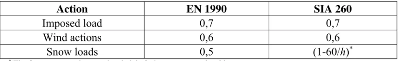
Concerning permanent actions, the total self-weight of structural and non-structural members is taken as a single action when combinations of actions are being considered. Apparently, major difference resides in dealing to the accompanying variable actions which are not multiplied by the appropriate partial safety factor in the Swiss code. As the same reliability level is mandatory, one can foresee that SIA 260 reduction factors ψ0 are greater than the EN 1990 ones. Table 1 gives those factors for several actions.
Table 1.Recommended values of reduction factor ψ0 for residential buildings
Action EN 1990 SIA 260
Imposed load 0,7 0,7
Wind actions 0,6 0,6
Snow loads 0,5 (1-60/h)*
* The factor may not be negative, height h above mean sea level in m.
One can observe identical combination factors for imposed loads and wind actions. Regarding snow loads, it can therefore be pointed out that for altitude h greater than 120 m the SIA 260 reduction factor is persistently greater than the corresponding EN 1990 value.
Service limit state
From a general point of view, SLS verification is expressed as:
d d C
where:
Ed is the design value of the effects of actions specified in the serviceability criterion, determined on the basis of the relevant combination, and
Cd is the limiting design value of the relevant serviceability criterion.
Three categories of combinations of actions are proposed in EN 1990 and SIA 260 as indicated below:
- The characteristic (or rare) combinations used mainly in those cases when exceedance of a limit state causes a permanent local damage or permanent unacceptable deformation, generally associated with a very short period of time limit state (a few hours) and an irreversible serviceability limit state;
- The frequent combinations used mainly in those cases when exceedance of a limit state causes local damage, large deformations or vibrations which are temporary (approximately 5% of structure intended life) and a reversible serviceability limit state;
- The quasi-permanent combinations used mainly when long-term effects are of importance (at least half the structure intended life) causing a reversible serviceability limit state.
Both the EN 1990 and SIA 260 standards set up identical formulations for the SLS load combinations, depending on the time extent of action, as indicated below:
a) Characteristic combinations:
1 , , 0 1 , 1 , i i k i k j j kd G Q Q
E (5)
b) Frequent combinations:
1 , , 2 1 , 1 , 1 1 , i i k i k j j kd G Q Q
E (6)
c) Quasi-permanent combinations:
1 , , 2 1 , i i k i j j kd G Q
E
(7)
Table 2 reproduces the recommended values for ψ1 and ψ2 factors for the more common actions in buildings.
Table 2.Recommended values of reduction factors ψ1 andψ2 for residential buildings
Action EN 1990 SIA 260
ψ1 ψ2 ψ1 ψ2
Imposed load 0,5 0,3 0,5 0,3
Wind actions 0,2 0,0 0,5 0,0
Snow loads 0,2 0,0 (1-250/h)* (1-1000/h)*
* The factors may not be negative, height h above mean sea level in m.
Once more, main difference exists in snow load’s frequent and quasi-permanent reduction factors. SIA 260’s ψ1 and ψ2 factors are consistently greater than the corresponding EN 1990 values used in the case of height h above the sea level higher than 312,5 m and 1000 m respectively.
Snow load on the ground
The magnitude and form of the snow load are influenced by the climate, the topography, the location and the shape of the structure as well as by the wind exposure, the type of cladding and the heat transfer at the roof surface.
Snow load according to EN 1991
The slope of the roof determines the shape coefficient to be taken into account, since this control the amount of snow that can accumulate. If the roof slope is high the snow slides without accumulation, while a flat roof collects an amount of snow comparable to the one to be considered at the ground level. The slope of the roof plays thus a crucial role in respect to the accumulation of snow. Accordingly, in countries where there are large snow falls, the roofs exploit steeper slopes compared to countries where the occurrence of snow is considered as being rare.
In the absence of wind, snow is deposited on the roof in a balanced way and a uniform cover is generally formed. Wind can also be relevant because snow particles can be picked up from the snow cover and redeposited on the lee sides or swept away from the roof preventing the snow accumulation. Further guidance may be found in [7].
Snow load at ground level is dealt with in the Portuguese National Annex of part 1-3 of EN 1991 [2]. The characteristic value of the snow load on the ground sk (in kN/m2) should hence be determined according to the following equation:
2
500
1 h
C
sk z (8)
where:
Cz is a zone-dependent factor (equal to 0,30 for zone Z1, 0,20 for zone Z2 and 0,1 for zone Z3, obtained from the national snow map as indicated in Fig. 2), and
h is the location altitude in m
The Portuguese territory is divided into three homogeneous climatic regions, through the analysis of the correlation presented by ground snow load characteristic values versus altitude of the relative weather station, as illustrated in Fig. 2.
Snow load on roofs is dealt with in part 1-3 of EN 1991 [2]. The characteristic value of the snow load on roofs s (in kN/m2) should be determined according to:
k t e iC Cs
s (9)
where:
μi is the typical snow load shape coefficient (or roof shape factor), taking into account the difference between the snow load on roofs and that on horizontal ground,
Ce is the exposure coefficient (see Table 3 below), Ct is the thermal coefficient, and
sk is the characteristic value of snow load on the ground.
Fig. 2.Distribution of Cz factor in Portugal [2]
Portuguese National Annex of part 1-3 of EN 1991 [2] where a value being Ct = 1 is recommended.
Table 3.Recommended values for Ce coefficient for different topographies [2]
Topography Ce
Windswept for flat unobstructed areas exposed on all sides without, or with little,
shelter afforded by terrain, higher construction works or trees 0,8
Normal for areas where there is no significant removal of snow by wind on
construction work, because of terrain, other construction works or trees 1,0
Sheltered
for areas where the construction work being considered is considerably lower than the surrounding terrain or surrounded by high trees and/or surrounded by higher construction works
1,2
Snow load according to SIA 261
SIA 261’ snow formulation is quite similar to the EN 1991. The provisions do not apply to structures at an altitude above 2000 m and to those located in areas with exceptional snow and wind conditions.
According to SIA 261 the characteristic value of the snow load on horizontal ground (in kN/m2), with a minimum value of 0,9 kN/m2, amounts to:
2 0
350 1
4 ,
0 h
sk (10)
where:
h0 is the reference height (in m) that shall be determined according to Fig. 3 below.
The reference height is obtained by algebraically adding to the actual altitude of the construction work location the values according to the coloured Helvetica map indicated in Fig. 3. Further guidance may be found in [9; 10].
Regarding the value of snow load on roofs, the snow action can be neglected for a roof of slope exceeding 60º if an unrestrained sliding off of snow from the whole roof area is possible. Otherwise, expression (9) above applies.
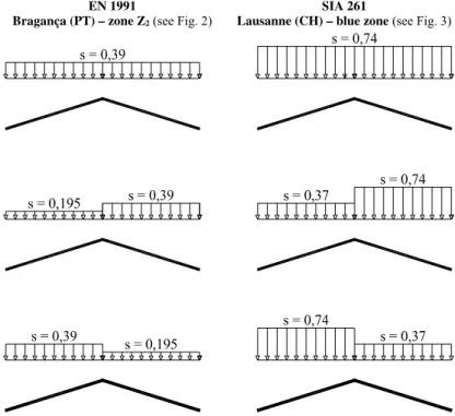
The roof shape factor is obtained analogously to EN 1991. SIA 261 standard only provides the snow load arrangements for three different types of roofs as it is shown in Fig. 4.
Fig. 3. Reference height for snow load at ground level [5]
Fig. 4.Arrangement of snow loads on roofs [5]
Design codes analysis and comparison
locations, taking the snow as leading variable action (exposure coefficient: normal topography Ce = 1,0; thermal coefficient: insulated roof Ct = 1,0; altitude h = 600 m; zone Z2 according to EN 1991;
h0 = 600 – 200 m according to SIA 261). The load arrangements for the undrifted case and the
drifted cases are determined using the guidance of both design codes and the shape profiles for the snow on roof are obtained as indicated in Fig. 5.
From the analysis of Fig. 5 one can verify that the SIA 261 design code recommends approximately twice the snow load on the roof relative to EN 1991, which indicates that the characteristic value of the snow load on ground imposed by the reference height h0 (see Fig. 3) is the determining factor explaining these results since the remaining parameters are identical to the EN 1991’ ones. This means that there is a greater concern with the action of snow in the Swiss code when compared with the European code requirements. Thus, current analysis is refined in order to understand this disparity.
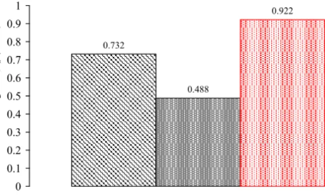
Fig. 6 points out that the characteristic value of snow load at ground level computed according to EN 1991 varies parabolically with the altitude for the three zones wherein the Portuguese territory is divided. As one can see in both the equation (8) and Fig. 6, the zone Z1 is the most subjected to snow action, where, for an altitude superior to 1350 m approximately, the value of snow load at ground level is greater than 2,5 kN/m2. Focusing in the SIA 261 standard, the current comparison becomes complex since the Helvetian code differentiates the Swiss territory by colours depending on the construction site location, as explained above. Aiming that current assessment becomes achievable, two localities were selected (Bragança in Portugal, and Lausanne in Switzerland) with the same approximate altitude of 600 m. Due to the fact that the city of Bragança integrates the EN 1991 zone Z2, and that this is not the most severe zone, the zone Z1 was also considered into this advanced analysis. Fig. 7 shows the characteristic values of the ground snow loads to be considered at the reference altitude of 600 m according to each design code.
From the analysis of Fig. 7, it can be concluded that, concerning EN 1991, there is an increased ground snow load on zone Z1 related to zone Z2 as it should be expected since the former zone comprises the Portuguese locations with the highest probability of large snow falls. Regarding the SIA 261 standard, which present an upper value compared to the EN 1991, result confirm that there is a higher incidence of the snow action despite similar locations were chosen.
EN 1991
Bragança (PT) – zone Z2 (see Fig. 2)
SIA 261
Lausanne (CH) – blue zone (see Fig. 3)
s = 0,195
s = 0,195
s = 0,37
0.0 0.5 1.0 1.5 2.0 2.5 3.0 3.5 4.0 4.5 5.0 5.5
0 200 400 600 800 1000 1200 1400 1600 1800 2000 Altitude, h (m)
S
now
lo
ad on t
h
e ground,
sk
(kN/m
2)
EN 1991 - Zone Z1 EN 1991 - Zone Z2 EN 1991 - Zone Z3
0.488
0.922
0.732
0 0.1 0.2 0.3 0.4 0.5 0.6 0.7 0.8 0.9 1
Sn
ow
lo
ad
on
the
gro
u
n
d
,
sk
(k
N/
m
2)
EN 1991 - Zone Z1 EN 1991 - Zone Z2 SIA 261
Fig. 6.Relation between characteristic ground snow load and altitude according to EN 1991
Fig. 7.Characteristic values of ground snow loads at 600 m altitude according to EN 1991
and SIA 261
Conclusions
Further to current investigation, following conclusions can be drawn:
No difference between European and Swiss design codes can be pointed out as regards neither permanent load values nor actions related’ partial safety factors;
Minor differences between EN 1990 and SIA 260 design codes regarding ULS load combinations were identified. As equivalent reliability level is compulsory regardless of material properties, SIA 261 design code compensates the fact that the accompanying variable actions are not multiplied by the appropriate partial safety factor using superior values for ψ0 factors when compared with those recommended by EN 1990;
Despite a common shape roof was examined, major result differences were observed, which may not exclusively be explained based on diverse countries’ climate realities;
The implementation of the use of European Norms will apparently aim to eliminate or to reduce the inconsistencies of snow load values in CEN Member States. In addition to that it appears quite clear that Swiss design codes procedure will have to be harmonized towards the CEN structural design suite of standards.
Bibliography
[1] CEN, 2009. Eurocode – Basis of structural design. (CEN) Brussels.
[2] CEN, 2009. Eurocode 1 – Actions on structures - Part 1-3: General actions – Snow loads. (CEN) Brussels.
[3] Ricardo Branco, 2013. Application of Eurocodes 0 and 1 – comparative analysis with SIA 260 and 261 Swiss design codes. MSc thesis, Polytechnic Institute of Bragança, Portugal, 112. [4] SIA, 2003. SIA 260 – Basis of structural design. Zurich: The Swiss Society of engineers and architects.
[5] SIA, 2003. SIA 261 – Actions on structures. Zurich: The Swiss Society of engineers and architects.
[6] H. Gulvanessian, J.A. Calgaro, M. Holický, 2002. Designers' guide to EN 1990: Eurocode: Basis of structural design. London: Thomas Telford.
[7] H. Gulvanessian, P. Formichi, J.A. Calgaro, 2008. Designers' guide to Eurocode 1: Actions on buildings EN 1991-1-1 and -1-3 to -1-7. London: Thomas Telford.
[8] ISO, 1998. ISO 4355: Bases for Design of Structures - Determination of Snow Loads on Roofs. Geneva.
[9] SIA, 2003. Bases pour l' élaboration des projets de structures porteuses: Actions sur les structures porteuses: Introduction aux normes SIA 260 et 261. Zurich: Truninger AG.

![Fig. 2.Distribution of C z factor in Portugal [2]](https://thumb-eu.123doks.com/thumbv2/123dok_br/16991180.763680/5.892.270.632.814.1071/fig-distribution-c-z-factor-portugal.webp)
![Table 3.Recommended values for C e coefficient for different topographies [2]](https://thumb-eu.123doks.com/thumbv2/123dok_br/16991180.763680/6.892.87.795.800.1048/table-recommended-values-c-e-coefficient-different-topographies.webp)