Patrícia Freitas Rodrigues
Mestre em Engenharia Metalúrgica
Structural Evolution of Ni
-
Ti Alloy Wires Produced
by Hot and Cold Rotary Forging
Dissertação para obtenção do Grau de Doutor em Ciência e Engenharia de Materiais
Orientador: Prof. Dr. Francisco Manuel Braz Fernandes, Professor Associado com Agregação
Faculdade de Ciências e Tecnologia Universidade Nova de Lisboa, Portugal
Co-orientador: Prof. Dr. Andersan dos Santos Paula, Professora Associada
Instituto Militar de Engenharia (IME), Brasil
Júri:
Presidente Prof. Doutor Paulo Manuel Assis Loureiro Limão Vieira Arguentes Prof. Doutora. Maria Teresa Freire Vieira
Prof. Doutor Manuel Fernando Gonçalves Vieira
Vogais Prof. Doutor Francisco Manuel Braz Fernandes Prof. Doutor Benoit Malard
Prof. Doutor Rui Jorge Cordeiro Silva
Patrícia Freitas Rodrigues
Mestre em Engenharia Metalúrgica
Structural Evolution of Ni
-
Ti Alloy Wires Produced by Hot
and Cold Rotary Forging
Dissertação para obtenção do Grau de Doutor em Ciência e Engenharia de Materiais
Orientador: Prof. Dr. Francisco Manuel Braz Fernandes, Professor Associado com Agregação
Faculdade de Ciências e Tecnologia Universidade Nova de Lisboa,
Co-orientador: Prof. Dr. Andersan dos Santos Paula, Professora Associada
Instituto Militar de Engenharia (IME), Brazil
Júri:
Presidente Prof. Doutor Paulo Manuel Assis Loureiro Limão Vieira Arguentes Prof. Doutora. Maria Teresa Freire Vieira
Prof. Doutor Manuel Fernando Gonçalves Vieira
Vogais Prof. Doutor Francisco Manuel Braz Fernandes Prof. Doutor Benoit Malard
Prof. Doutor Rui Jorge Cordeiro Silva
Structural Evolution of Ni-Ti Alloy Wires Produced by Hot
and Cold Rotary Forging
Copyright © Patrícia Freitas Rodrigues, Faculdade de Ciências e Tecnologia, Universidade Nova de Lisboa.
i
This thesis is dedicated
To my Parents, Antonio and Selma
and my brother Charles
Dedico este trabalho
aos meus pais, Antonio e Selma
iii
Acknowledgements
To God, for the gift of life, for the opportunity to begin and conclude one more step in my life, for every moment of learning and overcoming.
To the New University of Lisbon, through the Department of Materials Sciences, Faculty of Science and Technology, for the opportunity to participate in the doctoral program in materials science and engineering.
To Coordenação de Aperfeiçoamento de Pessoal de Nível Superior (CAPES-Brazil) through the federal program " Ciências Sem Fronteiras", for the grant scholarship. To CENIMAT and DCM, which through its employees and professors helped me many times.
To my Professor and Advisor Dr. Francisco Manuel Braz Fernandes for his attention, for his patience, for not letting me give up or discourage. For all the learning, exchange of knowledge, for countless discussions of the results. I thank you for all the academic opportunity that has provided me along these years. For helping me draw every step of this work, I am honored to have been your student.
To my Professor Dr. Andersan dos Santos Paula, for all dedication and friendship. For the unique opportunity to be completing this step with your collaboration. Throughout, conducting assays, conversations, discussions about results and content. I also thank you for all your personal and psychological support and for all the representativeness in my life.
To Professor Dr. Teresa Cidade coordinator of the doctoral program for all availability whenever I needed some guidance.
To the MIDAS project for the opportunity to break borders and be able to carry out a work with the various partnerships (Universidade Federal Fluminense, Instituto Militar de Engenharia, Universidade Politécnica de Timisoara, Universidade das Ilhas Baleares).
iv
To Professor Dr. Jorge Otubo and his team of the Aeronautical Technological Institute (ITA), Brazil for the material offered for studies.
To Rafaella Magalhães, by the partnership and discussion of results on orthodontics fields and the materials provided.
To the Morelli company for supplying the superelastic and thermo-activated orthodontic archwires.
To the GAC company for supplying the Bioforces orthodontic archwires used in this study.
To UNIDEMI in collaboration with Professor Dr. Telmo Santos and Parick Inacio to perform the localized heat treatment in the commercial superelastic orthodontic archwire Morelli.
To Dr. João Pedro Oliveira for all support, friendship and partnership. Thank you for each reading, results discussion and works conclusion.
To Professor Dr. Teresa Vieira, from the University of Coimbra, Portugal, I thank you for your suggestions as a member of the thesis Monitoring committee.
To Professor Dr. Rui Silva, from the New University of Lisbon, Portugal, I thank you for your support in measurements and providing materials and attention as a member of the thesis Monitoring committee.
To the laboratories of X-ray diffraction (synchrotron radiation): to Dr. Norbert Schell, Dr. Andreas Stark and Dr. Emad Maawad, for receiving us at the High Energy Materials Science Beamline P-07 from PETRA-III, Deutsches Electronen Synchrotron (DESY, Hamburg) and for their help during the experiments; and to the specialist Leonardo Wu for receiving us at the National Synchrotron Light Laboratory (LNLS, Campinas, SP, Brazil) and for his help during the experiments.
The team of beam time, Professor Francisco Manuel Braz Fernandes, João Pedro Oliveira, Professor Andersan dos Santos and Thiago Ferrão. Still to Edgar Camacho, for countless hours of rehearsal and then for support in developing scripts to facilitate our lives in representations and interpretations of results.
v
To Dr. Philippe De Parseval and Dr. Sophie Gouy from UMS 3623 - Centre de MicroCaractérisation Raimond Castaing for Electron Microprobe Analysis performed on some of the samples.
To Professor Dr Ritwik Basu from Indian Institute of Technology Bombay – India for EBSD tests performed in this work.
To the Military Institute of Engineering (IME Brazil) that through the team: Rodolfo, Saulo, Mônica, Andrey, Naiara, Thiago, conducted tests in the SEM and also exchange of knowledge and other activities developed.
To Dr. Shimeni Ribeiro for all these years of coexistence, works developed and EBSD tests performed in Universidade Federal Fluminense.
To the company Villares Metals, for conducting the chemical analysis of the starting materials of this work.
Last but not least, the people of my life...
To my parents Antônio Barizon, Selma Freitas, my brother Charles Barizon who during my life have always stood beside me to support me, not letting me give up and encouraging me to always dream, reaching out to me always. Our union makes a difference. My sister-in-law Andrea and our Princess Maria Antonia for every moment overcome, every smile and word that are fundamental to our happiness, together we are invincible.
To Miguel for being my base, for always being by my side, for smiling with me, for being happy in every victory, for wiping my tears, for sharing joys and frustrations, for encouraging me, for rooting for my success, for teaching me every day, for looking at me beyond of the eyes... for being simply you... You're my person!
To my relatives, uncles and cousins in which each, in his own way, contributed to that in this stage of my life.
vi
To Andreia Lopes, in particular for being with me since the beginning. For sharing happy and less happy moments. For sharing with me words and thoughts, you have been very important in these years. I will take you to my life!
To the friends Portugal presented me: Alessandra and Manu for the coexistence and enormous help over these years.
To my friends of all time, present in several stages of my life, Ana Paula, Danusa, Júnior, Flávia, Gabriele, Itamara, Mariama, Millene, Nathália, Polliana, Eduardo, Lidiane, Victor, Carla, Tiago, Thaís. You are part of one more chapter of my life.
To the friends that visited me and shared a little more closely this moment: Ana Paula, Luís Fernando, Eduardo, Cristiane, Thaís, Nathália, Ricardo, Adriana, Vanessa, Leilson. Your presence was very important.
To Carol who has been a part of my life for many years, even far away, she has managed to be present at all times. My dear friend an ocean away is nothing. Thank you for always being my companion.
To Victor Lauriano for being important in my life, more than a friend from the beginning of this walk to life. Always supporting me at all professional and personal moments, smiling or crying... he's always been there for me.
To all who have in some way contributed to the realization of this work and who I have not mentioned here.
vii
Agradecimentos
À Deus, pelo dom da vida, pela oportunidade de iniciar e concluir mais uma etapa em minha vida, por cada momento de aprendizagem e superação.
À Universidade Nova de Lisboa, por meio do Departamento de Ciências de Materiais da Faculdade de Ciências e Tecnologia, pela oportunidade de participação no Programa Doutoral em Ciências e Engenharia de Materiais.
Ao Coordenação de Aperfeiçoamento de Pessoal de Nível Superior (CAPES - Brasil)
por meio do programa Federal “Ciências sem Fronteiras”, pela concessão da bolsa de
estudos.
Ao CENIMAT, que através de seus funcionários e professores fizeram parte dessa caminhada com seus trabalhos desenvolvidos, ensinamentos e dedicação.
Ao meu professor orientador Doutor Francisco Manuel Braz Fernandes por sua atenção, por sua imensa paciência, por não me deixar desistir e desanimar. Por toda aprendizagem, troca de conhecimentos e por inúmeras discussões dos resultados. Agradeço ainda por toda oportunidade académica que me proporcionou ao longo destes anos. Por me ajudar a desenhar cada passo deste trabalho, sinto-me honrada em ter sido seu orientada.
À minha professora orientadora Doutora Andersan dos Santos Paula, por todos esses anos de convivência dedicação e amizade. Pela oportunidade única de estar concluindo mais esta etapa com sua participação. Por todo ensinamento, realização de ensaios, conversas, debates sobre resultados e conteúdo. Agradeço ainda por todo apoio pessoal e psicológico e ainda por toda a representatividade em minha vida.
À Professora Doutora Teresa Cidade Coordenadora do Programa Doutoral por toda disponibilidade sempre que precisava de alguma orientação.
viii
Ao Doutor Jorge Otubo e sua equipe do Instituto Tecnológica da Aeronáutica (ITA), Brasil pelo materialcedido para estudos.
À Rafaella Magalhães, pela parceria e imensas discussões de resultados sobre ortodontia e pelos materiais fornecidos.
À empresa Morelli pelo fornecimento dos fios superelásticos e termo-ativados. À empresa GAC pelo fornecimento dos fios BioForces usados neste trabalho.
Ao UNIDEMI em colaboração com Professor Doutor Telmo Santos e ao Doutorando Parick Inacio realizaram o tratamento térmico localizado no fio superelástico comercial Morelli.
Ao colega Doutor João Pedro Oliveira por todo apoio, amizade e parceria. Obrigada por cada leitura, discussão de resultados e conclusões de trabalhos.
À Professora Doutora Teresa Vieira, da Universidade de Coimbra, Portugal, agradeço as suas sugestões enquanto membro da comissão de acompanhamento da tese.
Ao Professor Doutor Rui Silva, da Universidade Nova de Lisboa, Portugal, agradeço ao seu apoio em ensaios e disponibilização de materiais e atenção enquanto membro da comissão de acompanhamento da tese.
Aos laboratórios de diffração de raios-X (radiação de sincrotrão): ao Dr. Norbert Schell, Dr. Andreas Stark e Dr. Emad Maawad, por nos receber no Deutsche Electron Synchrotron (DESY) e pela sua ajuda durante as experiências; e ao Especialista Leonardo Wu por nos receber no Laboratório Nacional de Luz de Sincrotrão (LNLS) e pela sua ajuda durante as experiências.
Os companheiros de tempo de feixe, Professor Doutor Francisco Manuel Braz Fernandes, ao Doutor João Pedro Oliveira, Doutora Andersan dos Santos e Mestre Thiago Ferrão. Ainda ao Mestre Edgar Camacho, pelas inúmeras horas de ensaio e depois pelo apoio ao desenvolver scripts para facilitar nossa vida em representações e interpretações dos resultados.
ix
Ao Doutor Philippe De Parseval e a Doutora Sophie Gouy do UMS 3623 - Centre de MicroCaractérisation Raimond Castaing for Electron Microprobe Analysis pela realização das análises de micorssonda em algumas amostras do trabalho.
Indian Institute of Technology Bombay – India; em colaboração com o Professor Doutor Ritwik Basu pela realização das análises de EBSD.
Ao Instituto Militar de Engenharia (IME Brazil) que através da equipe: Rodolfo, Saulo, Mônica, Andrey, Naiara, Thiago, realizaram ensaios no MEV e ainda troca de conhecimentos e outras atividades desenvolvidas.
À Doutora Shimeni Ribeiro por todos esses anos de convivência, trabalhos desenvolvidos e análise de EBSD realizadas na Universidade Federal Fluminense. À empresa Villares Metals, pela realização da análise química dos materiais de partida deste trabalho.
E por último, mas não menos importante, as pessoas de minha vida…
Aos meus pais Antônio Barizon, Selma Freitas, meu irmão Charles Barizon que no decorrer de minha vida sempre estiveram ao meu lado para me apoiar, não me deixar desistir e me estimulou a sonhar sempre me estendendo a mão em todos os momentos. A nossa união faz diferença. A minha cunhada Andrea e nossa princesa Maria Antonia porcada momento superado, cada sorriso e palavra que são fundamentais para nossa felicidade, juntos somos imbatíveis.
Ao Miguel por ser minha base, por estar ao meu lado sempre, por sorrir comigo, por ficar feliz em cada vitória, por enxugar minhas lágrimas, por dividir alegrias e frustrações , por me incentivar, por torcer pelo meu sucesso , por me ensinar todos os dias, por me olhar além dos olhos… por ser simplesmente você… Você é a minha
pessoa!
Aos meus familiares, tios e primos em que cada um, à sua maneira, contribuiu para que nesta etapa de minha vida.
x
À Andreia Lopes, em especial, por estar comigo desde o início. Por dividir momentos felizes e menos felizes. Por dividir comigo palavras e pensamentos, você foi muito importante nestes anos. Vou te levar para vida!
Às minhas amigas que Portugal que presenteou: Alessandra e Manu pela convivência e pela enorme ajuda ao longo desses anos.
Aos meus amigos de sempre, presentes em diversas etapas de minha vida, Ana Paula, Danusa, Júnior, Flávia, Gabriele, Itamara, Mariama, Millene, Nathália, Polliana, Eduardo, Lidiane, Victor, Carla, Tiago, Thaís. Vocês fazem parte de mais um capítulo da minha vida.
Aos amigos que Deus proporcionou me visitar e dividir um pouco mais de perto este momento: Ana Paula, Cristiane, Luís Fernando, Eduardo, Thaís, Nathália, Ricardo, Adriana, Vanessa, Leilson. A presença de vocês foi muito importante.
À Carol que faz parte de minha vida a muitos anos, mesmo longe conseguiu ser presente em todos os momentos. Minha amiga querida um oceano de distância não é nada. Obrigada por ser sempre minha companheira.
Ao Victor Lauriano por ser importante na minha vida, mais que um amigo desde o início desta caminhada para vida. Sempre me apoiando em todos os momentos
profissionais e pessoais, sorrindo ou chorando … ele sempre esteve ao meu lado.
A todos que de alguma forma contribuíram para a realização deste trabalho e que aqui não tenha mencionado.
I
Abstract
Ni-Ti shape memory alloys (SMA), have interesting functional properties such as shape memory effect and superelasticity that enable their use in different segments. These functional characteristics are obtained through the thermomechanical processing (hot and cold). The hot deformation may promote the intended metallurgical transformations and the microstructural changes are improved by final cold deformation. These processes influence the final mechanical properties of the materials and, by consequence, their applications. This work focused on a rich Ni-Ti alloy, which may be used in the orthodontic archwires since the alloys used for this purpose need to show superelastic characteristics at room and oral temperature. It is sought by the mechanical and thermal treatments that the material displays an austenite finish temperature below room temperature.
In this work, the characteristics of the thermomechanical processing are studied using samples representative of the different processing steps. For each processing step, the effect of the process parameters on the phase transformation temperature, superelasticity and shape memory effects was assessed and correlated to its microstructure. The structural analysis of each sample was performed by different techniques, which allowed the identification of the thermomechanical processing evolution. It was noticed that the austenite finish temperature was close to room temperature for all the steps. For all the samples, an austenite matrix at room temperature was observed. Different heat treatments were applied to identify the most suitable changes to be proposed along the rotary forging steps. Thermomechanical treatments were performed to understand and verify the structural evolution (by X-ray diffraction, using synchrotron radiation) and the mechanical behavior during the hot and cold deformations. These treatments allowed us to observe and discuss restoration phenomena, such as dynamic recovery and recrystallization.
In addition, orthodontic archwires were studied in a reverse engineering approach to identify their structural characteristics and the corresponding functional behavior. The characterization of commercial functionally graded NiTi orthodontic archwire was performed and the introduction of graded functionality in conventional archwires was analyzed.
This study aimed to contribute to the development of processing strategies that will give rise to more consistently uniform characteristics of Ni-Ti shape memory alloys and a minimization of the failures occurring during processing.
III
Resumo
As ligas de Ni-Ti com memória de forma, possuem propriedades funcionais bem distintas, tais como memória de forma e superelasticidade, que viabilizam o seu uso em diversos segmentos. Essas características são obtidas a partir dos processamentos termomecânicos, a quente ou a frio, aplicados ao material. A deformação a quente promove as transformações metalúrgicas pretendidas e a microestrutura é modificada pelas deformações a frio subsequentes. Esses processamentos influenciam o comportamento mecânico e as propriedades finais e, por conseguinte, a sua aplicação final.
Este trabalho teve como foco o estudo de uma liga Ni-Ti rica em níquel, que pode ser usada para produção de fios ortodônticos e que apresente para tal comportamento superelástico próximo da temperatura ambiente e temperatura oral. Esse comportamento é obtido através de tratamentos mecânicos e térmicos aplicados. Neste trabalho são estudadas as características do processamento termomecânico, através de cada uma das amostras representativas das diferentes etapas de processamento. Para as amostras das diferentes etapas de processamento, o efeito dos parâmetros de processo na temperatura da transformação de fase, os efeitos de memória de forma e superelasticidade foram avaliados e correlacionados com a sua microestrutura. A análise estrutural de cada amostra foi realizada por diferentes técnicas que permitiram a observação da evolução do processamento termomecânico. Obteve-se, para todos os passos de processamento estudados, uma temperatura de final de transformação em austenite próxima da temperatura ambiente. O material com uma matriz austenítica à temperatura ambiente foi observado para todas as amostras. Foram realizados tratamentos térmicos para identificar as alterações a propor nos tratamentos ao longo do forjagem rotativa. Foram realizados tratamentos termomecânicos para entender e verificar a evolução estrutural (por difração de raios-X usando radiação de sincrotrão) e o comportamento mecânico durante as deformações a quente e a frio. Estes tratamentos permitem observar e discutir fenómenos de recuperação e de recristalização dinâmicas.
Além disso, os arcos ortodônticos foram usados em uma abordagem de engenharia reversa para identificar a sua estrutura e as correspondentes características funcionais. Foi realizada a caracterização de arames ortodônticos comerciais e foi analisada a introdução de gradiente funcional em arcos convencionais.
Este estudo teve como objetivo contribuir para o desenvolvimento de estratégias de processamento que darão origem a características mais consistentemente uniformes das ligas com memória de forma e a uma minimização das falhas ocorridas durante o processamento.
V
Contents
1. INTRODUCTION ... 1
1.1. Structure of the Study ... 2
2. STATE OF THE ART ... 5
2.1. Ni-Ti Shape Memory Alloys ... 5
Phase Diagram and Crystal Structures ... 6
2.1.1. Shape Memory Effect and Superelasticity ... 7
2.1.2. Precipitation Phenomena ... 12
2.1.3. 2.2. Processing ... 16
Casting Process ... 17
2.2.1. Heat Solution Treatment Before Thermomechanical Process ... 18
2.2.2. Thermomechanical Process ... 20
2.2.3. Hot Working ... 20
2.2.3.1. Cold Working ... 26
2.2.3.2. Heat Treatments... 26
2.2.4. Functional Gradient ... 28
2.2.5. 2.3. Textural Evolution ... 31
2.4. Orthodontic Archwires ... 34
3. MATERIALS AND METHODS ... 39
3.1. Ni-Ti Alloys ... 40
As-cast and Remelted alloys ... 40
3.1.1. Thermomechanical Process ... 41
3.1.2. Heat Treatments... 44
3.1.3. 3.2. Orthodontic Archwires ... 45
Localized Heat Treatment Performed in Superelastic Orthodontic Archwire (Morelli SE) ... 45
3.2.1. 3.3. Characterization Techniques ... 46
Scanning electronic microscopy (SEM) ... 46
VI
Electron Microprobe Analysis (EMPA) ... 47 3.3.3.
Optical microscopy (OM) ... 47 3.3.4.
X-Ray Diffraction Analysis (XRD) ... 47 3.3.5.
Conventional X-Ray Source (XRD) ... 48 3.3.5.1.
Synchrotron Radiation X-ray Diffraction (SR-XRD) ... 49 3.3.5.2.
Petra III – P07/DESY ... 49 3.3.5.3.
LNLS - XRD 1 / CNPEM... 53 3.3.5.4.
Differential Scanning Calorimetry (DSC) ... 54 3.3.6.
Thermomechanical Analysis (TMA) ... 55 3.3.7.
Dilatometric Analysis ... 55 3.3.7.1.
Three-point Bending Tests ... 56 3.3.7.2.
Mechanical testing ... 56 3.3.8.
Three-point bending tests ... 56 3.3.8.1.
4. RESULTS AND DISCUSSION ... 59
4.1. Starting Materials (as-cast and remelting condition) ... 60 Microstructural Characterizations of the alloys 1, 2 and 3 (first hot deformation and second 4.1.1.
cold deformation samples) ... 64 NiTi_1_Rem Alloy 1 As Remelted ... 66 4.1.2.
Starting Materials Summary ... 68 4.1.3.
4.2. Initial Thermomechanical Process (Rotary Forging Steps) ... 69 Hot Rotary Forging Steps ... 69 4.2.1.
First Hot Rotary Forging Step ... 69 4.2.1.1.
Third Hot Rotary Forging Step ... 73 4.2.1.2.
Cold Rotary Forging Steps ... 76 4.2.2.
First Cold Rotary Forging Step ... 76 4.2.2.1.
Second Cold Rotary Forging Step ... 79 4.2.2.2.
Rotary Forging Process Evolution ... 81 4.2.3.
Microstructural and Compositional Evolution by Thermal and Chemical Analysis ... 82 4.2.3.1.
Microstructural Evolution by Optical Microscopy ... 85 4.2.3.2.
Microstructural Evolution by EBSD ... 87 4.2.3.3.
Microstructural Evolution by SEM ... 91 4.2.3.4.
Textural Evolution ... 93 4.2.3.5.
Rotary Forging Process Evolution Summary ... 95 4.2.4.
VII
Solution Heat Treatment between deformations steps ... 98 4.3.2.
First Hot Forging Sample (NiTi_1_1F_1h) ... 98 4.3.2.1.
First Hot Forging Sample (NiTi_1_1F_1h) and First Hot Forging Sample (NiTi_1_1F_1h) 4.3.2.2.
heat treated at 800 ºC during 10 minutes. ... 100 Comparison of the First Hot Forging Sample heat treated at 800 ºC during 10 minutes 4.3.2.3.
and First Hot Forging Sample heat treated at 800, 850, 900 and 950 ºC during 120 minutes ... 101 Intermediate Heat Treatment (850 ºC during 15 minutes) ... 108 4.3.3.
Aging Treatment ... 110 4.3.4.
Thermomechanical Process Proposed (Rotary Forging Route) ... 113 4.3.5.
4.4. Thermomechanical Process Simulation ... 114 Optimization of Hot and Cold Working Parameters Using Synchrotron Radiation ... 114 4.4.1.
Optimization of Hot Deformations with Different Strain Rate ... 124 4.4.2.
Aging Treatment Optimization ... 128 4.4.3.
Thermomechanical Process Simulation Summary ... 131 4.4.4.
4.5. Orthodontic Archwires ... 132 Superelastic orthodontic archwire ... 133 4.5.1.
Thermo-active orthodontic archwire ... 135 4.5.2.
Ni-Ti orthodontic archwires with graded actuating forces ... 136 4.5.3.
Commercial Ni-Ti Orthodontic Archwires Summary ... 143 4.5.4.
Functionally Graded Orthodontic Archwires ... 143 4.5.5.
5. CONCLUSIONS AND FUTURE WORK ... 153
5.1. As-cast and remelt ... 153 5.2. Hot Forging Steps ... 153 5.3. Cold Forging Steps ... 154 5.4. Aging Heat Treatment ... 154 5.5. Orthodontic Archwires Characteristics ... 154 5.6. Future Work ... 155
6. REFERENCES ... 157
IX
List of Figures
Figure 2.1 - Phase diagram of Ti-Ni alloy with the phase equilibrium between the B2 and Ni4Ti3 phases
added. (Otsuka, 2002) ... 6
Figure 2.2 - Scheme of transformation of (a) cubic (B2) austenite to (b) monoclinic (B19’) phase.
(Miyazaki, 2009) ... 7
Figure 2.3 - (a), (b) and (c) Schematic illustration of the mechanism of the shape-memory effect and
superelasticity. (Otsuka, 2002) ... 8
Figure 2.4 - Typical superelastic behavior diagram of a shape memory alloy. (Chowdhury, 2017) ... 9
Figure 2.5 - Stress-temperature diagram for shape memory alloy. (Otsuka, 2005) ... 10
Figure 2.6 - Schematic drawing of stress-induced phase transformations as observed in a uniaxial tensile
loading/unloading experiment with two-step transformations. Stress is plotted as a function of strain.
(Olbricht, 2011) (b) stress x strain curves (compression and tension behavior). [adapted from (Sittner,
2005)] ... 12
Figure 2.7 - TTT diagram describing aging behavior for Ti-52 at%Ni. (Nishida, 1986) ... 13
Figure 2.8 - TTT (time-temperature-transformation) for the effect of shorter ageing temperature and
time on the transformation temperature of Ti-50.8% Nitinol wire with a starting Af temperature of 11 ºC.
(Pelton, 2000) ... 13
Figure 2.9 - A unified model for explaining the microstructure evolution at low Ni supersaturation (a and
b) and high Ni supersaturation (c and d). It also explains both three-stage and two-stage transformation
behavior of supersaturated Ti–Ni solid solution. (Fan, 2004) ... 15
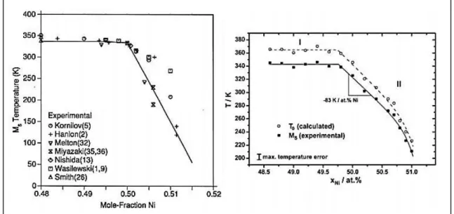
Figure 2.10 - Dependence of Ms Temperature on Ni composition of Ni-Ti alloys, left Tang et al. (Tang,
1997), right Frenzel et al. (Frenzel, 2010) ... 16
Figure 2.11 - Schematic view of NiTi manufacturing process. [adapted from (Nakahata, 2011)] ... 17
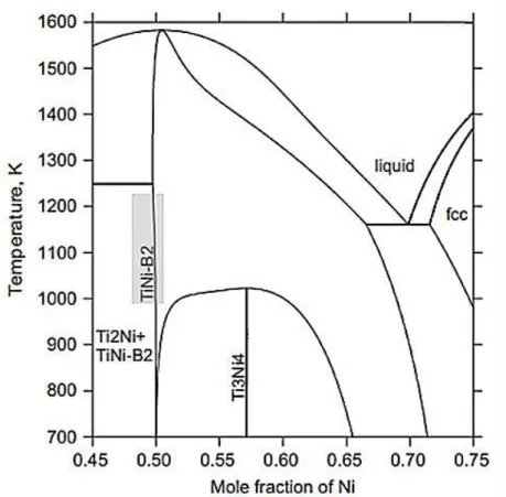
Figure 2.12 - Metastable phase diagram of the Ti–Ni system with the Ni content rang studied.
[adapted from (Povoden-Karadeniz, 2013)] ... 19
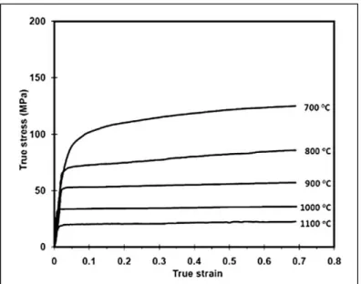
Figure 2.13 – Ni-Ti SMA true stress-true strain curves at different temperatures and strain rate 0.001 s-1. (Morakabati, 2011) ... 23
Figure 2.14 - Optical microstructures of Ni-Ti samples at 800 ºC – (a) 0.001 s-1; (b) 0.01 s-1; (c) 0.1 s-1 and (d) 1 s-1. [adapted from (Jiang, 2013a)] ... 23 Figure 2.15 - Microstructural evolution of Ni-Ti alloy with increasing strain, deformed in compression at
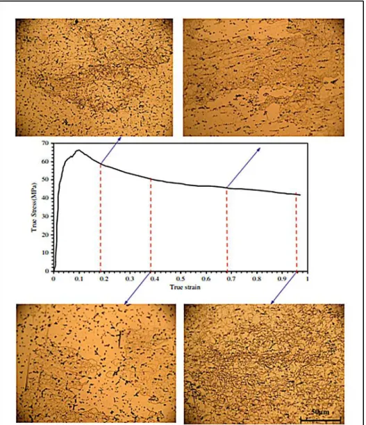
temperature of 1050 ºC and a strain rate of 0.1 s-1. (Khamei, 2010) ... 24 Figure 2.16 - Work hardening rate analyses. It should be noted that third order polynomials were fitted
to the θ–σ curves (until the peak point corresponding to θ= 0) to get smoother -dθ/dσ–σ curves.
(Mirzadeh, 2014) ... 25
Figure 2.17 - DSC charts of the samples after solution treatment at 800 ºC/15 min and aged at 400, 450,
X
Figure 2.18 - Designs of microstructural or compositional functionally graded (FG) Ni-Ti. (a) and (b) show
examples of functionally graded in series and parallel configuration (d). (e) and (f) show examples of the
series configuration mechanical behavior and parallel configuration mechanical behavior. [adapted from
(Shariat, 2017)] ... 29
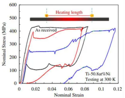
Figure 2.19 - Tensile deformation behavior of Ti-50.8 at.%Ni wires after local over-aging by electrical
resistance heating. (higher plateau – no heat-treated section and lower plateau – treated section).
(adapted from (Shariat, 2017))... 30
Figure 2.20 - The ϕ2 sections of the complete orientation distribution function (ODF) of (a) starting
material and (b) 60 %, (c) 80% and (d) 90% deformed Ni-Ti. (Suresh, 2012) ... 32
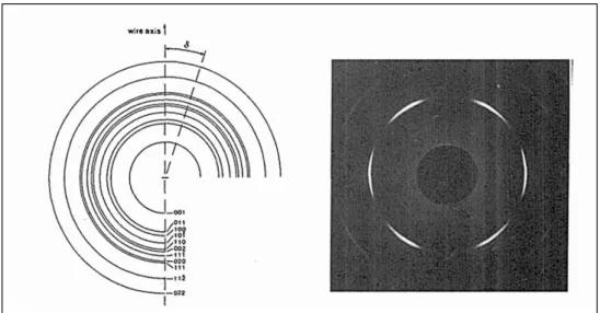
Figure 2.21 - Observed reflection on wire axis and diffraction pattern of the B2 phase. (Willemse, 1991)33
Figure 2.22 - Pole Figures (110)B2 obtained from as-received, heat treated at 500 ºC and deformed. (Paula., 2007) ... 33
Figure 2.23 - Sequence of the orthodontic treatment. (Files
provided by Dr. Raffaela Magalhães with patient authorization) ... 34
Figure 2.24 - Load-deflection curves of the wires with graded actuating forces at different temperature
and the superelastic actuation is identified. ... 35
Figure 3.1 – Vacuum Arc Remelting (VAR) a) During remelting process; b) After remelting process; and c)
three processed ingots... 41
Figure 3.2 – Scheme of the initial thermomechanical processing applied to the ingots, with forging
stages, temperature and time of the intercalated heat treatments and sample diameters. ... 42
Figure 3.3 - Equipment: a) 4 hammers and b) 2 hammers, used to rotary forging steps ... 42
Figure 3.4 - Scheme for the samples identification... 44
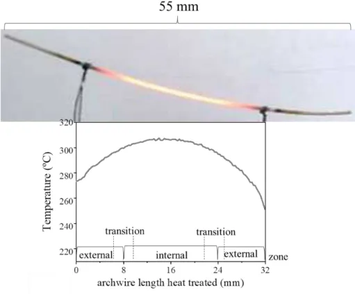
Figure 3.5 - Schematic view of the electrical local heating system of Ni-Ti wire and temperature profile.
(Unpublished data from Inácio and Santos) ... 46
Figure 3.6 - Schematic representation of the Bragg’s law. ... 48
Figure 3.7 - Examples of XRD results (1F1q sample), at high/low temperature: during heating and
cooling, between −120 and 120 °C (a); Pole Figures (b) (Rodrigues, 2017a) ... 49
Figure 3.8 - Scheme of the SR-XRD measurement at room temperature along the sample diameter. ... 50
Figure 3.9 - Schematic representation of the SR-XRD measurement at room temperature along gauge
length (32 mm), total length of the localized heat treatment. Phi 0 and phi 90 to the normal direction.
(more details in the text) ... 51
Figure 3.10 - Scheme of the direction of the beam, part of the interior of the equipment and the position
of the detector in relation to the sample. ... 52
Figure 3.11 - Scheme of the thermomechanical process with in-situ deformation experiments
(thermomechanical cycles performed in DESY) ... 53
Figure 3.12 - Thermo-mechanical simulator, the Gleeble® Synchrotron system and scheme of the
XI
Figure 3.13 - Scheme of the thermomechanical process applied with strain rate of 10-3 s-1 (hot
deformations performed in LNLS). ... 54
Figure 3.14 - Differential scanning calorimetry schemes. ... 55
Figure 3.15 - Displacements (0.5, 0.75 and 1.0 mm) analyzed in deflection curve (slope of the
deactivation curve - superelastic behavior). ... 57
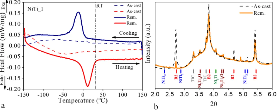
Figure 4.1 - (a) DSC curves NiTi_1_as-cast and remelted samples (b) SR - XRD - NiTi_1_as-cast and
remelted samples ... 60
Figure 4.2 - (a) DSC curves NiTi_2_as-cast and remelted samples (b) SR - XRD - NiTi_2_as-cast and
remelted samples ... 61
Figure 4.3 - (a) DSC curves NiTi_3_as-cast and remelted samples (b) SR - XRD - NiTi_3_as-cast and
remelted samples ... 62
Figure 4.4 – DSC results: (a) heating up to 500 ºC, (b) Af temperature (remelted condition, after solution
heat treatment at 950 ºC during 2 h and after heating up to 500 ºC. ... 63
Figure 4.5 - (a) DSC curves (b) SR-XRD diffractograms of the 1, 2 and 3 alloys at first hot deformation step
(1F_1h) and at first cold deformation step (6F_4h2c). ... 65
Figure 4.6 - SEM images of NiTi_1_rem: (a) Secondary electron image, (b) Backscattered image ... 67
Figure 4.7 – (a) EDS results of the NiTi_1_Rem sample, (b) Micrograph of the NiTi_1_rem. (c and b) EBSD
map of NiTi_1_rem sample at room temperature. ... 68
Figure 4.8 – (a) DSC curves NiTi_1_1F_1h sample (b) SR - XRD of NiTi_1_1F_1h sample. ... 70
Figure 4.9 - XRD results at high/low temperature: (a)during heating and cooling, between -120 and
120 ºC (b) separate diffractograms for three different temperatures
(-120, 25 and 120 ºC) ... 71
Figure 4.10 – (a) Heat release by continuous heating of the NiTi alloy to different maximum
temperatures. (b) DSC curves: NiTi_1_1F1h (N-HTT = NiTi_1_1F1h without heat treatment) and
NiTi_1_1F_1h heat treated from 250 to 450 ºC. ... 72
Figure 4.11 – Recovery recrystallization results: (a) DSC curves heat treated to 500 ºC; (b) XRD at high
temperature and (c) FWHM and d-spacing observed. ... 73
Figure 4.12 - (a) DSC curves NiTi_1_3F_3h sample (b) SR - XRD of NiTi_1_3F_3h sample. ... 74
Figure 4.13 - NiTi_1_3F_3h XRD results at high/low temperature: (a) during heating and cooling,
between -120 and 120 ºC (b) separate diffractograms for three different temperatures
(-120, 25 and 120 ºC) ... 75
Figure 4.14 – NiTi_1_3F_3h - Recovery recrystallization results: (a) DSC curves heat treated to 500 ºC; (b)
XRD at high temperature and (c) FWHM and d-spacing observed. ... 76
Figure 4.15 – (a) DSC curves NiTi_1_5F_4h1c sample (b) SR - XRD of NiTi_1_5F_4h1c sample. ... 77
Figure 4.16 – NiTi_1_5F_4h1c XRD results at high/low temperature: (a)during heating and cooling,
between -120 and 120 ºC (b) separate diffractograms for three different temperatures
XII
Figure 4.17 – NiTi_1_5F_4h1c - Recovery recrystallization results: (a) DSC curves heat treated to 500
ºC; (b) DSC thermal characterization from -150 to 150 ºC before and after heat treatment to 500 ºC
compared (1- before heat treatment -dash line and 2- after heat treatment – solid line). ... 78
Figure 4.18 – (a) DSC curves NiTi_1_6F_4h2c sample (b) SR - XRD of NiTi_1_6F_4h2c sample. ... 79
Figure 4.19 – NiTi_1_6F_4h2c XRD results at high/low temperature: (a)during heating and cooling,
between -120 and 120 ºC (b) separate diffractograms for three different temperatures
(-120, 25 and 120 ºC). ... 80
Figure 4.20 – NiTi_1_6F_4h2c - Recovery recrystallization results: (a) DSC curves heat treated to 500
ºC; (b) DSC thermal characterization from -150 to 150 ºC before and after heat treatment to 500 ºC
compared (1- before heat treatment -dash line and 2- after heat treatment – blue line). ... 81
Figure 4.21 – DSC curves of the Rem., 1F1h,3F3h, 5F_4h1c and 6F_4h2c steps, cooling curves and heating
curves. ... 82
Figure 4.22 – Chemical analysis (EMPA) results (a) elements at.%; (b) Comparison between at.%Ni x Af;
(c) elements at.% global composition values, in addition Ni effective after Ti2Ni4O and TiC observation.. 84
Figure 4.23 – Micrographs of the NiTi_1 alloy hot and cold deformations steps. ... 86
Figure 4.24 - Enlarged image quality maps of the NiTi_1 alloy hot and cold deformations steps. ... 88
Figure 4.25 - Enlarged image quality maps of NiTi_1_1F_1h sample ... 90
Figure 4.26 - Enlarged image quality maps of NiTi_1_3F_3h sample ... 90
Figure 4.27 - SEM images of the NiTi_1 alloy hot and cold deformations steps (backscatter mode). ... 92
Figure 4.28 - Variation of the 2θ peak position and intensity of the (110)B2 (200)B2 (211)B2 peaks along the
azimuthal angle (transmission mode) and Pole Figure (110)B2 (reflection mode) of the NiTi_1 alloy hot
and cold deformations steps. ... 94
Figure 4.29 - a) comparison between DSC curves (a) and superposition of the SR-XRD patterns (b) of
NiTi_1_Rem sample and NiTi_1_Rem heat-treated at 800 ºC during 30 minutes and 950 ºC during 120
minutes. ... 97
Figure 4.30 – Scheme of locations of the SR-XRD measurements on the samples and First structural
characterization: A) Outer Spot - Debye–Scherrer rings, B) Inner Spot - Debye–Scherrer rings of first hot
forging step (NiTi_1_1F_1h). ... 99
Figure 4.31 – DSC curves of the First Hot Forging Sample (NiTi_1_1F_1h)– Spot A (outer) and Spot B
(inner) ... 100
Figure 4.32 – a) comparison between SR-XRD pattern of First Hot Forging Sample (NiTi_1_1F_1h) and
First Hot Forging Sample (NiTi_1_1F_1h) heat-treated at 800 ºC during 10 minutes c) DSC curves. ... 101
Figure 4.33 – a) DSC curves on cooling from the B2 regime and DSC curves on heating from the B19’. The
five DSC curves show the influence of solution heat treatment. b) Peak temperatures - Mp cooling and Ap
heating. ... 103
Figure 4.34 - Debye–Scherrer diffraction rings at the outer (A) and inner (B) of the mapped area
presented in Figure 3 for each sample (800 ºC/10 min, 800 ºC/120 min, 850 ºC/120 min, 900 ºC/120 min
XIII
Figure 4.35 – a) outer (A) b) (B) inner – Sequence of XRD line diagrams at different solution heat
treatment obtained by the integration of the diffraction patterns recorded at room temperature. ... 105
Figure 4.36 – Cartesian and 3d plots transform of Debye–Scherrer diffraction rings (azimuthal angles) vs.
2θ for A and B spots for each heat-treated sample. ... 106
Figure 4.37 - Microstructure of the specimens submitted to solution heat treatment. ... 107
Figure 4.38 - Partial phase diagram of Ti-Ni system. (adapted from (Somsen, 1999)) ... 109
Figure 4.39 - DSC Curves of aging temperatures at 30 minutes soaking time: 350 ºC, 400 ºC and 450 ºC.
... 112
Figure 4.40 – Rotary forging route proposed with forging stages, temperature and time of the
intercalated heat treatments and sample diameters. ... 113
Figure 4.41 - Thermomechanical treatment simulation scheme applied with highlighted of the heating,
deformations and aging treatment steps. ... 115
Figure 4.42 - SR - XRD patterns obtained during heating up to 850 ºC and d-spacing evolution. ... 116
Figure 4.43 – Hot (1, 2, 3 and 4) and cold (5 and 6) true stress-true strain curves and work hardening rate
analysis (2nd, 3rd and 4th deformations). ... 116 Figure 4.44 - FWHM, d-spacing and SR-XRD patterns of the hot and cold deformations during
thermomechanical measurement with a strain rate of 10-3 s-1. ... 118 Figure 4.45 - 3D plots transform of Debye–Scherrer diffraction rings (azimuthal angles) vs. 2θ –
before, peak and after each deformation (hot and cold). ... 120
Figure 4.46 - Hot and cold deformations behavior and crystallographic orientation... 121
Figure 4.47 - SR-XRD patterns after hot deformations (b) and after cold deformations (c). ... 121
Figure 4.48 – Superposition of SR-XRD patterns of each minute during aging treatment at 500 ºC during
30 minutes. ... 123
Figure 4.49 - DSC curves of the initial (NiTi_1_rem. Heat treated at 950 ºC/120 min.) and final (after
thermomechanical simulation) samples. ... 124
Figure 4.50 – Superposition of the SR-XRD patterns obtained during cooling after aging treatment at 500
ºC during 30 min. ... 124
Figure 4.51 – NiTi_1_Rem. true stress-true strain curves of the hot deformations (at 850 ºC) evolutions
with strain rate of 10-1s-1and comparison between the FWHM and 2θ evolution. ... 126 Figure 4.52 - DSC curves of the NiTi_1_Rem heat treated at 950 ºC during 120 min and after hot
deformations with strain rate of 10-1s-1. ... 127 Figure 4.53 – Superposition of the SR-XRD patterns (0, 10, 20 and 30 minutes) during stress-assisted
aging treatment at 500 ºC during 30 min under 70 MPa. ... 129
Figure 4.54 - Superposition diffractograms of the stress-free and stress-assisted aging treatment at 500
ºC during 30 minutes. ... 130
Figure 4.55 – DSC curves of the NiTi_1_Rem sample after stress-free and stress-assisted aging. ... 131
Figure 4.56 -DSC curves of the superelastic orthodontic archwire ... 134
XIV
Figure 4.58 - DSC curves, dilatometry measurement curve and SR-XRD patterns at room temperature of
the thermo - active archwire. ... 136
Figure 4.59 - Scheme of the sections S01, S02, S03 of the studied orthodontic archwire. Dimensions
in mm. ... 137
Figure 4.60 - DSC curves of three sections (S01, S02 and S03) of the Ni-Ti orthodontic archwires with
graded actuating forces. ... 138
Figure 4.61 - DSC and three-point bending (TMA) results for the three sections of the Ni-Ti orthodontic
archwires with graded actuating forces. ... 139
Figure 4.62 - SR-XRD patterns at room temperature for the three sections along the Ni-Ti orthodontic
archwires with graded actuating forces length. a) superimposition of the XRD patterns of all scans along
the wire to observe the graded functionally wire. b) diffraction patterns for the three sections to
compare the phases present at room temperature. ... 139
Figure 4.63 - Plot of representative load-deflection data for the three sections of the Ni-Ti orthodontic
archwires with graded actuating forces testing at room temperature. ... 140
Figure 4.64 - Force x Stroke curves for the three sections of the Ni-Ti orthodontic archwires with graded
actuating forces (a) S01, (b) S02, (c) S03 at four temperatures (5, 20, 25 and 37 ºC). (d) Slope 37 ºC, (e)
slope 25 ºC and (f) slope 20 ºC. ... 142
Figure 4.65 - DSC curves of the three zones of the Ni-Ti orthodontic archwire heat treated (300 ºC during
10 minutes). ... 144
Figure 4.66 - SR-XRD partners along the Ni-Ti orthodontic archwire heat treated (300 ºC during 10
minutes) length... 145
Figure 4.67 - Pole Figures of superelastic archwire. ... 146
Figure 4.68 – SR-XRD diffractograms - intensity versus 2θ of the phi0 and phi90 of the Ni-Ti orthodontic
archwire heat treated (300 ºC during 10 minutes) between 16 and 32 mm of length. ... 147
Figure 4.69 - In situ SXRD analysis during tensile test (a - phi0 and b - phi90) of the Ni-Ti orthodontic
archwire heat treated (300 ºC during 10 minutes). ... 151
Figure 4.70 - Single diffractogram of each zone (zone 1 – treated zone, zone 2 – intermediate zone and
zone 3 – no treated zone) during the tensile test - phi0 and phi90. ... 152
Figure 4.71 – Comparison between: (a) maximum of the (110)B2intensity and (b) 2θ along the
XV
List of Tables
Table 3.1 – Alloys: 1, 2 and 3 Ni and Ti contents (%at). ... 40
Table 3.2 – Ni-Ti orthodontic archwires: Commercial name, Manufacturer, type, dimension (mm) and
LOT (product batch). ... 45
Table 4.1 - Transformation Temperatures in degree Celsius of as-cast and remelting 1, 2 and 3 samples.
... 62
Table 4.2 - Remelted Samples Ni and Ti contents (%at) (WDS - analysis) ... 66
Table 4.3 - Phase transformation temperatures in degree Celsius for NiTi_1 samples. ... 82
Table 4.4 – Average of the Grain Size of the heat solution treated samples.
( ASTM E-112-96, 2000) ... 107
Table 4.5 - Phase transformation temperatures in degree Celsius for 1F_1h, 3F_3h and 5F_4h1c samples,
before and after heat treatment (800 ºC during 10 minutes and 850 ºC during 15 minutes) ... 109
Table 4.6 – Values of austenitic transformation final temperature for the NiTi_6F_4h2c and
NiTi_1_6F_4h2c aging treated samples, in Celsius degrees. ... 112
Table 4.7 – Phase transformation temperatures of the S01, S02 and S03 of the Ni-Ti orthodontic
archwires with graded actuating forces, in Celsius degrees. ... 138
Table 4.8 - Transformation temperature of the three zones of the Ni-Ti orthodontic archwire heat treated
XVII
List of Symbols and Abbreviations
SMA Shape Memory Alloy SME Shape Memory Effect SE Superelasticity B2 Austenite R R-phase
B19’ Martensite
SR-XRD Synchrotron radiation X-ray diffraction HEXRD High energy x-ray diffraction
HZG Helmholtz-Zentrum Geesthacht HEMS High-Energy Materials Science DESY Deutsche Electron Synchrotron NOL Naval Ordnance Laboratory A Austenite
As Austenite start temperature
Ap Austenite peak temperature
Af Austenite finish temperature
Rs R-phase start temperature
Rp R-phase peak temperature
Rf R-phase finish temperature
M Martensite
Ms Martensite start temperature
Mp Martensite peak temperature
Mf Martensite finish temperature
% Percentage
Md Highest temperature to strain-induced martensite TTT Time-Temperature-Transformation
at.% Atomic Percentage
ºC Temperature – Celsius degrees DSC Differential Scanning Calorimetry VIM Vacuum Induction Melting VAR Vacuum Arc Remelting VAM Vacuum Arc Melting EBM Electron Beam Melting PVA Particle Void Assemblies DC Direct Current
mm Millimeters
DRV Dynamic Recovery DRX Dynamic Recrystallization
s-1 Strain rate is in units of inverse time
wt% Weight Percentage XRD X-ray diffraction min. Minutes
bcc Body Centred Cubic Structure ODF ODF
φ Diameter reduction
ϕ Azimuthal Angle º Degrees
XVIII MPa Mega Pascal
WDS Wavelength dispersion spectroscopy EMPA Electron Microprobe analysis OM Optical Microscopy
SEM Scanning electron microscopy
EDS Energy Dispersive X-ray Spectroscopy EBSD Electron Backscattered Diffraction DT Dilatometry
TMA Thermal Analysis
ITA Technological Institute of Aeronautics (Instituto Tecnológico de Aeronáutica) g Gram
Å Angstrom
mbar Atmospheric pressure
INT National Institute of Technology (Instituo Nacional de Tecnologia – Brazil)
θ Bragg angle WD Working distance
FEG Tungsten field emission gun kV kilovolts
x Amplitude
IME Military Institute of Engineer (Instituto Militar de Engenharia – Brazil) TSL Tex-SEM Laboratories
d Diameter
OIMTM Orientation Imaging Microscopy vol% Percentage by volume
λ Wavelength of x-rays
d Interplanar distance
ICDD International Centre for Diffraction Data
CuKα Copper radiation
GeV giga-electron volt, 109 eV
LNLS Laboratório Nacional de Luz Síncrotron keV kilo-electron volt, 103
A Ampere
2D Two-dimensional m Meter
kN Kilo-Newton
CNPEM Centro Nacional de Pesquisa em Energia e Materiais XTMS Thermo-Mechanical simulation
LD Loading Direction min. Time – minutes mg Milligram
1
1.
Introduction
The first chapter of this work presents a brief introduction to the subject, the aims, scope of the study and some general information about the investigation. The partners are highlighted in accordance to their contribution to this investigation. The sequence of the chapters is shown and explained to clarify the structure of the study.
Shape memory alloys (SMA) belong to the class of advanced materials which display two functional properties with great interest: their superelasticity and shape memory effect.
These alloys present the capability to return to an original shape or dimension when subjected to an adequate thermomechanical treatment. (Otsuka, 2005).
Usually, these materials can be deformed at relatively low temperature (martensitic field). After the increase of the temperature (austenitic field), they return to the shape they had before the deformation (Shape Memory Effect - SME).
On the other hand, when deformed in the austenitic field, they are susceptible to a reversible phase transformation of the martensitic type. This can be reversed by removing the applied load (Superelastic Effect - SE). (Otsuka, 2005) (Mohd, 2014) Ni-Ti alloys still display high resistance to fatigue and corrosion, great ductility and biocompatibility when compared to other shape memory alloys (e.g. Cu-base or Fe-base) (Saburi, 1998).
This work focused on a Ni-rich Ni-Ti alloy, which may be used in the orthodontic archwires, since the Ni-Ti alloys used for this purpose need to show superelastic characteristics at room and oral temperature. It is sought by the mechanical and thermal treatments that the material displays an austenite finish temperature below room temperature.
2
This processing usually involves thermomechanical treatments, which promote the improvement of the microstructure aiming the expected performance of the material. An in-depth understanding of production steps such as thermomechanical processes is required for the successful processing control.
Therefore, the present work aimed to study the functional behavior of Ni-rich Ni-Ti alloy, determining the mechanical properties that are associated with its microstructural characteristics. This study allows the association of processing variables (chemical composition, solidification and thermal and/or mechanical processing) to the in-service
behavior of the wires. With this in mind, three main tasks were performed: (i) characterization of the thermomechanical processed samples, (ii) testing of the
different processing alternatives, and (iii) evaluate the proposed processing through the thermomechanical analysis using synchrotron radiation-based X-ray diffraction (SR-XRD) technique. In situ deformation experiments were conducted with the high energy X-ray diffraction (HEXRD) setup of the HZG beamline HEMS (P07-EH3) at Petra III, DESY in Hamburg (Germany).
Bellow, the thesis chapters with a brief explanation are listed to clarify the structure of this document and make easier its reading.
1.1. Structure of the Study
The thesis is composed of five chapters, including the Introduction Chapter. Chapter 2 - State of the Art - a critical analysis of existing knowledge;
3
characteristics of the crystallographic texture and its evolution throughout the thermomechanical processing.
As the current study is focused on the thermomechanical processing of a material aiming its application to orthodontic archwires, finally in the third part, some characteristics of this type of wires are presented to identify the most important properties. Thus, a short evolution overview of the Ni-Ti orthodontic archwires is presented: from superelastic to functionally graded orthodontic archwires.
Chapter 3 - Methodology;
In this chapter the characteristics of the alloys studied (Ni-rich, equiatomic and Ti-rich in the as-cast and remelted conditions) are presented. Afterwards, their thermomechanical processing is presented, as well as the characterization techniques applied for each sample representative of the different processing steps. Some thermal treatments were carried out to simulate the conditions of the material before and after each stage of processing. In addition, alternative thermal and thermomechanical treatments are analyzed in order to assess the proposed changes of the processing route. Chapter 4 – Results and Discussion;
The Results and Discussion sections is organized in subchapters focused on the characterization of the samples representative of the different thermomechanical steps, test of the processing parameters and simulation of the thermomechanical process. Chapter 5 - Conclusions and Future Work
5
2.
State of the Art
This Chapter presents the literature review focused on the topics that are essential to the project understanding, as described in the results and discussion chapter. This presentation was divided into three main sections.
In the first section of this chapter, an overview of the Ni-Ti alloy system is given with relevance to the discussions on the composition control, and the phase transformations. The Shape Memory Effect (SME) and Superelasticity (SE) are also discussed.
The second section of this chapter is dedicated to the thermomechanical process in general. A short introduction about the mechanical, thermal and thermomechanical behavior is presented. The thermomechanical processes that are discussed in the current study concern only the hot and cold forging steps. Mechanisms of microstructural restoration such as recovery and recrystallization (static and dynamic), the precipitation phenomena, and the textural evolution involved in the process are also described. Finally, as these processes aim the orthodontic archwires manufacturing, some aspects concerning the final characteristics of NiTi orthodontic wires are reviewed in the last section of this chapter. Thus, the relevant orthodontic archwires properties, as well as the innovative functionally graded archwire properties, currently used during the orthodontic treatment, are presented.
2.1. Ni-Ti Shape Memory Alloys
Shape memory alloys (SMA), are a group of metallic alloys that have attracted much interest for their great application as functional materials in many engineering fields, such as active, adaptive or intelligent structures, as well as certain biomedical applications. These alloys present two unique properties: shape memory effect and superelasticity. Among the SMA, the Ni-Ti alloys are the most important alloy group,
6
not only because of its functional properties but also because they present excellent mechanical properties, a very high resistance to corrosion and biocompatibility. (Otsuka, 2005) (Funakubo, 1987)
In the 60s, the Ni-Ti alloys, became very popular through the publicity of Naval Ordinance Laboratory (NOL). In that period, Buehler et al. (1961) observed the shape
memory effect in this alloy. Thus, the NiTiNOL, referring to the near equiatomic composition (NiTi) was used as a tribute to this laboratory. (Buehler, 1961)
Phase Diagram and Crystal Structures 2.1.1.
The phase diagram of Ni-Ti alloys system is fundamental to understand heat treatments of the alloys and improvement of the shape memory characteristics. The properties as SE and SME can occur in Ni-Ti alloys with nominal composition range from 48 to 52 at.% Ni. (Otsuka, 2002)
In the Ni-Ti binary phase diagram (Figure 2.1), it is possible to observe that the solubility changes significantly with increasing temperature on the Ni-rich side, while there is a steep boundary in the Ti-rich side. Moreover, a small variation of the ratio of Ni-Ti in the alloys can result in precipitation of second phases. (Otsuka, 2002)
Figure 2.1 - Phase diagram of Ti-Ni alloy with the phase equilibrium between the B2 and Ni4Ti3 phases
7
The functional properties displayed in these alloys are possible due to a reversible martensitic transformation. NiTi may present three distinct phases: martensite, R-phase and austenite. At high-temperature ranges, the stable phase is austenite (A) cubic symmetry B2 type (space group 𝑃𝑚3̅𝑚). At low-temperature the stable phase is
martensite (M) monoclinic symmetry B19’ type (space group 𝑃21⁄𝑚). The transformation from B2 into B19' can occur directly or via R-phase (trigonal symmetry, space group 𝑃3̅). It can be described by a stretch of the B2 - cubic crystal structure along the <111> direction. (Figure 2.2) The reversibility of the transformation of A to M and M to A is the condition for the unique behavior of this class of alloys. (Otsuka, 2005) (Miyazaki, 2009)
The intermediate transformation to R-phase before achieving the B19' phase can be observed if the alloy is subject to specific processing conditions as a variation of Ni content, thermal treatment or thermomechanical treatment. (Otsuka, 2005)
Figure 2.2 - Scheme of transformation of (a) cubic (B2) austenite to (b) monoclinic (B19’) phase. (Miyazaki, 2009)
Shape Memory Effect and Superelasticity 2.1.2.
When the material is cooled from austenite (A) domain, the martensite transformation starts at given temperature known as Ms temperature. The transformation from austenite
to martensite is referred as direct transformation and finishes at martensite transformation finish temperature, known as Mf temperature. Thus, when the material at
low-temperature phase (M) is heated up to a given temperature, the austenite phase transformation starts; this temperature is known as As temperature and the
8
referred to as reverse transformation. A and M will be used in this text to indicate the phases, austenite and martensite, respectively. The subscripts “s” and “f” indicate the start and finish of the transformations. Thus, As, Af, Ms and Mf are used to referrer the
transformation temperatures of a given shape memory alloy.
In these alloys each martensitic crystal has a different orientation, called variant. Two distinct forms of martensite, twinned martensite or detwinned martensite may exist (Figure 2.3). The first one martensite is promoted by the combination of self-accommodated twins to keep the overall shape (thermally induced – Figure 2.3b) while in the other one is activated, typically as a result of external load applied (Figure 2.3c). (Otsuka, 2002).
Further, the martensitic transformation can be stress-induced, promoting the superelastic effect (Figure 2.3a). When a stress is applied to the material within a given range of temperature where austenite is thermally stable, the superelasticity occurs: the deformation during loading may be recovered after unloading, up to 10% strain. (Otsuka, 2005)(Dolce, 2001)
9
On the other hand, the shape memory effect occurs starting from the martensitic state. A shape memory alloy may be given a definite shape in the austenitic phase. So, when cooling this alloy up to the temperature range of martensite stability, the shape does not change significantly. When the material is deformed in the martensitic state up to a certain extent (in most cases up to 10%), this deformation can be retained by the material as long as the martensitic stability temperature range is maintained. However, the material starts recovering the original shape when it is heated above As temperature.
When Af is reached, the recovery by shape memory effect should have finished. Chowdhry et al.(2017)shows the schema of these phenomena in a stress-strain diagram,
where the red loop describes the superelastic response of SMAs and the green + blue loops show the shape memory effect (Figure 2.4). (Chowdhury, 2017)
Figure 2.4 - Typical superelastic behavior diagram of a shape memory alloy. (Chowdhury, 2017)
10 𝑑𝜎
𝑑𝑇= − 𝛥𝑆
𝜀 = −
𝛥𝐻∗
𝜀𝑇 (Eq. 2.1)
Where: σ is the applied stress, T is the temperature, ΔS is the change in entropy, ε is the applied strain, ΔH is the latent heats of transformation for the two transformations.
Increasing temperature requires a higher stress to promote the stress induced transformation. However, the critical stress to induce slip, promoting the plastic deformation, decreases with increasing temperature. Thus, the superelastic effect is inhibited above a given temperature, where the critical stress for dislocation slip occurs earlier than it. So, by the combined change of the transformation temperatures and the materials softening (Figure 2.5 - B) or hardening (Figure 2.5 – A), the “window” of
superelasticity may be changed as a function of the relative positions of Clausius-Clapeyron and critical dislocation slip lines.
Thus, Md is the temperature above which the stress-induced martensitic transformation
is no longer favored. But, it is possible to control the critical stress for inducing dislocations slip at a given temperature: (i) by softening the material, the critical stress for slip decreases or (ii) hardening the material, the critical stress for slip increases. (Otsuka, 2005)
11
The intermediate R-phase can occur by deformation, below the critical stress for the
formation of B19’, which is associated with the stress-induced transformation B2 → R-phase.
The transformation strain associated with the A↔R transition is small (~1%); it displays attractive properties, such as fast response with respect to temperature change, high stability during mechanical or thermal cycling and narrow thermal hysteresis. Hence, the R-phase TiNi alloys have potential for commercial applications, especially in engineering and medical industries.
Olbricht et al. (2011), reported a model system for an uniaxial loading-unloading test at
a temperature above Af. In the curve (stress-strain), the first small loading plateau after
the initial slope of the linear elastic behavior of B2 corresponds to the stress-induced R-phase formation (Figure 2.6a). The linear stress increase at the end of the plateau may be attributed to the elastic response of the R-phase; after this, the B19’ starts to form. The B19’ (stress-induced martensite - SIM) occurs along the upper plateau of the stress-strain curve. The increase of the stress following this second loading plateau represents the B19’ elastic behavior. At a second critical stress σM+, B19’ starts to form. The
stress induced formation of B19’ extends over a larger strain interval (~7%) than the
stress-induced formation of R-phase (~1%). The increase of the stress after this second loading plateau represents the elastic behavior of B19’. They reported that the
stress-induced formation of B19’ finishes at the end of the upper loading plateau. The dashed horizontal line at σ0 can be thought of as an equilibrium stress. The higher and lower
loading and unloading plateaus, referred to as σM+ and σM-, indicate the need for nucleation during the stress-induced formation of B19’ (forward transformation) and R-phase (reverse transformation), respectively. This behavior is observed only if no plastic deformation occurs. (Olbricht, 2011) (Olbricht, 2013)
12
Figure 2.6 - Schematic drawing of stress-induced phase transformations as observed in a uniaxial tensile loading/unloading experiment with two-step transformations. Stress is plotted as a function of strain. (Olbricht, 2011) (b) stress x strain curves (compression and tension behavior). [adapted from (Sittner,
2005)]
Harrison reported about 20 physic characteristics that may be used to assess the changes associated with the functional characteristics of shape-memory alloys (transformation temperatures and strain recover). Harrison also highlights some technics such as hardness, resistivity measurement, differential scanning calorimetry (DSC) and thermomechanical tests, among techniques that are based on the SME itself. In the current study, in addition to functional properties, the structural differences were investigated, by some techniques as: DSC, dilatometry, three-points bending, optical microscopy, x-rays among other techniques. (Harrison, 1990)
Precipitation Phenomena 2.1.3.
In Ni-rich Ni-Ti alloys, during aging or slow cooling from high temperatures, it is
possible to observe the precipitation sequence: B2→Ni4Ti3→Ni3Ti2→Ni3Ti (Otsuka,
2002).
The precipitation processes in Ni-rich Ni-Ti alloys was studied by Nishida et al.
(Nishida, 1986), who reported the TTT (time-temperature-transformation) diagram for Ti-52 at% Ni composition alloy, as shown in Figure 2.7. For shorter aging time and lower temperature, the Ni4Ti3 (metastable phase with a rhombohedral structure) are
observed. The presence of this precipitate is important to improve the shape memory characteristics, since it is distributed on a very fine scale. For intermediate time and intermediate temperature, the Ni3Ti2 phase (metastable) appears. However, for longer
13
tetragonal structure. The diffusional transformations in this system occurs in this order: Ni4Ti3 Ni3Ti2 Ni3Ti.
Figure 2.7 - TTT diagram describing aging behavior for Ti-52 at%Ni. (Nishida, 1986)
Pelton et al. (2000) reported a TTT diagram (Figure 2.8) considering shorter aging
times for precipitation phenomena to occur, thus supporting the industrial application Ni-Ti alloy. This study showed that the heat treatments until 400 ºC show an increase of the Af, from 400 to 500 ºC a decrease of transformation temperature was observed, and
above 500 ºC, the tendency of the evolution of the transformation temperature is inverted. The maximum in the precipitation reaction kinetics is observed at about 425 °C, the Af increases considerably after this heat treatment temperature. (Pelton,
2000) It is known that these precipitates (Ni4Ti3, Ni3Ti2, Ni3Ti) can be formed when the
Ni-Ti alloy is slightly Ni-rich. But, for Ti-rich Ni-Ti alloys, only Ti2Ni precipitates may
exist. (Saburi, 1998)
Figure 2.8 - TTT (time-temperature-transformation) for the effect of shorter ageing temperature and time on the transformation temperature of Ti-50.8% Nitinol wire with a starting Af temperature of 11 ºC.