Department of Information Science and Technology
Autonomous Obstacle Collision Avoidance System for UAVs in
Rescue Operations
António Sérgio Lima Raimundo
A Dissertation presented in partial fulfillment of the Requirements for the Degree of Master in Computer Science Engineering
Supervisor:
PhD. Pedro Joaquim Amaro Sebastião, Assistant professor at ISCTE-IUL
Co-supervisor:
PhD. Nuno Manuel Branco Souto, Assistant professor at ISCTE-IUL
ABSTRACT
The Unmanned Aerial Vehicles (UAV) and its applications are growing for both civilian and military purposes. The operability of an UAV proved that some tasks and operations can be done easily and at a good cost-efficiency ratio.
Nowadays, an UAV can perform autonomous tasks, by using waypoint mission navigation using a GPS sensor. These autonomous tasks are also called missions. It is very useful to certain UAV applications, such as meteorology, vigilance systems, agriculture, environment mapping and search and rescue operations.
One of the biggest problems that an UAV faces is the possibility of collision with other objects in the flight area. This can cause damage to surrounding area structures, humans or the UAV itself. To avoid this, an algorithm was developed and implemented in order to prevent UAV collision with other objects.
“Sense and Avoid” algorithm was developed as a system for UAVs to avoid objects in collision course. This algorithm uses a laser distance sensor called LiDAR (Light Detection and Ranging), to detect objects facing the UAV in mid-flights. This light sensor is connected to an on-board hardware, Pixhawk’s flight controller, which interfaces its communications with another hardware: Raspberry Pi. Communications between Ground Control Station or RC controller are made via Wi-Fi telemetry or Radio telemetry.
“Sense and Avoid” algorithm has two different modes: “Brake” and “Avoid and Continue”. These modes operate in different controlling methods. “Brake” mode is used to prevent UAV collisions with objects when controlled by a human operator that is using a RC controller. “Avoid and Continue” mode works on UAV’s autonomous modes, avoiding collision with objects in sight and proceeding with the ongoing mission.
In this dissertation, some tests were made in order to evaluate the “Sense and Avoid” algorithm’s overall performance. These tests were done in two different environments: A 3D simulated environment and a real outdoor environment. Both modes worked successfully on a simulated 3D environment, and “Brake” mode on a real outdoor, proving its concepts.
RESUMO
Os veículos aéreos não tripulados (UAV) e as suas aplicações estão cada vez mais a ser utilizadas para fins civis e militares. A operacionalidade de um UAV provou que algumas tarefas e operações podem ser feitas facilmente e com uma boa relação de custo-benefício. Hoje em dia, um UAV pode executar tarefas autonomamente, usando navegação por waypoints e um sensor de GPS. Essas tarefas autónomas também são designadas de missões. As missões autónomas poderão ser usadas para diversos propósitos, tais como na meteorologia, sistemas de vigilância, agricultura, mapeamento de áreas e operações de busca e salvamento. Um dos maiores problemas que um UAV enfrenta é a possibilidade de colisão com outros objetos na área, podendo causar danos às estruturas envolventes, aos seres humanos ou ao próprio UAV. Para evitar tais ocorrências, foi desenvolvido e implementado um algoritmo para evitar a colisão de um UAV com outros objetos.
O algoritmo "Sense and Avoid" foi desenvolvido como um sistema para UAVs de modo a evitar objetos em rota de colisão. Este algoritmo utiliza um sensor de distância a laser chamado LiDAR (Light Detection and Ranging), para detetar objetos que estão em frente do UAV. Este sensor é ligado a um hardware de bordo, a controladora de voo Pixhawk, que realiza as suas comunicações com outro hardware complementar: o Raspberry Pi. As comunicações entre a estação de controlo ou o operador de comando RC são feitas via telemetria Wi-Fi ou telemetria por rádio. O algoritmo "Sense and Avoid" tem dois modos diferentes: o modo "Brake" e modo "Avoid and Continue". Estes modos operam em diferentes métodos de controlo do UAV. O modo "Brake" é usado para evitar colisões com objetos quando controlado via controlador RC por um operador humano. O modo "Avoid and Continue" funciona nos modos de voo autónomos do UAV, evitando colisões com objetos à vista e prosseguindo com a missão em curso. Nesta dissertação, alguns testes foram realizados para avaliar o desempenho geral do algoritmo "Sense and Avoid". Estes testes foram realizados em dois ambientes diferentes: um ambiente de simulação em 3D e um ambiente ao ar livre. Ambos os modos obtiveram funcionaram com sucesso no ambiente de simulação 3D e o mode “Brake” no ambiente real, provando os seus conceitos.
ACKNOWLEDGMENTS
First of all, I would like to my family for their continuous support and confidence. They played an important role on giving me the required conditions in order to accomplish this dissertation development, and for helping me getting my masters degree.
My greater acknowledgement is for Professor Pedro Sebastião for giving me the opportunity of developing this dissertation as my research mentor, and for making this dissertation and R&D project possible. I’m grateful for his continuous advice on different subject matters, such as communications methods, electronic links between components, experimental work tips and many other cases. I had all the conditions needed to develop this work, and his knowledge was outstanding, which added a relevant and considerate value to this work. Alongside with this dissertation development, I got the opportunity to participate on various external activities that were essential to show to the outside community what projects ISCTE-IUL and IT-IUL were currently developing.
I also want to thank Professor Nuno Souto for his solutions to presented problems. They were very useful and it guaranteed a continuous work flow.
A big thanks to my project teammates: Diogo Peres and Nuno Santos. They were without a doubt, an essential help on early, mid and last dissertation development stages. Together, we accomplished many goals such as successful early UAV experimental flights, connections to Raspberry Pi, and many others.
Last but not least, on this dissertation development, I also had friend support from: Ricardo Silva, Manuel Oliveira, André Glória and João Pavia. To them, I would like to give my special thanks for their contributions on this dissertation development, external activities, and personal opinions and advices. Their help increased this dissertation’s value on various aspects.
Chapter 1
INTRODUCTION
This chapter presents the concept and definition of this dissertation development, such as motivation, target goals and its research methods and questions. It is also mentioned what contributions this work provided. A visual scheme of this dissertation structure is also present.
1.1 Overview
Humans are always searching for a better solution to resolve day-to-day problems. There is always something that needs to be more practical, efficient, affordable or even easier to interact with human beings. Due to that fact, there was a necessity of creating something that resolve those problems in a way that can guarantee same operational functions as human operators or even new ways to do the same thing with less effort. To accomplish that, Unmanned Aerial Vehicles (UAVs) were developed to preform actions that were difficult for human beings to execute. They are different from Manned Aerial Vehicles. UAVs are remotely controlled and Manned Aerial Vehicles are locally controlled. UAVs are characterized by their size, weight and maneuver. They are very small and light-weighted when compared to real manned aerial vehicles, such as commercial travel planes or even civil aircrafts. Their initial purpose was to serve the military for executing scout and surveillance missions, and even to preform aerial attacks in Gulf War and more recent, Iraq. (Cocaud, 2007). Nowadays, UAVs are used to perform several tasks that require fast and efficient methods, such as analyzing crash sites, firefighting, search and rescue processes and so on. (Scherer, 2015) There are various types of UAVs, each one with its limitations, functionalities and purposes. In order to control those UAVs, it’s necessary to have a ground control station (GCS), where communication is established between UAV and GCS, via wireless connection. There are several ways to communicate wirelessly, which can be via Radio, Satellite or Mobile Networks. (Murilhas, 2015) They can perform autonomous actions, given by manned remote control, such as executing missions that are global positioning system (GPS)-guided through waypoints marked in a map. In a mission, user controller orders UAV to flight through pre-defined GPS coordinates. However, like every other manned control processes, error could occur. Consequently, there is a necessity to develop intelligent systems that can mitigate, or even avoid completely human-caused problems. An UAV, in order to make decisions by itself, has to be prepared to take emergency actions. Data indicators can trigger an emergency state status such as fast altitude drop, communication failure, low battery and risk of collision (for object collision avoidance).
1.2 Motivation
UAVs and its technology have helped global industry to increase its production in the past years. Developing solutions that can perform industry-specified tasks has increased drone global market. Industries like agriculture, energy, utilities, public service, mining, construction, real estate, news media, and film production can now rely on UAVs to improve process performance, lowering costs and risks for human beings. It’s expected that the use of UAVs to have a compound annual growth rate of 19% for civilian purposes, when compared with 5% for military services, both between 2015 and 2020 (Insider, 2015).
Growth rate of civilian purposes are much greater than military ones, because UAVs (and more specifically Micro UAVs) can now be used by civilians who wish to record aerial views, such as image recording, filmmaking, racing or just for fun, at affordable costs. Initially, UAVs were only used for military purposes such as surveillance and scouting missions. Now, it’s being used by governmental public services to prevent forest fires (Wall, 2011), police patrolling and border control (Spagat & Skoloff, 2014).
Search and Rescue (SAR) operations have to find a way to provide aid to a person or people that are in imminent danger as fast as possible. There are different methods to support SAR teams, and depending on the area, they can perform tasks that a human being cannot or it takes too much time to accomplish the same result. Rescue dogs can search for dead bodies, missing persons, drug smuggling; Boats rescue people from drowning, perform immigrant control, fishing control; Planes and helicopters can extinguish fires, rescue people from inaccessible ground ways (Scherer, 2015); There are so many things that SAR services and tools can do, but there are ways to do the same thing with less effort, avoiding risks for humans, using the UAVs to operate some kind of works. For example: An UAV can rescue a person from drowning in the sea by simply sending it with an attached buoy, by air, to the location of the person, throw the buoy and observe if person grabs the buoy. Then, if necessary, send a sea rescuer to help the person in need; or can extinguish fires that are too difficult to access or even inaccessible (Scherer, 2015).
Companies like Facebook and Amazon are investing massively in drone solutions. For example: Facebook launches a solar-powered drone to provide internet access in remote zones (Hern, 2015); Amazon recently launched a new prototype drone capable of delivering small
order packages that hovers vertically to a height of approx. 120 m, and then flies horizontally for up to approx. 24 km (Murgia, 2015).
This dissertation is a module part of a Research & Development project team, supported by IT-IUL Instituto de Telecomunicações @ ISCTE-IT-IUL, which is a Portuguese research and development non-profit organization in the field of telecommunications (“IT - Instituto de Telecomunicações,” n.d.). The main motivation to develop the work presented in this dissertation was my participation in the project for building a full system for controlling and monitoring a 3D vehicle, which is a hybrid unmanned vehicle that can be controlled on air (UAV – Unmanned Aerial Vehicles), ground (UGV – Unmanned Ground Vehicles) and water surfaces (USV – Unmanned Surface Vehicles). This dissertation fulfills a part of project’s security module, which aims mainly on avoiding UAV crashes by making autonomous decisions; Waypoint navigation through guided missions; Object collision avoidance maneuvers, using an algorithm that can “see and avoid” objects.
1.3 Goals
This dissertation’s main goal is to develop an UAV system to perform search and rescue operations autonomously and almost risk-free for humans and for the UAV itself. To accomplish that, a subdivision of the main goal was made in three distant modules:
• Guided missions through pre-defined GPS provided waypoints: In this module, an UAV is developed to perform autonomous missions given by a human operator;
• Human error avoidance: In this module, we control user behaviors. Such behaviors can cause UAV to crash, which consists risk for humans being hit by an UAV. To prevent that, user controls are monitored to evaluate if an UAV is being instructed to hit a solid object by accident. If that occurs, a smart background “sense and avoid” algorithm take control and perform a pre-configured action;
• Object collision avoidance system: This is the main module of this dissertation. It improves previous one, in order to perform the same tasks, but avoiding collision autonomously with visible objects through a laser sensor. Human interaction reduces significantly, because there is no need to worry about possible objects that may appear in the way.
By achieving these goals, the present solution can be the solution for a variety of problems that can simplify the use of UAVs for search and rescue operations, and consequently save the life of people.
1.4 Research Questions & Methods
In order to proceed with this research, some questions have to be raised. And those questions can be answered by solutions presented in 1.3 (Goals). These solutions can provide working methods to resolve existing problems. Questions raised can be the following:
• How to develop solutions that can be cost-effective, efficient and with low risk for human beings, to perform Search and Rescue operations?
• By developing those solutions, which way should be followed in order to achieve dispensable human actions? What actions can be disposed in order to perform same tasks and operations?
• Dispensing human actions can cause other unresolved problems. Is it really necessary? If so, how to solve those problems?
• Will this solution be doable to implement? Will that help Search and Rescue teams to achieve same goals as human-allocated tasks?
To achieve the main goal specified in chapter subsection 1.3 (Goals), there is the necessity to do experimental research methods, by exploring quantitative variables and generate statistical data. By analyzing this data, it simplifies conclusion formulations and if possible, to make major or minor improvements. In this way, we can Test, Evaluate, Improve and Test again.
With this data, it is possible to conclude if it’s doable develop the purposed solutions, and to realize if it is really more efficient than human resource to perform search and rescue operations.
1.5 Contributions
The research made to write this dissertation has led to many contributions that consisted of curricular research demonstrations and event participations, and other side-activities. These side-activities were not directly related to this dissertation’s main goals of development, but the acquired knowledge during research made those activities realization possible. All these contributions were very important, useful and essential to this dissertation’s elaboration, because it was possible to enrich this research and to show third-parties what this team develops,
describes all curricular and non-curricular activities that helped this dissertation elaboration and third-parties with their needs.
• Photogrammetry using an UAV-attached camera. This outdoor activity consisted in photographing Mosteiro da Batalha’s facade in Alcobaça, Portugal, with a camera attached on a UAV, user controlled. The R&D team was invited by DGPC, Portuguese cultural and patrimony department, and FAUL, one of the Portuguese architecture colleges.
• Encontro Ciência 2016. 2016 Science Meeting who took place at CCL, which is the Lisbon Congress Centre, from days July 4th to July 6th of the present year. This event consisted in showing this team’s research work at the event’s IT – Instituto de Telecomunicações stand.
• European Researchers’ Night 2016. This event is a European Commission initiative which aims to raise citizens awareness for the importance of science, citizen quality of life and its impact on society development (“Noite Europeia dos Investigadores,” n.d.). Took place at National Natural History and Science Museum, Lisbon on the 30th September of the present year. This event consisted in showing this team’s research work at the event’s IT stand.
• ISCTE-IUL Carbon 0%. This activity consisted on planting various trees on Montejunto’s sierra. This initiative focused on environment sustainability subjects in reducing human ecological footprint. The R&D team designed several UAV flight tests to record plantation moments, considering closer and farther UAV positions in order to capture and record different view angles.
• Workshops on How to build an UAV. The R&D team gave three workshops on how to build a drone from scratch, using custom parts, explaining all component features and showing all steps necessary to make an UAV fly. These workshops took place on the dates and locations described below:
o ISCTE-IUL Academy Days, from March 31st to April 1st. The academy days consisted on various workshops for high-school students from 10th to 12th grade and future college students;
o Electronic Laboratories week at Universidade da Beira Interior. Took place at Universidade da Beira Interior (UBI) on June 30th of the present year. It was
supported by “Ciência Viva”, Portuguese agency for science and technology culture.
o Drone’s Week at ISCTE-IUL. This week consisted on various activities including presentations, speakers and workshops, all related with drones or UAVs. Took place at ISCTE-IUL from days July 18th to July 22nd of the present year and it was supported by “Ciência Viva”, Portuguese agency for science and technology culture.
• UAV-g 2017 – International Conference on Unmanned Aerial Vehicles for Geomatics: A paper is being written for submission on this conference that takes place in Bonn, Germany from September 4th to September 7th of 2017;
• ICUAS'17 - The 2017 International Conference on Unmanned Aircraft Systems: A paper is being written for submission on this conference that takes place in Miami Marriott Biscayne Bay, Miami, Florida, United States of America, from June 13th to June 16th of 2017;
All this events and activities gave an important step in this dissertation’s development, on how to improve work done with shared experiences between event and activity attendants.
1.6 Dissertation Structure
This subsection describes how this dissertation is structured. There are 7 chapters, and each one includes the following:
• Chapter 1 – Introduction: Present chapter;
• Chapter 2 – State of Art: Describes all research made before the development of this dissertation’s work;
• Chapter 3 – Unmanned Aerial Vehicle: Explains how to build an actual UAV from scratch explaining all parts and component features;
• Chapter 4 – Control and Communication: Describes how UAV’s control and communications are made between user and aircraft;
• Chapter 5 – Sense and Avoid Algorithm: Explains steps made to achieve main goals: develop an autonomous object collision avoidance system for UAVs;
• Chapter 6 – Simulation and Experimental Results: Shows results from different test environments and algorithm’s performance evaluation on goal achieving;
Sends object distance to MAVLink message gateway
• Chapter 7 – Conclusion and Future Work: This dissertation conclusion and what can be made to improve work done.
To complement the chapters’ contents, there is a set of “Annexes” where detailed information about some components or its features can be found. The diagram of blocks depicted on figure 1.1 describes the main aspects considered in this dissertation. The dashed arrows mean that an UAV can only output one of the parallel shape options, i.e., GCS or Radio controlled, or UAV goes left, right or changes to Brake flight mode. The blue arrow pointing to “UAV” shape means that Raspberry Pi and Pixhawk composes the main components to control the UAV.
Figure 1.1 – Diagram of blocks showing the UAV actions, links and behaviors. LiDAR
Sense and Avoid algorithm Pixhawk Raspberry Pi Receives object distances and send decisions MAVLink message exchange User sends commands via Ground Control Station via Wi-Fi
User sends command inputs via Radio Controller or Radio Telemetry (433 MHz)
UAV
GCS Left MAVProxy RadioChapter 2
STATE OF ART
This chapter includes all research done on early dissertation development stages, involving goal relative subjects, such as different UAV types, different types of communication, possible component technologies and differences between them.
The Unmanned Aerial Vehicles (UAVs) have a wide range of applications. Companies have developed hardware components in order to make an UAV fly with maximum stability and performance. Software projects were made to communicate with hardware components, in order to give a user-friendly interface, to read data and easily communicate with an UAV.
2.1 Unmanned Aerial Vehicles
Unmanned Aerial Vehicles (UAVs) are aircrafts controlled by a manned ground control station, which can send and receive commands between GCS and UAVs with the absence of a present pilot on an UAV.
2.1.1 UAV Types
There are various types of UAVs, and each one has its own operation processes, functionalities and purposes (Austin, 2011):
HALE (High Altitude Long Endurance) – These vehicles fly at high altitudes (15 km) and have great autonomy (24 hours of flight time). Their main purpose is to preform long-range (trans-global) military surveillance missions, reconnaissance and if well-armed, aerial attacks. They are controlled from fixed ground control stations;
MALE (Medium Altitude Long Endurance) – Similar to HALE, these vehicles operate at short ranges and fly at low altitudes (5 km – 15 km). They are used by military forces as well; Tactical UAVs or TUAVs – Simpler and smaller than HALE and MALE, they operate at shorter ranges (100 km – 300 km). Used by the military from naval or ground bases.
Mini UAVs or MUAVs – Smaller than TUAVs, these light-weighted UAVs (20 kg of maximum weight) have even shorter ranges (30 km) and are now being used for some civilian purposes.
Micro UAVs – Also called as MAVs, these vehicles are smaller and lighter than any of above, and can perform actions that no other UAV can. Requires a slow flight with slow direction-changing movements. These UAVs are commonly used for civilian purposes, because they are affordable, easily controllable and can perform simple actions.
2.1.2 UAV Structural Types
There are some different structural types of MAV, each one has its way of taking off, landing, aerodynamics and usability:
Fixed-wing: These UAVs have some benefits that doesn’t exist in any other UAV types. They benefit from their designed two-winged aerodynamics. Their wings help the wind flow through the UAV. Because of that, they can achieve greater air speeds and glide without losing too much height. This leads to a much less power consumption and that allows much more autonomy for long range flights. Fixed-wing UAVs lift and land horizontally, and they can’t hover in a certain position like other UAVs. Due to increased range, these structural type of UAV is most used by the military (Scherer, 2015).
Multi-rotor: Unlike fixed-wing UAVs, these multi-rotor UAVs are capable of hovering, standing still in the air. They do not have wings. Their behavior is similar to a helicopter, but with more propellers. The most common multi-rotor UAVs are: Quadcopters, Hexacopters and Octacopters. They lift off and land vertically. Compared with fixed-wing UAVs, they fly at lower speeds but have more action control. For being a multi-rotor UAVs, they consume much more power and have a shorter autonomy (Scherer, 2015).
Figure 2.1– Fixed-wing UAV example (Wen, 2013).
Figure 2.2 – Multi-rotor UAV example (Mortimer, 2012).
2.2 Companion Hardware
In order to control hardware components, read data and send commands, an UAV needs to be equipped with an on-flight board control. That component is described as a flight controller. To provide autonomous tasks, extended wireless communication features and on-board situation control, an UAV needs additional hardware component: a mini-computer. Both flight controller and mini-computer are connected internally through serial connection and they exchange data between them. These components are categorized as Companion Hardware.
2.2.1 Raspberry Pi
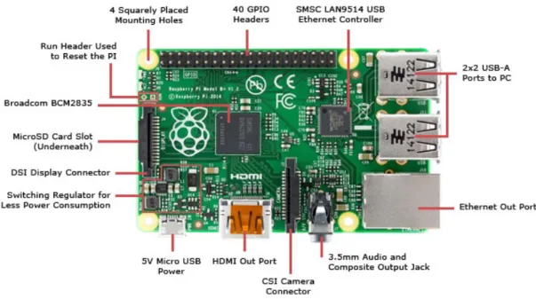
Raspberry Pi is a credit-card sized micro-computer, developed in 2012 at the University of Cambridge's Computer Laboratory, Runs Linux as operating system with the option to have a graphical user interface, and provide some useful inputs, such as USB ports, HDMI port, RJ45 port, audio port and GPIO (General Purpose Input / Output) connectors. These GPIO connectors allows developers to attach other hardware components, such as sensors, motors, leds and displays.
Raspberry Pi can be used for a variety of things, such as a personal computer, a web server, or a device controller where the setup steps are simple. The operating system is downloaded to an SD card, then user configures some minor variables, such as operating system language, keyboard layout and drive setup management. After that, additional packages, such as compilers and libraries, can be added (Brock, Bruce, & Cameron, 2013).
It’s a powerful computer, and when compared to desktop increased-sized solutions, it’s relatively cheap. This companion hardware it’s really useful for this dissertation because of its size, price and included functionalities (Saraiva, 2015).
2.2.2 Flight Controller
Some UAV flight controllers use hardware configurations based on existing projects and 3DR Pixhawk is one of them. ArduPilot is a full-featured open source project, licensed by GNU General Public License version 3 (GPLv3) that supports “from conventional airplanes, multirotors, and helicopters, to boats and even submarines” (Ardupilot Dev Team, n.d.-a). ArduPilot supports several types of UAV’s such as fixed wings, multi-rotors and UGVs (Unmanned Ground Vehicles). Each type is configured in a single firmware file, which is installed on the Pixhawk main processor. This flight control board has some embedded sensors
to provide useful data to Ground Control Station (GCS): a gyroscope, an accelerometer, a barometer and a magnetometer. (Saraiva, 2015) It has the option to add a Global Position System (GPS) sensor to provide location data, such as latitude, longitude, altitude and speed. To perform guided missions, a GPS module is required in order to specify waypoints. This autopilot is fully programmable and can have First-Person View (FPV) camera gimbal support and control, Radio Controlled (RC) channel inputs and other sensors. The built-in hardware failsafe uses a separate circuit to transfer control from the RC system to the autopilot and back again. This prevents crashes by safely land on the ground (Bin & Justice, 2009). In this dissertation, a 3DR Pixhawk flight controller was used with ArduPilot available firmware. In order to transfer data to Raspberry Pi, Pixhawk uses an USB connection.
2.3 Control and Communication
In order to control an UAV, it’s necessary to have intermediary components between UAV itself and piloting user. Such components are essential for piloting because they determine the behavior of an UAV.
2.3.1 Radio Controller
Piloting an UAVs can be quite a challenge for novice pilots, because an UAV can fly in various 3D space directions: left and right, to the front and back, up and down. The simplest and fastest way to start controlling an UAV is using a radio controller. A radio receiver on the UAV is needed to receive radio frequency (RF) data. This data is transmitted by a radio transmitter, controlled by the user, to control UAV’s attitude.
2.3.2 Ground Control Station
A Ground Control Station (GCS) is an essential UAV monitoring and controlling tool. It provides user relevant flight data, read by flight controller sensors. Can be used to track down UAV location by reading GPS data, perform autonomous tasks, calibrate sensors, pre-flight tests, and so on. It’s a required tool for ground operation tasks, used before, during and after UAV flights.
There are various Ground Control Stations software available for Windows and Linux operating system environments, such as Mission Planner, APM Planner and QGroundControl. In order to send and receive data between UAVs and GCS, both must have telemetry equipment, such as
Wi-Fi or Radio Frequency transmitters and receivers. This data is encrypted and sent by a common message type via MAVLink protocol.
2.3.3 MAVLink Message Protocol
MAVLink is a header-only message protocol that uses group of messages to transmit data between the UAV and GCS. It is designed to be reliable, fast and safe against transmission errors. It was first released in 2009 by Lorenz Meier under the LGPL license (Murilhas, 2015; Scherer, 2015). Each message is byte-encrypted with sensor related content, which can be interpreted by Ground Station Control or by Raspberry Pi, which will serve as a message intermediary between Pixhawk and GCS. Commands like take off, raise or decrease altitude (throttle increase or decrease, respectively) are sent by GCS and interpreted by Pixhawk to perform desired action.
Figure 2.3 – MAVLink Message Structure (“MAVLink Micro Air Vehicle Communication Protocol - QGroundControl GCS,” n.d.).
2.4 Distance Sensing
Distance sensing can be useful for many UAV applications, such as ground altitude measurement, UAV terrain shape following, object detection and environment mapping. The use of distance sensors on an UAV extends its features for user determined purposes. There are various types of distance sensors, and each one has its features, restrictions and limitations. The sections 2.4.1 to 2.4.4 describe researched distance sensors, their applications and differences.
2.4.1 Light Detection and Ranging (LiDAR)
A Light Detection and Ranging (LiDAR) sensor is a measurement technology, which is based on a precise measurement of the time delay between the transmission of a pulsed optical laser light signal and its reception (Duh, n.d.). This allows UAV to produce environment mapping, by analyzing objects that are close or far from UAV current position. This sensor produces two types of light signals: Reference signal fed from the transmitter and a received signal reflected
from the target. The time delay between these two signals is calculated through a signal processing method, known as correlation. These correlation process accurately calculates the time delay, which is translated into distance based on the speed-of-light constant (“LIDAR - Technology and System Hardware Overview,” n.d.). Each LiDAR for each application works at different electromagnetic wavelengths. Meteorology LiDARs usually work on ultraviolet (250 nm) and infrared (1500 nm to 2000 nm) wavelengths. For terrestrial mapping, at near-infrared wavelengths (Duh, n.d.). The figure 2.4 shows an example of the electromagnetic spectrum and where terrestrial LiDARs wavelengths are located.
Figure 2.4 – Electromagnetic spectrum and LiDAR wavelength comparison (Duh, n.d.). For pulsed LiDAR lasers, to obtain object distances and range resolutions, the equations are (2.1) and (2.2) are used:
𝑅𝑅 = 𝑐𝑐
2𝑡𝑡(2.1)
where 𝑅𝑅 means the distance, 𝑐𝑐 the speed of light value (~299,792,458 m/s) and 𝑡𝑡 the time delay between transmitting and receiving the light pulse (in ns), and
∆𝑅𝑅 = 𝑐𝑐
∆𝑡𝑡2 (2.2)where ∆𝑅𝑅 is the range resolution, 𝑐𝑐 the speed of light and ∆𝑡𝑡 resolution of time measurement (in ns) (Duh, n.d.).
LiDAR measures a distance of 1,01 m from an object or surface and the real distance value is 1 m, the LiDAR reading accuracy is 1 cm (Value read - Real value = LiDAR accuracy). Range resolution is, for example, on environment mapping, a LiDAR sensor can generate a graph called “point cloud”. And each point means a read distance. Range resolution is the difference between points on a point cloud graph and for a terrain elevation model, “it’s the accuracy of the elevation”, or by other words, how far is the model measurements are from the real terrain elevation (Schmid, Hadley, & Wijekoon, 2011).
Figure 2.5 – LIDAR explanation (Lightware, 2016).
2.4.2 Sound Navigation and Ranging (SoNAR)
SoNAR is a measure technology based on sound waves. This sensor’s principle is the measurement of “bouncing acoustic waves” that hit objects, and by measure its time delay between sound transmission and echo reception of those acoustic waves, it’s possible to determine object distance. A SoNAR has various applications, but it’s commonly used on ships “to measure the depths” of water surfaces, animals or objects (Rouse, 2011). A SoNAR sensor is composed by “an acoustic wave pulse generator, a transducer for transmitting acoustic waves in narrow beams, an acoustic pickup, a set of amplifiers and a delay timer” (Rouse, 2011). Sound waves propagation speed varies according to the environment. A SoNAR sensor can be more useful on water environments other than outdoor environments, because sound waves propagation speed on water is faster than outdoor environment. The distance from an object is measured by sound waves echo time delay. The figure 2.6 explains how a SoNAR sensor works.
Figure 2.6 – SoNAR principle (Radio-Electronics, 2014).
SoNAR sensors are commonly used in fishing ships in order to locate fish shoals. It is also used on submarines to detect objects and other vessels. On medicine field, SoNAR sensors are used to detect diseases or to monitor unborn child. Radio waves are reflected differently according to different body parts or organs (Scholastic Inc, n.d.).
2.4.3 Radio Detection and Ranging (RaDAR)
RaDAR is another measurement technology based on radio waves. It has the same principle of and LiDAR SoNAR sensors, which consists in detecting objects based on the reflected emitted signals. RaDAR sensors have an antenna, a transmitter and a receiver. The transmitter generates the radio wave. When that wave hits an object, it “bounces” back. The reflected signal is detected and classified as radio echo by the antenna. Then, the receiver amplifies that signal to increase its strength. The radio waves travels at speed of light. RaDAR sensors are used for both military and civilian purposes. Commonly, it’s used in planes and ships in order to locate other ships or aircrafts and to prevent collisions. RaDAR sensors are also used for meteorology purposes, such as weather predictions. And when combined with LiDAR sensors, this hybrid solution can help studying storm directions and hurricane locations. A Doppler RaDAR is used to determine storm directions, and it’s “based on the principle of the Doppler effect”. The figure 2.7 explains the Doppler Effect on reflected radio waves.
Figure 2.7 – Doppler effect (NCS Pearson, 2016).
The Doppler Effect explains that the “frequency of a wave changes as the source of the wave moves toward or away from the receiver”. This means that reflected radio waves with different frequencies can determine the source or stationary observer direction by analyzing reflected waves. The Doppler RaDAR sensors are also used by police cars to determine the car speeds. (Scholastic Inc, n.d.).
2.4.4 Distance sensors comparison
The three researched distance sensing technologies have its own features, restrictions and limitations. Choosing the right sensor depends on its purpose of measurement. Some known companies use different distance measurement sensors in order to accomplish same goals: object sensing and avoiding. Google company and its self-driving car uses a LiDAR sensor as primary sensor to “see” the area around the car for autonomous driving. Google’s current solution on object-aware cars can sense objects from 30 m to 200 m (CleanTechnica, 2016). Tesla company uses RaDAR sensors on its autopilot featured cars, once this, sensors can detect objects on harsh environments such as snow, rain and dust while a LiDAR could have some problems in these conditions (Davies, 2016). The Annex D explains differences between these three sensors. In this dissertation, the use of a LiDAR sensor was chosen for having a long distance measurement, a light weight and an affordable price. In order to perform SAR operations, an UAV must be capable of “seeing” objects with high accuracy. Choosing a LiDAR sensor was the solution found to meet the requirements of this dissertation’s main goals.
Chapter 3
UNMANNED AERIAL
VEHICLE
In this chapter, all necessary components description for a successful UAV building are present. Common parts and electrical components explained, what role they have on an UAV, alongside with technical explanations and pre-flight calibrations.
3.1 UAV Composition – Common Parts
In order to perform this dissertation experimental tests, there was a need to build a custom multirotor-typed UAV. The subsections 3.1.1 to 3.1.5 define which materials and components are commonly used to build an UAV with described parts for an initial and base configuration.
3.1.1 Frame
For every custom built UAV, this part must be the chosen first (Benson, 2015). There are various types of multirotor frames from bicopter (two rotor UAV) to octacopter (eight rotor UAV) (O. Liang, 2004). The frame is the UAVs chassis that is used to support all payload installed in an UAV. It’s composed by the “arms, landing gears, rotor mounts and central plates” (Saraiva, 2015). The frame choice is an important one because each frame type has different rotor numbers. A tricopter frame appropriated for three-rotor UAV and an octacopter for eight-rotor UAV. More eight-rotors mean a “higher energy consumption but also leads to a higher flight stability” (Saraiva, 2015). Frames can also have different sizes. The frame size is measured by its diameter, which is normally comprehended between 350mm and 700mm (Benson, 2015). There are two multirotor frame configurations: flat and coaxial. Flat configuration means that every arm can only support one rotor. If the frame has four arms, its meant for a quadcopter, which is a four rotor UAV. Coaxial configuration means that every arm can have a secondary rotor, above the initial one. A four arm frame in a coaxial configuration can support two rotors: the first one installed like flat frame configuration, and the secondary installed below primary rotor. For example, in a coaxial frame configuration, a three arm frame makes a hexacopter and a four arm frame makes an octacopter. For quadcopters, hexacopters and octacopters, there are two more possible frame arm configurations: ‘X’ and ‘+’. This is determined what style is desired by choosing how frame center-to-front direction can be presented. In this dissertation, a flat configuration and ‘X’ quadcopter-typed UAV was used (O. Liang, 2004).
Figure 3.1 – Differences between ‘X’ and ‘+’ configurations (Ardupilot Dev Team, 2014a).
3.1.2 Rotors
The main function of rotors is to lift the “frame off the ground, hover” and by slightly adjusting angular velocity of rotors, an UAV can fly on every space direction (“How to Build a Drone - A Definitive Guide For Newbies,” n.d.; Luukkonen, 2011). A rotor is composed by its casing, shaft, which sizes can vary. Rotors can have different types, which can be brushed or brushless. The figure 3.2 shows the style difference between rotor types.
Figure 3.2 – Different types of rotors (Benson, 2015).
Brushed rotors “spin the coil inside a case with fixed magnets mounted around the outside of the casing”. Brushless rotors work the other way around: “the coils are fixed either to the outer casing or inside the casing while the magnets are spun” (Benson, 2015). In the UAV market, it’s commonly used brushless DC motors.
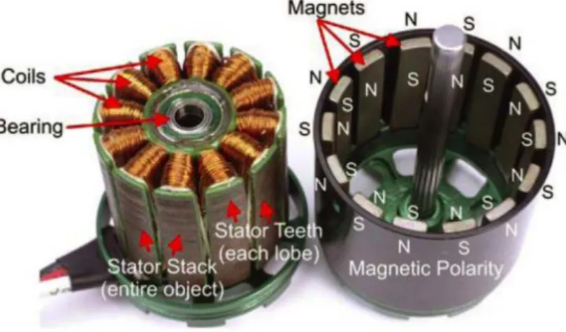
Figure 3.3 – Brushless DC motor (Kwan, 2016).
These types of rotors can have different sizes, measured by rotor height and diameter. Rotation clockwise or counter-clockwise, rotation speeds also vary between sizes, and are measured by KV rating. The KV value of a rotor specify “how fast it will rotate for a given voltage” (Benson, 2015). Rotor speeds are measured in rotations per minute (or rpm). Low KV rotor values (comprehended between 500 and 1000) are used to increase UAV in-air stability. High KV rotor values (1000 and 2500) are used for racer and acrobatic UAVs. For most multirotor UAVs, low KV rotor values are preferred. If a rotor has a KV value of 800 (or 800 rpm per volt), for a given input voltage of 11.1V, it will spin at: 800 × 11,1 = 8880 rpm (Benson, 2015).
The rotors are mounted on every arm end of the frame, with rotor shaft pointed up. For a coaxial frame configuration, the secondary rotor is mounted with rotors’ shaft pointed down. There are advantages and disadvantages about using a coaxial configuration. It can save space, make frame foldable or even land safely a rotor fails, but has a 10 to 20% efficiency loss because the lower rotor is “just turning in already sped-up air” (O. Liang, 2004).
3.1.3 Propellers
The propellers are the top-end part of all rotors. In order to lift an UAV, propellers create downwards air flow allowing enough strength to take-off. To choose the right propellers, it’s important to check their diameter size and pitch values. For most UAV configurations, propellers with two blades it’s commonly used. Smaller the propeller, smaller the inertia created, which can be adequate for acrobatic flights because it’s “easier to slow down and speed up” the blades. On the contrary, bigger propellers are used for a more stable flight because takes
more time to quick speed-ups and slow-downs. (Benson, 2015; “How to Build a Drone - A Definitive Guide For Newbies,” n.d.)
There are two types of propellers, clockwise and counter-clockwise, which design varies according to rotation direction. Clockwise propellers must be installed on clockwise rotation rotors and vice-versa for counter-clockwise propellers. This verification is very important because a mistaken installation of propellers can lead to an instant flip at UAV’s take-off. For example, a counter-clockwise propeller mounted on a clockwise rotor generates upward air flow, i.e., instead of pushing air downwards, it pushes air upwards.
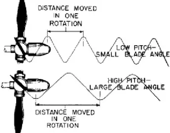
In order to achieve thrust, propellers must have a certain pitch value to push air downwards at a certain rotor speed. The pitch value is related to a propeller’s “angle of attack”, which means the angle value a propeller “attacks” the air. A higher pitch value means a higher angle between the blades and propellers diameter center, a therefore a higher angle of attack (Benson, 2015) (Bristeau, Martin, Salaün, & Petit, 2009). The figure 3.4 represents a comparison between a high and low pitch propeller and how can it can make a difference when taking-off an UAV.
Figure 3.4 – High and low pitch values propellers differences according to distance moved (“Constant Speed Propellers,” n.d.).
3.1.4 Electronic Speed Controllers
An Electronic Speed Controller (ESC) is the bridge between rotors and flight controller. Controls rotor speed and direction. An ESC is known for transforming electric current from battery that outputs Direct Current (DC) to Alternating Current (AC). The UAV’s rotors only accept AC type of current. The signal is pulse-modulated, described as Pulse-Width Modulation (PWM) which means that “the pulse has always the same maximum and minimum amplitude and the duty cycle is the only variation” (Murilhas, 2015). An ESC has maximum current and tension values, so the right ESC must be chosen accordingly with rotor’s maximum current draw and voltage input. For example, if rotor’s specification has a maximum current draw at top speed of 24 amperes (A), the ESC attached to this rotor must have a maximum current draw of 24A or above. It is recommended that ESCs always have a threshold between rotors maximum current draw of rotors and ESC itself (Marinescu, 2013). This means that for the same rotor, a 30A ESC should the right choice to make. Connected and controlled by flight controller, it determines how much current should provide to a single rotor, and therefore, controlling rotor’s rotation speed. A single ESC controls a single rotor. The connections made between ESCs outputs and rotors inputs controls rotor’s rotation direction (Benson, 2015) (Saraiva, 2015). Some ESCs have a Battery Eliminator Circuit (BEC) component to convert input voltage to 5V which can power a RC receiver in order to, for example, test the RC input and Rotor/ESC response.
3.1.5 Power Supply
In order to fly an UAV, an energy source is needed. For most UAV uses, lithium polymer batteries are used (LiPo batteries), and they are known for their high power capacities and low pack weights. These LiPo batteries are composed by cells. Each cell has a nominal voltage value of 3.7V. And these cells are normally connected in series, but they can also be connected in parallel to achieve a desired power output (Patel, Patel, Faldu, & Dave, 2013) (Schneider, 2012). For example, if a battery has three cells connected in series, it’s called a 3S LiPo battery. LiPo batteries are categorized by its power capacity and C-rating. Power capacity is measured in miliamperes per hour (mAh). Higher power capacity value means longer flights, but also an increase in weight payload values. And increased weight values means more to lift, resulting in an increased power consumption, affecting flight times at the same time (G. C. T. Liang, 2015) (Marinescu, 2013). C-rating is the battery discharge level and measures how quick the battery can output power. If a 5800mAh battery has a discharge rate of 25C, which means 25 times battery capacity (C), the battery can output up to a maximum current draw of 145A (25 × 5800 = 145). LiPo batteries have also a burst current C-rating. Measuring the rotors current draw at mid throttle and full throttle it’s important to verify if a certain battery is appropriated for the UAV (Marinescu, 2013) (Patel et al., 2013). To measure a LiPo battery, a cell voltage meter is needed. A fully charged battery means all cells must measure 4.2V. A discharged battery measures approximately 3.74V-3.75V (Salt, n.d.).
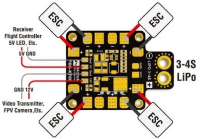
To ensure power to all ESCs and rotors, there is the need to distribute battery power. In order to accomplish that, a Power Distribution Board is needed (PDB). Some frame plates have an embedded PDB. The PDB example figure 3.7 demonstrates how to connect ESCs and other components.
Figure 3.7 – PDB example (BuzzHobbies, 2016).
3.1.6 Set-up Model
In this dissertation, a quadcopter-typed UAV was used, with a ‘X’ mounted orientation and hexacopter plates (with embedded PDB) for an increased middle frame space. This personalized configuration allows extra components addition. The common parts used were:
• 2 unit. of Hexacopter frame plates; • 4 unit. of Low-KV rotors (350KV);
• 4 unit. of ESCs with 20A of maximum current draw; • 4 unit. of 1345 Carbon fiber propellers;
3.2 UAV Composition – Flight Controller
The flight controller is responsible for mostly all UAV actions and behaviors. In this dissertation, a 3DR Pixhawk was used. Pixhawk is an “independent, open-hardware project” to provide UAV autopilot features commonly used for civil, industrial and military purposes (“Pixhawk Autopilot - Pixhawk Flight Controller Hardware Project,” 2016). Running an internal real-time operating system called NuttX (BYOD, 2015), Pixhawk is known to be an improved and updated version of ArduPilot Mega (APM) (Saraiva, 2015) and it has the perfect conditions to meet this dissertation goals. The table 3.1 shows some Pixhawk hardware specifications:
Table 3.2.1 – Pixhawk hardware specifications (BYOD, 2015).
Figure 3.8 – Pixhawk input options (“Unmanned Hawk Autopilot Kit,” n.d.).
CPU 168 MHz Cortex
RAM 256 KB
Flash memory 2 MB
Sensors 3D Accelerometer, Gyroscope,
3.2.1 Firmware
Every flight controller has an internal firmware. This firmware is responsible for UAV control and to provide user relevant data read from internal and external sensors. Each firmware is configured accordingly to UAV type. A quadcopter configured firmware is different from a fixed-wing UAV. The firmware used was ArduCopter, in its 3.3.3 version for Pixhawk. It’s an open-source firmware that allows UAVs to preform autonomous tasks and missions, real time data and control, UAV altitude hold, hovering stabilization and other features. This firmware, totally pre-configured for quadcopters, requiring no programming at all, includes various flight modes to perform certain tasks or to achieve UAV desired behavior (Saraiva, 2015). The Annex A is related with available and experimental tested flight modes.
3.2.2 Attitude
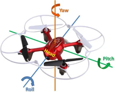
An UAV can fly in every direction by controlling 3 different axes: Longitudinal, lateral and vertical axis. Vertical axis movements represent upwards and downwards UAV’s movement, called Throttle movement. Left or right movements are represented by UAV’s rotation on longitudinal axis, also called Roll movement. And lateral rotations axis represents Pitch movements, or UAV’s dislocation to the front or to the back. Yaw movements means UAV rotations on vertical axis, and it can be clockwise or counter clock-wise rotations. Every change on Roll, Yaw, Pitch or Throttle can be also called as an Attitude change. The figure 3.9 describes visually what axis are controlled by Roll, Pitch and Yaw movements (Kwan, 2016).
3.2.3 Internal Sensors
Pixhawk’s flight controller has internal sensors in order to maintain a self-stabilizing flight. These internal sensors are within a small electronic board called Inertia Measurement Unit (IMU). Pixhawk’s IMU board has a 3-axis gyroscope, which measures UAV’s angle of rotation and a 3-axis accelerometer, measuring linear accelerations. The IMU board is responsible for keeping an UAV stable in the air, by reading its sensors data and sending ESCs signals to change rotors speeds, increasing or decreasing, in order to achieve a horizontal balance on longitudinal and lateral axis (Benson, 2015) (Kwan, 2016). These sensors need calibration in order to set default IMU parameters when an UAV is standing still on the ground before flying for the first time.
For maintaining current UAV altitude, a barometer is needed in order to analyze changes on atmospheric pressure, since it changes when UAVs altitude also changes above sea level (Benson, 2015). The combination of the IMU and barometer readings can assure a self-stabilizing hover flight on non-windy environments.
To calculate UAV’s current heading, a compass or magnetometer is used. By using earths’ magnetic field, a compass can determine which direction is UAV’s heading.
Figure 3.10 – IMU possible readings on UAV’s behavior changes (Benson, 2015).
3.2.4 External Sensors
External sensors add Pixhawk’s flight controller useful features in order to improve UAV’s flights and to achieve certain goals. These sensors are not embedded within Pixhawk’s main board and therefore connections have to be made.
Global Positioning System
In order to perform autonomous tasks, such as waypoint-guided missions or to save home location, a GPS sensor is needed to give accurate reading about UAV’s current position in 3D space. With GPS, the user can track down UAV’s current position in real time. Also, it gives a more accurate reading about UAV’s current altitude above sea level, and on windy environments, GPS readings improve UAV’s current position and altitude holding. GPS sensor it’s indispensable for outdoor UAV flights, since failsafe mechanisms and other autonomous tasks relies almost completely on GPS readings.
Light Detection and Ranging
A Light Detection and Ranging sensor, or a LiDAR sensor is commonly used for environment mapping and altitude precise measurements. It’s useful for an UAV to maintain a predefined above ground altitude in order to perform precise hoverings or automated UAV landings (Lightware, 2016). In this dissertation, a laser altimetry LiDAR was used. There are various LiDAR altimeters that are compatible with Pixhawk’s flight controller. LIDAR-Lite v2 and SF11/C LiDAR, produced by PulsedLight and Lightware respectively, are good choices for UAV distance measure purposes. In Annex C, table C.1 represents a comparison between LIDAR-Lite and SF11/C LiDAR, by stating full specifications of both LiDAR altimeters. For this dissertation, it was used SF11/C LIDAR altimeter for future work usages. For having higher distance measurement than LIDAR-Lite, SF11/C LIDAR can also be used for other applications that require a high distance measurement value, such as environment mapping. Its maximum distance measurement guaranteed a safe distance when “reading” and locating objects in sight. This LiDAR sensor was the chosen solution to fly an UAV outdoors and to perform search and rescue operations.
Pixhawk’s flight controller is prepared to read LiDAR data in order to perform tasks described above if this sensor is mounted down-pointed below UAV’s frame’s infra-plate structure. In this dissertation, the sensor was placed on UAV’s upper-frame plate and is front-faced, matching UAV’s front (also called “nose”) heading. Pixhawk’s above ground altitude holding features using LiDAR sensors were disabled to prevent unwanted UAV behaviors.
3.2.5 Calibrations
In order to fly an UAV for the first time, some pre-flight calibrations must be made. The most important sensors for calibration are the accelerometer and compass / magnetometer. These internal sensors (compass can be an external sensor if GPS is used), as said before, are the main reason for UAV’s on-air stabilization. In order to calibrate these sensors, a Ground Control Station is needed to enter calibration options. Radio transmitter calibration is also needed. The Mission Planner GCS software was used to perform pre-flight calibrations mentioned above. Each calibration option links to a sensor (except for RC calibration). The subsections 3.2.5.1 to 3.2.5.3 describes what steps should be made to perform a successful sensor and RC calibration.
Accelerometer Calibration
In order to calibrate UAV’s accelerometer in Mission Planner GCS, the user must go to “Initial Setup” > “Mandatory Hardware”, and then select “Accel Calibration” from the menu on the left and click on “Calibrate Accel”. Then a step-by step window pops up, and by following the instructions, user must grab the UAV and perform this steps, one by one, as requested (Ardupilot Dev Team, n.d.-b):
Figure 3.11 – All UAV positions required for successful calibration (Ardupilot Dev Team, n.d.-b).
When all steps described on the figure 3.11 were made, a successful calibration message should appear at the end of the process.
Compass Calibration
Compass calibration can also be made on Mission Planner GCS. Under “Initial Setup” > “Mandatory Hardware”, there is an option called “Compass”. By selecting UAV’s flight controller pre-defined options (which in this case, it’s Pixhawk) and by checking “Obtain declination automatically” and “Automatically learn offsets” checkboxes, the user must
The image 3.12 shows the next pop-up window that should appear right after clicking on “Live Calibration” button.
Figure 3.12 – Mission Planner’s compass “Live Calibration” window (Ardupilot Dev Team, n.d.-c).
On this window, the user needs to perform the exactly same steps as mentioned on Figure 3.11,
i.e., rotating on every UAVs axis and angles, to acquire calibration samples. When enough
samples were acquired, the compass calibration ends and save its preferences.
RC Controller Calibration
Radio controller calibration is also an important step before flying an UAV for the first time. This calibration sets maximum and minimum limits of RC channels for user’s current RC transmitter. To perform RC calibration, also on Mission Planner GCS, the user must go to “Initial Setup” > “Mandatory Hardware” and then select “Radio Calibration”. If radio transmitter and receiver were bond, green bars should move when the user also move RC transmitter sticks. In order to start calibration, the user must click on “Calibrate Radio” button. Now, the user must move all sticks to its maximum and minimum position, for every UAV possible behaviors (Yaw, Pitch, Roll, Throttle) and change switches to high and low positions of active additional channels. When all of the steps mentioned before were made, the user must click again on “Calibrate Radio” in order to save maximum and minimum RC transmitter limits for a determined UAV.
3.3 UAV Composition – Raspberry Pi
Raspberry Pi is the intermediary companion hardware between user’s command inputs from a Ground Control Station and Pixhawk’s flight controller. It is running Raspberry Pi’s Raspbian operating system version. Raspbian is a Debian-based Linux operation system, fully optimized for Raspberry Pi’s hardware, developed by Raspberry Pi Foundation. It has some pre-installed tools such as Java SE Platform, which is useful to run this dissertation “Sense and Avoid” algorithm. (Raspberry Pi Foundation, 2012a) The chapter 5 of this dissertation explains what features “Sense and Avoid” algorithm has and how it will behave when facing objects in UAVs current trajectory path. A Raspberry Pi 2 Model B was used and it’s mounted on UAV’s upper frame plate. This Raspberry Pi’s version has 1 GB of RAM, 900 MHz quad-core CPU processor and 4 USB ports (Raspberry Pi Foundation, 2012b). Some USB ports were used to connect Pixhawk, to exchange MAVLink data between background algorithm and Pixhawk, and a Wi-Fi dongle to connect to a GCS. It requires 5V powered by a mini-USB cable. This credit-card sized computer was chosen to perform this dissertations’ main goals because of its size, performance, big hobbyist internet community and for being a low-cost solution (Murilhas, 2015).
3.4 Connections & Final Build
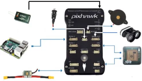
Pixhawk flight controller will be installed on the inferior plate. After UAV full building, it’s difficult to reach Pixhawk input connections, and to avoid that, some essential components need to be connected before mounting upper frame plate. The figure 3.14 shows the main connections to Pixhawk.
Figure 3.14 – Pixhawk’s essential main connections. Adapted from: (Murilhas, 2015). The figure 3.15 represents the custom-built UAV totally configured and ready to fly, including all the previous described components. To help at UAV landings, a landing gear was installed.
Chapter 4
CONTROL AND
COMMUNICATION
UAV’s possible control and communication modes are described in this chapter, each one presenting its features and limitations. MAVProxy was also mentioned as a gateway between control interfaces.
4.1 UAV Control
There are two ways to remotely control an UAV. It can be controlled by a basic Radio Controller, or a Ground Control Station. Some features are only available if the user have a GCS software. Each controlling method has its own way of communication between Pixhawk and the user. For most civilian purposes, RC control is mostly used (Murilhas, 2015). An UAV has two different rotors state: ARMED and DISARMED. ARMED state means UAV is ready to take off. DISARMED state totally disables rotors and is unresponsive until ARMED. In order to “arm” an UAV, specific RC input combinations must be made. In case of GCS control, a MAVLink command can be sent.
4.1.1 RC Control
Radio controlling an UAV, as describe before on this dissertation’s Radio Controller chapter subsection 2.3.1, it is the bottom basis to start controlling an UAV. The user has manual control of UAV’s Pitch, Roll, Yaw and Throttle behaviors. Each of this behaviors are associated with a radio frequency channel (Saraiva, 2015). In order to start controlling an UAV, a minimum 4-channel radio receiver and transmitter is needed. Other 4-channels are used to start missions, change flight modes or to control servos. The RC controller used in this dissertation works in 2.4GHz frequency band and uses Pulse-Width Modulation (PWM) to send its signals. The pulse length determines the channel’s output value. PWM signals’ width varies between 1000 µs and 2000 µs, corresponding to maximum (Full Forward) and minimum (Full Reverse) widths respectively. The PWM pulse width neutral value is 1500 µs. The figure 4.1 describes visually how PWM works.
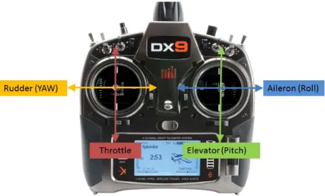
There are two RC configuration modes: Mode 1 and Mode 2. The Mode 1 RC controller has the Roll and Pitch controls on the left stick of the controller, and Throttle and Yaw controls on the right stick of the controller. On a Mode 2 RC controller, the left sticks controls Yaw and Throttle, and the left stick, Pitch and Roll. The use of a RC controller only allows UAV control in user’s Line of Sight (LoS). The figure 4.2 shows a Mode 2 RC controller example, and what the direction that user should move sticks in order to increase or decrease described UAV known behaviors.
Figure 4.2 – Mode 2 RC controller example (Robert, n.d.).
4.1.2 Ground Control Station
The Ground Control Station is the “headquarters” of UAV’s operations. It allows user to control and communicate with an UAV. It is possible to update flight controllers’ firmware, change predefined parameters, plan waypoint-guided missions, analyze telemetry data, calibrate internal and external sensors, calibrate radio controller channels for minimum and maximum stick limits, check sensors for failures or bad behaviors, check battery status and to send MAVLink commands, which are interpreted by Pixhawk. It also allows for UAV in-flight status, such as real time position monitoring and control (Murilhas, 2015). GCS is the most useful component for controlling, communicating and monitoring an UAV. For this dissertation, Mission Planner GCS software was used. Mission Planner is a full-featured open-source ground control station with a large community support. It was created by Michael Oborne for the ArduPilot open-source autopilot. Available for Windows operating system only,
(Ardupilot Dev Team, n.d.-d). Mission Planner GCS is not only for UAVs (Plane and Copter firmwares) but also for UGVs (Rover) (ArduPilot Dev Team, 2014). In this dissertation, the use of Mission Planner software provided useful test aids, such as GPS flight path and LiDAR sensor reading and data logs, useful to elaborate results from testing environments.
Figure 4.3 – Mission Planner software’s main view (ArduPilot Dev Team, 2014). The figure 4.3 shows Mission Planner software on its main view (Flight Data). In this view on the figure’s caption number 1 (left side), it is possible to read IMU sensors information, such as UAVs inclination and heading, vertical speed and altitude; GPS fix, battery level, communication signal strength, current flight mode and UAV’s rotor state.
In the figure’s caption number 2 (right side) there is a two-dimensional map (provided by Google Maps) where it is possible to see UAV’s current GPS position and satellite count, pre-programmed waypoints and monitor in real time an UAV’s flight.
4.2 UAV Communication
UAV communication is a critical requirement in UAV controlling and monitoring (Saraiva, 2015). It establishes the bridge between user controlling commands and UAV responses. There are various types of communication methods in order to exchange data between flight controller and GCS. Each method has its own components dependency and limitations. The subsections
1
4.2.1 to 4.2.3 describe each communication method, what component requirements need to be met and its features and limitations.
4.2.1 Wi-Fi Telemetry
Wireless communication between user and flight controller, using Wi-Fi technology, can only be made with an intermediary component like Raspberry Pi. In order to exchange data between GCS and UAV, Raspberry Pi must have a Wi-Fi dongle connected. Then, in Raspberry Pi, there is the need of creating a Wi-Fi hotspot, also known as Wi-Fi local network, for GCS to connect to it. The Wi-Fi dongles work at radio frequency band of 2.4 GHz.
Although, there are some limitations concerning this type of Wi-Fi connection to get telemetry info, the dongle installed on Raspberry Pi must have a good Wi-Fi antenna power for a higher maximum range. Maximizing the Wi-Fi range leads to maximizing the distance between UAV and GCS without losing communications. In order to connect to Raspberry Pi Wi-Fi hotspot, the user must connect to SSID of the respective hotspot (Saraiva, 2015). Using WPA2 encryption method on Wi-Fi hotspot increases security between communications because it avoids non-wanted users to access our Raspberry Pi Wi-Fi network.
4.2.2 Radio Telemetry
Radio telemetry is another method for communication between Pixhawk and GCS. By using radio telemetry, the receiver (Rx) is directly connected to Pixhawk’s flight controller, and the transmitter directly connected to GCS as well. These radio transmitters and receivers are already prepared to exchange MAVLink data between them, if the chosen device supports ArduPilot messaging protocol, MAVLink. There are various radio telemetry devices, and each one has different communication frequencies, range, power consumption and cost. Mostly radio telemetry devices operate at 433 MHz (which is legal radio frequency to use in Europe) (Oliveira & Gersão, 2015) (Barbatei, 2014). In this dissertation, a 3DR Radio Telemetry kit was used for its price and compatibility. It has a 1.6 km communication range, and it was just used for test purposes. An XBee-PRO 868 has a large range (40 km), which can be very useful for search and rescue operations, with the disadvantage of being more expensive (Barbatei, 2014).
4.2.3 MAVProxy
In order to establish communication between Pixhawk and “Sense and Avoid” algorithm running on Raspberry Pi, both ends need to use same messaging protocol (MAVLink) to make communication possible (Saraiva, 2015). MAVProxy is a gateway intermediary command-line ground control station. Open-source, developed by Canberra UAV OBC team and it was built in python programming language. MAVProxy is available for Windows, Linux and Mac OS. For being light-weight, this GCS can run on small computers with less effort, such as Raspberry Pi (Saraiva, 2015) (Murilhas, 2015). In this dissertation, MAVProxy will serve as a MAVLink message gateway only. Its main goal is to exchange MAVLink messages between “Sense and Avoid” algorithm and Pixhawk’s flight controller. In order to accomplish that, MAVProxy will be always running on Raspberry Pi, waiting for command inputs supplied by “Sense and Avoid” algorithm. MAVProxy is not a unique controlling station. Other GCS can be connected to Pixhawk and/or Raspberry Pi via Wi-Fi, RC or via Radio Telemetry. MAVProxy is only needed for decision in “Sense and Avoid” algorithm. When no decisions are made, other control methods can override MAVProxy GCS and fly an UAV normally. In chapter 5, “Sense and Avoid Algorithm”, there is a mechanism that forces an UAV to disable any other types of UAV control, in case of object detection and in collision course.
Chapter 5
SENSE AND AVOID
ALGORITHM
This chapter explains the algorithm developed in order to deploy an autonomous object collision avoidance system using distance ranging for UAVs.