I
INSTITUTO POLITÉCNICO DE LISBOA
ESCOLA SUPERIOR DE TECNOLOGIA DA SAÚDE DE
LISBOA
ATTENUATION OF THE CALYPSO® SYSTEM IN A LINEAR
ACCELERATOR
CÉLIA PATRÍCIA DOS SANTOS SILVA
ORIENTADORAS:
DOUTORA MARGARIDA EIRAS, ESCOLA SUPERIOR DE TECNOLOGIA DA SAÚDE DE LISBOA DOUTORA SANDRA VIEIRA, CENTRO CLÍNICO DA FUNDAÇÃO CHAMPALIMAUD
Mestrado em Radiações Aplicadas às Tecnologias da Saúde
III
INSTITUTO POLITÉCNICO DE LISBOA
ESCOLA SUPERIOR DE TECNOLOGIA DA SAÚDE DE
LISBOA
ATTENUATION OF THE CALYPSO® SYSTEM IN A LINEAR
ACCELERATOR
CÉLIA PATRÍCIA DOS SANTOS SILVA
ORIENTADORAS:
DOUTORA MARGARIDA EIRAS, ESCOLA SUPERIOR DE TECNOLOGIA DA SAÚDE DE LISBOA DOUTORA SANDRA VIEIRA, CENTRO CLÍNICO DA FUNDAÇÃO CHAMPALIMAUD
Mestrado em Radiações Aplicadas às Tecnologias da Saúde
(esta versão inclui as críticas e sugestões feitas pelo júri)
V
ATTENUATION OF THE CALYPSO® SYSTEM IN A LINEAR
ACCELERATOR
A Escola Superior de Tecnologia da Saúde de Lisboa tem o direito, perpétuo e sem limites geográficos, de arquivar e publicar esta dissertação através de exemplares
impressos reproduzidos em papel ou de forma digital, ou por qualquer outro meio conhecido ou que venha a ser inventado, e de a divulgar através de repositórios científicos e de admitir a sua cópia e distribuição com objectivos educacionais ou de investigação, não comerciais, desde que seja dado crédito ao autor e editor e que tal
não viole nenhuma restrição imposta por artigos publicados que estejam incluídos neste trabalho.
VII
A
GRADECIMENTOS
Aos meus orientadores, Professora Margarida Eiras pela orientação dada neste trabalho e apoio na resolução de problemas, e Doutora Sandra Vieira pela orientação, partilha de conhecimento, disponibilidade e pela paciência com o meu inglês.
Ao Director Clínico do departamento de Radioterapia, Professor Carlo Greco, por me ter concedido autorização para realizar este trabalho.
Especialmente, à Física Dalila Mateus pela partilha de conhecimento, por me ter ensinado como fazer medições de atenuação de radiação e pela paciência e disponibilidade para comigo.
Aos meus colegas Téc. Bárbara Dias e André Machado que me acompanharam de perto durante esta fase, pela ajuda nas medições e pelos conselhos.
À Técnica Ana Lúcia Silva que me deu o melhor exemplo que podia ter tido como técnica de radioterapia.
Aos meus pais que me diziam em pequena que “se não estudas vais trabalhar para uma loja de santos”.
Ao meu namorado, Hilário Neves, que sempre me deu forças para querer mais e melhor, me impele a sonhar mais alto e consegue tornar qualquer grande problema num pequeno obstáculo.
Aos amigos Nélia Gonçalves e Tânia Carreira por todo o apoio e por me ouvirem nas horas mais difíceis, e à Cátia Silva pelo apoio e motivação que realmente me deu sempre que me dizia que “de todos os meus amigos que se meteram num mestrado, nenhum acabou a tese”. O desafio funcionou.
IX
Introductory note
Accuracy is the keyword when it comes to radiotherapy. More advanced treatments usually take more time, so immobilization is mandatory. However, immobilization does not resolve the intrafraction motion problem, whether it is caused by natural processes such as breathing and heart beating or patient intentional movement.
This question led to the development of the Calypso® 4D Localization System. This is a system that monitors internal movement when treating allowing to interrupt and to correct any shift that occurs during treatment (intrafraction motion). That way it is possible to detect when the patient moves and also to account for internal movement. This technology was recently acquired and installed in Champalimaud Clinical Center. Considering that I am a radiation therapist in this center where the purpose is to ensure good quality of administered treatments, I could not do but to direct this work towards the field in which I dwell daily. It is advisable to study the effect of any new equipment in treatment delivery and that gives the opportunity to acquire and to explore local data. In the first part of this work, a review on state-of-the-art literature is provided (previously submitted in December 2013 and accepted in May 2014), as to allow for a fully comprehension of the subject discussed here: how Calypso® system works, its advantages when compared to other monitoring systems available and how it is being used around the world.
After knowing how Calypso® works, one question is inevitable. In order to monitor the patient continuously an array is positioned above the patient during the treatment and the treatment planning system does not account for that. How much dose does the array attenuate? The second part of this work assesses this subject. A study was performed by measuring the transmitted radiation of several beams (with beam energy, field size and gantry angle variation) with and without the array in the beam path and the attenuation was calculated and analyzed (previously submitted in May).
Finally, the third part of this work studies radiation attenuation in treatment tabletops. It was noted when Calypso® system was being installed that changing the treatment table was part of the installation process. For the system to work properly no electric conductive materials are allowed in the array’s volume detection, as the system functions by electromagnetic detection. Carbon fiber is an electric conductive material so the Varian Exact IGRT tabletop was replaced by a table with the two exchangeable
X inserts kVueTM Universal Tip Insert (carbon fibre) and kVueTM Calypso ® Varian Insert (kevlar).
A study was performed in order to determine if there was any loss in treatment administration quality due to the radiation attenuated in the treatment tabletop. Radiation measurements were performed without tabletop and also with each of the three tabletops (with beam energy, field size and gantry angle variation). Attenuation was calculated for the three tabletops. It was assessed if new tabletops attenuated more or less radiation than the original one, and it was considered if it was adequate not to switch between kVueTM Calypso® Varian and kVueTM Universal Tip tabletops according to the use of calypso system or not, respectively.
It is noteworthy that the Master Commission authorized the presentation of this work as three scientific articles written in English, with the purpose of future publication in international, peer-reviewed journals. In order to do so it respects some criteria related to this objective.
XI
Index
Agradecimentos……… V Introductory note ……… VII Index……… IX
STATE-OF-THE-ART: CALYPSO 4D LOCALIZATION SYSTEM ……… 1
Abstract ……….. 1
Introduction ………. 2
Materials and methods ……… 2
Revision ……….. 3
Discussion ……… 10
Conclusions ……… 13
STUDY ON CALYPSO’S ARRAY ATTENUATION……… 21
Abstract ……… 21
Introduction ……….. 21
Materials and methods ………. 22
Results and discussion ……… 24
Conclusions ……… 26
RADIOTHERAPY TABLETOPS: ATTENUATION STUDY OF THREE DIFFERENT TABLETOPS…………. 31
Abstract ……… 31
Introduction ……….. 32
Materials and methods ………. 33
Results ……….. 34
Discussion ……… 39
Conclusions ……… 41
1
State-of-the-art: Calypso 4D Localization System
Célia Silva a1a2, Dalila Mateus a2, Margarida Eiras, PhD a1, Sandra Vieira, PhD a2
a1 Centro Clínico Fundação Champalimaud, Lisboa, Portugal a2 Escola Superior de Tecnologias da Saúde de Lisboa, Portugal
Abstract
Purpose: Calypso® four-dimensional localization system is a system based on electromagnetic transponders detection enabling precise three-dimensional localization and continuous tracking of tumor target. This review intended to provide information in order to (1) show how Calypso 4D Localization System® works, (2) to present advantages and disadvantages of this system, (3) to gather information from several clinical studies and, finally, (4) to refer Calypso System as a tool in Dynamic Multileaf Collimator studies for target motion compensation.
Methods: A structured search was carried out on b-On platform. The key words used in this research were “Calypso”, “Transponder”, “Electromagnetic Localization”, “Electromagnetic Tracking”, Target Localization”, “Intrafraction Motion” and “DMLC”. Review: Treatment the implanted transponders are excited by an electromagnetic field and resonate back. These frequencies are detected and Calypso software calculates the position of the transponders. If the movement detected is larger than the limits previously defined, irradiation can be stopped. The system has been proven to be submillimeter accurate.
Discussion: Calypso® system has been presented as an accurate tool in prostate radiotherapy treatments. The application of this system to other clinical sites is being developed.
Conclusion: The Calypso® system allows real-time localization and monitoring of the target, without additional ionizing radiation administration. It has been a very useful tool in prostate cancer treatment.
2 Introduction
The main goal in radiation therapy is to deliver a prescribed dose to a target volume while minimizing toxicity to adjacent healthy tissues. One potential way to decrease radiation related toxicity would be to spare more normal tissues (1-5). The latest equipment development now allows us to use more precise and conformal techniques when delivering radiation, such as IMRT (Intensity Modulated Radiotherapy) and IMAT (Intensity Modulated Arc Therapy) techniques. The introduction of these techniques demands for precise target immobilization and localization so there is minimal movement during treatment (6).
New imaging modalities have improved localization and setup accuracy. The possibility to acquire a ConeBeamCT (CBCT) before treatment allows professionals to make adjustments according to the target and surrounding organs position, instead of making adjustments according to boney position (MV planar images) (7-16). CBCT images can be acquired before and/or after treatment delivery or even between beams. Nevertheless, that does not account for movement that may occur during treatment and organ motion is a major obstacle to reducing margins without compromising dose to the target volume (17). Camille Noel et al. studied this pre- and post-treatment CBCT acquisition as a way of predicting intrafraction movement in prostate patients. The conclusion of this study indicated that this imaging acquisition is not a good predictor of intrafraction prostate motion (18).
In order to consider internal movement, various methods have been used for real-time tracking. Methods as fluoroscopy and mega-voltage imaging (associated or not with gold fiducials) have the disadvantage of increasing the radiation delivered to the patient. On the other hand infrared tracking of external markers consider external movement as directly related to internal movement, but this correlation has been proven to be imperfect (7-16; 19-21).
The Calypso 4D Localization System (Calypso Medical, Seatle, WA) is a wireless electromagnetic localization system which aims to target tumors accurately before and during treatment delivery (22).
This review provides information in order to (1) show how Calypso 4D Localization System works, (2) to present advantages and disadvantages of this system, (3) to gather information from several clinical studies and, finally, (4) to refer Calypso System as a tool in Dynamic MLC (DMLC) studies for target motion compensation.
3 Materials and methods
The review was based on literature searched on B-On Platform. The key words used in this research were “Calypso”, “Transponder”, “Electromagnetic Localization”, “Electromagnetic Tracking”, Target Localization”, “Intrafraction Motion” and “DMLC”. The search provided several articles since January 2005. After reading and analyzing the B-On search, a selection of references mentioned in some of these articles was made and also analyzed and included in this review.
The Calypso 4D Localization System
This system has five components: Beacon transponders (specially created for Calypso system), the console, the array, the optical localization subsystem and the monitoring station (23).
Each transponder consists of a sealed glass capsule containing a miniature electronic circuit. Transponders are 8,7 mm length and 1,85 mm in diameterand are biologically inert (6, 23, 24). Typically, three Beacons are implanted in the patient. Only two transponders are necessary for the system to calculate translational movements. However, to have information about rotations a minimum of three transponders is needed (23-25). The transponders resonate when excited with the electromagnetic field generated by the array. Each transponder has a unique frequency response. The transponders are also color coded with their intended position, which allows them to be distinguished individually. Sensors in the array measure the magnetic field strength from each transponder and the software can calculate the location of each transponder
(22, 23, 26, 27).
The console is inside the treatment room. It is a movable unit that gathers a power supply, a computer with the software that calculates transponders location, cables, and the array (23).
The array contains source coils, sensors and infrared targets. The source coils generate the electromagnetic fields that excite the transponders. The sensors of the array receive the resonant signals of each transponder and the infrared targets are detected by infrared cameras (22, 23). The array is positioned above the patient, with minimum beam attenuation (28).
Three infrared cameras are mounted in the treatment room so that the array position is continuously monitored. The array location yields the position of the center of the
4 target, with respect to the machine isocenter. This means that the system calculates the table translation movements that are necessary to have the Beacons positioned at the treatment unit according to the planning CT scan. The positional information is simultaneously displayed and updated in the console as it is in the control area (23, 24, 27, 29) (Figure 1).
Figure 1. Tracking station display: in this example the patient is positioned in (0, 0, 0) Calypso® coordinates (black line) and during the monitoring period beacons’ movements are within acceptable limits (grey zone) whenever the graph is blue, and outside acceptable limits (black zone) whenever the graph is yellow; the actual shift value for the three coordinates is on the screen left side (reproduced by kind permission of Calypso from Calypso System User’s Manual).
Radiation therapists are in the control area monitoring the movement of the target during the treatment delivery through the observation of the data that is being displayed on the monitoring station. Visual and audio alerts warn therapists that the target has exceeded the limits established (23, 30).
5 Advantages (22, 31-35)
• No additional ionizing radiation is delivered to the patient;
• The target is monitored continuously;
• Real-time information is provided so that action may be taken to limit the influence of intrafraction motion (33);
• Three dimensional target tracking;
• Not dependent on target size: the system relates to a virtual point about which the physician defined radiation volume is actually delivered;
• The transponders are implanted directly into the target volume;
• The implantation procedures are generally uneventful and well tolerated by the patients (23);
• Compact;
• Biocompatible;
• Transponders are compatible with Computed Tomography (CT) imaging and, in some cases, megavoltage imaging;
• Connection between Calypso System and Linear Accelerator: the irradiation may stop automatically when the detected movement is superior to the threshold previously defined (available only for Varian Edge Platform);
Disadvantages (23, 25, 29, 30, 36, 37)
• Extra imaging may be needed to assess fully the Planning Target Volume (PTV) and the organs at risk (OARs) – e. g. the system may confirm that the prostate is in the right position, but no information is given regarding the size of the bladder, an image is required to evaluate that OAR;
• Need for implantation;
• Calypso® manual considers a localization volume under the array of 14 x 14 x 27 cm3 space in lateral, longitudinal and vertical directions (32) therefore the Beacons should be placed so that they are inside this volume during treatment;
• Implanted Beacons may result in a problem when MRI follow-up exams are performed: the RF transmitters in the Beacons create huge image artifacts (37);
• Patients with pacemakers should be handled with care;
• After implantation, Beacons stay inside the patient and cannot be re-used;
6 Quality Assurance
The accuracy of the system has been verified to sub millimeter accuracy, in several laboratory and clinical studies.
Balter et al. report the results for several tests focused on the accuracy of transponder localization relative to the array. First a single transponder was positioned at locations up to 8 cm in the X and Y planes from the center position, at Z distances of 8 and 27 cm from the array. A continuous readout of the transponder positions was recorded at these positions for periods up to 20 min. At 8 cm distance from the array the offset after 15 min the readouts were +0,03, +0,05 and -0,09 mm for the X, Y and Z directions respectively. At 27 cm distance from the array after 15 min the readouts were +0,19, +0,22 and -0,2 mm for the same directions, respectively (31).
The experiment was repeated with the beacon in 0,9 % saline solution (concentration that simulates a conductivity environment compared to twice that of human tissue). At 27 cm distance from the array and 8 cm away from the center the readouts after 20s were +0,29, +0,43 and -0,33 mm for the same directions, respectively (31).
After concluding that the system correctly detects one beacon, the experience was repeated at 8 and 27 cm offset from the array, this time with a set of three beacons: at Z distance of 8 cm the offset was +0,17, +0,03 and +0,05 mm and at Z distance of 27 cm the offset was +0,16, +0,18 and +0,12 mm for X, Y and Z, respectively, for both measurements (31).
Ogunleye et al. compared Calypso® system with kV planar imaging for localization of markers. In this case Beacons were the markers to be localized as they are detected by Calypso® system (magnetic resonance) and they are also detected in x-ray image (radio opaque) (38).
A stationary phantom was not aligned in the isocenter. The measured offset of the target isocenter from the correct position as indicated by the Calypso system should be the exact opposite of the OBI shift required to move the target isocenter to the correct position. The values were compared for 30 different phantom positions. The difference between the two systems was 0,4 (δ=0,4); 0,2 (δ=0,3) and 0,4 (δ=0,3) mm in the X, Y and Z directions, respectively (38). The process was repeated with 259 prostate treatment fractions. The difference between the two systems was 0,7 (δ=0,5); 1,1 (δ=0,9) and 1,2 (δ=0,9) mm in the X, Y and Z directions, respectively (38).
7 Action Protocol for Treatment Intervention
The above mentioned target positioning limits are inserted into the Calypso software according to an Action Protocol for Treatment Intervention. Several protocols have been reported.
Shinohara et al. studied five locally advanced pancreatic cancer patients with a 3mm-action protocol. The therapists were to interrupt radiation delivery every time intrafractional motion was greater than 3 mm (17). In a prostate study by Smith et al. the same action level was established (40).
Also in a prostate study by Su et al. a 5 mm shift as threshold was used. A re-localization was to be performed only if the Beacon centroid drifted more than 5 mm for 25 seconds continuously (41).
One of the prone position studies was reported by Shah et al. In this study, therapists were instructed to observe the prostate gland position and intervene when the motion was larger than 3 mm. However, if the motion was transient as peristaltic movement, even if exceeding 3 mm, the therapists should not act. Also, intervention should be between beams (38).
Clinical Applications
The Calypso 4D Localization System has been approved for marketing by FDA for target organ positioning and monitoring during delivery of radiation therapy in prostate cancer patients (23). Most recently, CE Mark approved Calypso Anchored Beacons to be used in lung treatments as well. Several studies considering future clinical applications have been performed.
Prostate
The implantation procedures are generally uneventful and well tolerated by patients. Quigley et al. refer that fifty two percent of patients in their study (22/42) reported symptoms after the implantation procedure. Those symptoms were not revealed, but it was referred that those were usual symptoms after similar procedures as implantation of gold fiducials (23, 25, 34, 35).
It is to be mentioned that, after the implantation of fiducials, the prostate usually swells (inflammatory response). There may be a change in fiducials position when
8 prostate swells and also when it returns back to its natural position. Litzenberg et al. reported that it is safe to acquire a planning CT scan 4 days after implantation, as any swelling appears to have resolved by then (6).
Calypso System has been a very important tool in the most recent studies of intrafraction prostate motion (2, 42, 44, 45). These movements are caused not only by repeating processes such as breathing, but also because of random processes like gradual rectal distention, peristaltic motion and bladder volume. This means prostate movement is random, sporadic and patient specific, which makes the prediction of the prostate motion difficult.
As above mentioned Calypso® manual considers a localization volume under the array of 14 x 14 x 27 cm3 which means that patients with protuberant abdomen may not be a suitable candidate for this system. When considering the localization volume of the system, the recommendation is that the maximum distance between the array and the beacons should be less than 27 cm. On the other hand Bittner et al. (30) and Quigley et al. (23) assumed that this distance should not be more than 23 cm in their studies’ patient selection. The latter led to several studies in order to present the prone position as an alternative position to treat these patients with Calypso accurately (36, 38, 43). Shah et al. refer that prostate displacements larger than 3 and 5 mm were higher in the prone position by a factor of three in comparison to the supine position. Displacements larger than 10 mm occurred as often in the prone as in the supine position.
Lung
Implantation of transponders in lungs has some risks. The current design of the transponders was not the most appropriate for lung implantation: although they show good to moderate shot-term fixation rates, long-term fixation rates are low
(46). Percutaneous implantation in the lung led to a significant rate of pneumothorax
(47). However, bronchoscopic implantation has been safer (48, 49).
In the meantime, Calypso Medical has developed a new transponder design with a stabilization feature: Calypso Anchored Beacon. This improved Beacon is a regular Beacon with a 5-legged nitinol stability feature. These five legs are to anchor the transponder in a small diameter airway (bronchoscopic implantation) (37). Mayse et al. refer that this lung transponder has 100 % long-term fixation rates over 60-day period for 54 bronchoscopic implanted transponders in canine lungs (50). In the European Union, the Beacons were approved to be used in lung treatments by CE
9 Mark. The first application for lung tumor treatment was already conducted in August of this year in the Fundação Champalimaud in Lisbon, Portugal.
Pancreas
A study has been developed in The Vanderbilt Clinic, Nashville by University of Pennsylvania (2011), with 5 locally advanced pancreatic cancer patients (with no metastatic disease). Each patient underwent implantation of three regular Beacons. Transponder implantation was well tolerated in all patients, with minimal migration: a single transponder migrated in a patient who had intractable vomiting out of the 15 transponders implanted. To monitor the stability of the transponder placement, intertransponder distance was obtained before the start of each fraction using the Calypso system.
Data from 164 treatments was analyzed. Mean intrafractional motion was superior 7,2 mm; inferior 11,9 mm; anterior 4,9 mm; posterior 2,9 mm; left 2,2 mm; and right 3,1 mm. All these values were smaller when applied breath holding while treating (157 treatments analyzed): superior 4,3 mm;; anterior 2,5 mm; posterior 1,7 mm; inferior 8,1 mm; left 1,0 mm; and right 2,1 mm (17).
Electromagnetic Guided Real-Time Dynamic Multileaf Collimator Tracking System
In the past few years researchers have investigated Dynamic Multileaf Collimator tracking possibilities (51-54). The goal of these investigations is to create a system able to find the target location and reposition the treatment beam to compensate for target motion. Considering this, Calypso System can be the key tool on finding target location. To reposition the treatment beam a DMLC is used (55-57).
There are some obstacles when integrating these systems. Once target movement is detected, the data stream is input to the DMLC tracking software, which generates the ideal beam aperture. Depending on the MLC, this ideal beam aperture may not be viable because of MLC physical limitations such as finite MLC leaf widths or the paired leaf structure. Another limitation is related to a finite time lag that is observed between motion detection and MLC response – system latency – which is spent in motion detection, the calculation of the new leaf positions and the time required by the MLC leaves to reach their new positions (55-57).
To reduce the system latency, studies have been made on predictive algorithms to estimate future target positions (57, 58).
10 Wu et al. studied an algorithm capable of readjusting treatment beam for translational and also rotational intrafraction movements. They tested this integrated system with success. The system detected and adapted the treatment beam for translation and rotation movements (55).
Sawant et al. refer to have built their system successfully. The system was tested on patient-derived three dimensional motion trajectories comprising two lung tumors and one prostate trace. Tracking accuracy was sub-2mm for the respiratory motion and sub-1mm for prostate motion (56).
Discussion
The Calypso 4D Localization System is a technology based on electromagnetic transponders detection which enables precise three-dimensional localization and continuous tracking of tumor target. The main advantage of this system with respect to other systems continuous internal tracking with no extra ionizing radiation delivered to the patient. Advantages and disadvantages should be considered when thinking of acquiring this system as well as costs and objectives on how to use the system in the clinic.
Quality Assurance
Balter et al. tested the accuracy of Calypso® system when localizing one and three transponders. The accuracy was higher for one transponder detection; still both tests resulted in sub-millimeter shift values. It was also performed a similar test in 0,9 % saline solution - concentration that simulates a conductivity environment compared to twice that of human tissue. The accuracy of the system was lower, but the values were also below a millimeter, showing that transponder detection should be accurate in human body. For all these tests the accuracy decreased as the beacon(s) distance to the array increased, but the measured values kept being sub-millimeter (31).
Ogunleye et al. evaluated the difference between Calypso and KV planar image for 30 different phantom positions: values were sub-millimeter. When he repeated the process with 259 more fractions the difference between the two systems was higher than 1 mm (1,2 mm in the Z direction), so values are not that small. However, OBI system uncertainty should be taken in consideration in these tests, added to Calypso® system inner uncertainty present in other studies (38).
11 Action Protocol for Treatment Intervention
Regarding action protocols on how to intervene when using Calypso® system to monitor a treatment several examples were presented.
The pancreatic study with the 3 mm action protocol was performed on patients treated with 3D conformal treatment using 4 fields and a 1 to 1,5 cm margin was added to the CTV to construct a PTV_4500; there was no reference to the linac used to deliver the treatment (17). The prostate study that used this same protocol referred that IMRT treatments were analyzed on 44 prostate treatment fractions of 28 patients; there was mention neither to PTV margins nor to the linac used to deliver these treatments (40). Su et al. referred that each patient underwent 28 treatment sessions, each about 8 minutes long, but there was also no reference to the treatment plans (PTV margins, technique) or to the linac that delivered these treatments (41).
Shah et al. treated their patients in 40 sessions. The PTV margins were 3 mm posterior and 5 mm in all other directions (38).
There are no studies available on the validity of these protocols. It is however to note that the treatments administered in these studies were different from clinic to clinic so it is natural that the protocols were also different. More investigation should be performed regarding action protocols and the treatments they apply to. A recommendation for a future study on action protocols could include suggestions on how calypso margins should be defined according to PTV margins, time of irradiation (regular or FFF beams, 3D conventional or IMRT techniques), and target localization (natural movement of target and surrounded OARs).
Clinical applications
Concerning prostate treatments, Calypso System has been implemented and used in several clinics. It detects prostate movements due to breathing movements, peristaltic movements and other natural processes. However, depending on the protocol being used, it may be necessary to acquire images to assess OARs position related to the PTV (such as the rectum and the bladder).
12 Another obstacle for prostate treatment is the transponder implantation maximum depth in tissue. Prone position has been presented as an alternative (36, 38, 43). It is to refer that previous literature presents studies on the stability of prone versus supine positions.
Several studies indicated that there is more interfraction movement when the patient is in prone position (59, 60). Considering that positioning the patient using Calypso® system already corrects interfraction motion, it makes sense to analyze intrafraction motion in prostate in both positions.
At Cancer Center of Irvine it was decided to treat prostate in supine position after a local study was performed in 15 patients by Wilder et al. (61). The study evaluated intrafraction movement in supine and prone position and position preference of the patients. The study was performed in patients with gold seeds implanted. Anteroposterior and lateral KV planar images were acquired to evaluate intrafraction movement. Mean values were 0,6 (δ=0,9), 1,6 (δ=1,8) and 1,7 (δ=1,4) mm in the supine position and 1,0 (δ=1,2), 2,2 (δ=2,0) and 2,1 (δ=1,2) in the prone position in the X, Y and Z directions, respectively. There was no significant difference in the intrafraction prostate motion of the two positions and 80 % of the patients were more comfortable in the supine position.
Kitamura et al. analyzed intrafraction motion using a real-time tumor-tracking system that uses two fluoroscopic images acquired 30 times per second and software that is able to detect gold markers position. Mean values for ten patients were 0,1 (δ=0,1), 0,3 (δ=0,2) and 0,3 (δ=0,4) mm in the supine position and 0,5 (δ=0,4), 1,4 (δ=0,5) and 1,6 (δ=0,4) in the prone position in the X, Y and Z directions, respectively. It was concluded that internal organ motion is less frequent in the supine position than in the prone position (62).
The decision on the patient position for prostate treatment lies in each radiotherapy department. On one hand supine position is more comfortable for the patient, and several studies indicate less inter- and intrafraction motion in this position; on the other hand a department that has Calypso® system available may consider that prone position is an appropriate alternative to treat large prostate patients so those movements can be detected and can be corrected by technicians.
It is of note that none of this studies compared supine and prone positions rotation shifts. More investigation should be performed in this area.
13 Clinical application of the Calypso System in tumors other than prostate has not been approved in USA yet, and CE Mark approval for lung treatments with Anchored Beacons in EU is still very recent. Therefore, no published clinical results on this application are available yet, but it is understandable the advantage of the use of transponders in regions of significant target movement.
Electromagnetic Guided Real-Time Dynamic Multileaf Collimator Tracking System
In the near future, a few integrated systems have been created and tested in phantoms, with success for tracking target position. The integration of Calypso 4D Localization System and Dynamic Multileaf Collimator is being developed in order to achieve an Electromagnetic Guided Real-Time DMLC Tracking System. Still, these algorithms have taken into account only the target position, OARs positions are not considered, yet.
Conclusion
The Calypso 4D Localization System allows real-time localization and monitoring of the target, with no ionizing radiation additional administration. It is a very important tool in prostate cancer treatment. More studies are currently being developed.
Further research has to be performed: (1) prostate studies involving a larger cohort of patients, (2) clinical application in clinical sites other than the prostate and prostate bed, (3) the effect of the system on hypofractionated treatments, (4) studies involving rotational movement corrections besides translational movement corrections, and (5) investigation and implementation of more advance prediction algorithms for DMLC systems.
Improvements and integrations are also expected in the future, such as (1) phantoms dedicated to Calypso and/or DMLC tracking system studies, (2) integration of Calypso System with linear accelerator, (3) integration of Calypso System with robotic couch (6D), and (4) improvements in software design and speed of processing hardware allowing the clinical use of Calypso + DMLC integrated system into achieving adaptive radiotherapy.
14 References
1. Kitamura K, Shirato H, Shimizu S, et al. Registration accuracy and possible migration of internal fiducial gold marker implanted in prostate and liver treated with real-time tumor tracking radiation therapy (RTRT). Radiother. Oncol. 2002; 62:275–281.
2. Kitamura K, Shirato H, Seppenwoolde Y, et al. Three-dimensional intrafractional movement of prostate measured during real-time tumor-tracking radiotherapy in supine and prone treatment positions. Int J Radiat Oncol Biol Phys. 2002; 53:1117–1123. 3. Shirato H, Harada T, Harabayashi T, et al. Feasibility of insertion/implantation of
2.0-mm-diameter gold internal fiducial markers for precise setup and real-time tumor tracking in radiotherapy. Int J Radiat Oncol Biol Phys. 2003; 56:240-247.
4. Dawson LA, Brock KK, Kazanjian S, et al. The reproducibility of organ position using active breathing control (ABC) during liver radiotherapy. Int J Radiat Oncol Biol Phys. 2001; 51:1410-1421.
5. Balter JM, Lam KL, Sandler HM, et al. Automated localization of the prostate at the time of treatment using implanted radiopaque markers: Technical feasibility. Int J Radiat Oncol Biol Phys. 1995; 33:1281-1286.
6. Litzenberg DW, Willoughby TR, Balter JM, et al. Positional Stability of Electromagnetic Transponders Used for Prostate Localization and Continuous, Real-time Tracking System and On-board Kilovoltage Imaging System. Int. J. Radiation Oncology Biol. Phys. 2007; 68(4):1199-1206.
7. Schweikard A, Shiomi H, Adler J. Respiration tracking in radiosurgery. Med Phys. 2004; 31:2738-2741.
8. Meeks SL, Bova FJ, Wagner TH, et al. Image localization for frameless stereotactic radiotherapy. Int J Radiat Oncol Biol Phys. 2000; 46:1291–1299.
9. Bova FJ, Meeks SL, Friedman WA, et al. Optic-guided stereotactic radiotherapy. Med Dosim. 1998; 23:221-228.
10. Roberts DW, Strohbein JW, Hatch JF. A frameless stereotactic computerized tomographic imaging and the operating microscope. J Neurosurg .1986; 65:545-549. 11. Watanabe E, Mayanagi Y, Kosugi Y, et al. Open surgery assisted by the articulated,
sensitive arm. Neurosurgery. 1991; 28:792-800.
12. Suess O, Suess S, Mularksi S, et al. Study on the clinical application of pulsed DC magnetic technology for tracking of intraoperative head motion during frameless stereotaxy. Head Face Med. 2006; 2:10.
13. Keall PJ, Todor AD, Vedam SS, et al. On the use of EPID-based implanted marker tracking for 4D radiotherapy. Med Phys. 2004; 31:3492-3499.
15 14. Meeks SL, Buatti JM, Bouchet LG, et al. Ultrasound-guided extracranial radiosurgery:
Technique and application. Int J Radiat Oncol Biol Phys. 2003; 55:1092-1101.
15. Tome WA, Meeks SL, Orton NP, et al. Commissioning and quality assurance of an optically guided three-dimensional ultrasound target localization system for radiotherapy. Med Phys. 2002; 29:1781-1788.
16. Sharp GC, Jiang SB, Shimizu S, et al. Tracking errors in a prototype real-time tumor tracking system. Phys Med Biol. 2004; 49:5347-5356.
17. Shinohara ET, Kassaee A, Mitra N, et al. Feasibility of Electromagnetic Transponder Use to Monitor Inter- and Intrafractional Motion in Locally Advanced Pancreatic Cancer Patients. Int. J. Radiation Oncology Biol. Phys. 2012; 83(2):566-573.
18. Noel C, Parikh PJ, Roy M, et al. Prediction of Intrafraction Prostate Motion: Accuracy of Pre- and Post-Treatment Imaging and Intermittent Imaging. Int. J. Radiation Oncology Biol. Phys.2009; 73(3): 692–698.
19. Gierga DP, Brewer J, Sharp GC, et al. The correlation between internal and external markers for abdominal tumors: Implications for respiratory gating. Int J Radiat Oncol Biol Phys. 2005; 61:1551-1558.
20. Beddar AS, Kainz K, Briere TM, et al. Correlation between internal fiducial tumor motion and external marker motion for liver tumors imaged with 4D-CT. Int J Radiat Oncol Biol Phys. 2007; 67:630-638.
21. Shirato H, Oita M, Fujita K, et al. Feasibility of synchronization of realtime tumor-tracking radiotherapy and intensitymodulated radiotherapy from viewpoint of excessive dose from fluoroscopy. Int J Radiat Oncol Biol Phys. 2004; 60:334-341.
22. Murphy MJ, Eidens R, Vertatschitsch E, Wright JN. The Effect of Transponder Motion on the Accuracy of the Calypso Electromagnetic Localization System. Int. J. Radiation Oncology Biol. Phys. 2008; 72(1):295-299.
23. Quigley MM, Mate TP, Sylvester JE. Prostate tumor alignment and continuous, real-time adaptive radiation therapy using electromagnetic fiducials: Clinical and cost-utility analyses. Urologic Oncology: Seminars and Original Investigations. 2009; 27:473-482. 24. Li HS, Chetty IJ, Enke CH, et al. Dosimetric Consequences of Intrafraction Prostate
Motion. Int. J. Radiation Oncology Biol. Phys. 2008; 71(3):801-812.
25. Willoughby TR, Kupelian PA, Pouliot J, et al. Target Localization and Real-time Tracking Using the Calypso 4D Localization System in Patients with Localized Prostate Cancer. Int. J. Radiation Oncology Biol. Phys. 2006; 65(2):528-534.
26. King BL, Butler WM, Merrick GS, et al. Electromagnetic Transponders Indicate Prostate Size Increase Followed by Decrease during the course of External Beam Radiation Therapy. Int. J. Radiation Oncology Biol. Phys. 2011; 79(5):1350-1357.
16 27. Mate TP, Krag D, Wright JN, Dimmer S. A new system to perform continuous target tracking for radiation and surgery using non-ionizing alternating current electromagnetics. International Congress Series. 2004; 1268:425-430.
28. Zou W, Betancourt R, Yin L, et al. Effects on the photon beam from an electromagnetic array used for patient localization and tumor tracking. Journal of Applied Clinical Medical Physics. 2013; 14 (3): 72-80.
29. Rassian-Szegedi P, Wang B, Szegedi M, et al. Individualized margins for prostate patients using a wireless localization and tracking system. Journal of Applied Clinical Medical Physics.2011; 12(3):194-204.
30. Ogunleye T, Rossi PJ, Jani AB, Fox T, Elder E. Performance evaluation of Calypso 4D localization and kilovoltage image guidance systems for interfraction motion management of prostate patients. Scientific World Journal. 2009; 9:449-458.
31. Balter JM, Wright JN, Newell LJ, et al. Accuracy of a Wireless Localization System for Radiotherapy. Int. J. Radiation Oncology Biol. Phys. 2005; 61(3):933-937.
32. Santanam L, Malinowski K, Hubenshmidt J, et al. Fiducial-Based Translational Localization Accuracy of Electromagnetic Tracking System and On-Board Kilovoltage Imaging System. Int. J. Radiation Oncology Biol. Phys. 2008; 70(3)892-899.
33. Litzenberg DW, Balter JM, Hadley SW, et al. The influence of intra-fraction motion on margins for prostate radiotherapy. Int J Radiat Oncol Biol Phys. 2006; 65:548-553. 34. Berger AP, Gozzi C, Steiner H, et al. Complication rate of transrectal ultrasound guided
prostate biopsy: A comparison among three protocols with 6, 10, and 15 cores. J Urol. 2004; 171:1478-80.
35. Henry AM, Wilkinson C, Wylie JP, et al. Trans-perineal implantation of radio-opaque treatment verification markers into the prostate: An assessment of procedure related morbidity, patient acceptability, and accuracy. Radiother Oncol. 2004; 73:57-9.
36. Kimple RJ, Wallen EM, Pruthi R, Marks LB. A simple algorithm to assess patient suitability for Calypso-seed implantation for four-dimensional prostate localization. Journal of Applied Clinical Medical Physics. 2010; 11(1):252-262.
37. Shah AP, Kupelian PA, Willoughby TR, Meeks SL. Expanding the use of real-time electromagnetic tracking in radiation oncology. Journal of Applied Clinical Medical Physics. 2011; 12(4):34-49.
38. Bittner N, Butler WM, Reed JL, et al. Electromagnetic tracking of intrafraction prostate displacement among patients externally immobilized in the prone position. Int J Radiat Oncol Biol Phys. 2009; 77:490-495.
17 39. Shah AP, Kupelian PA, Willoughby TR, Langen K, Meeks S. An evaluation of intrafraction motion of the prostate in the prone and supine positions using electromagnetic tracking. Radiotherapy and Oncology. 2011; 99:37-43.
40. Smith RL, Sawant A, Santanam L, et al. Integration of Real-time Internal Electromagnetic Position Monitoring Coupled with Dynamic Multileaf Collimator Tracking: an Intensity-Modulated Radiation Therapy Feasibility Study. Int. J. Radiation Oncology Biol. Phys. 2009; 74(3):868-875.
41. Su Z, Zhang L, Murphy M, Williamson J. Analysis of Prostate Patient Setup and Tracking Data: Potential Intervention Strategies. Int. J. Radiation Oncology Biol. Phys. 2011; 81(3): 880-887.
42. Dawson LA, Litzenberg DW, Brock KK, et al. A comparison of ventilatory prostate movement in four treatment positions. Int J Radiat Oncol Biol Phys. 2000; 48:319-323. 43. Bittner N, Butler WM, Reed JL, et al. Electromagnetic Tracking of Intrafraction Prostate
Displacement in Patients Externally Immobilized in the Prone Position. Int. J. Radiation Oncology Biol. Phys. 2010; 77(2):490-495.
44. Langen K, Willoughby T, Meeks S, et al. Observations on realtime prostate gland motion using electromagnetic tracking. Int J Radiat Oncol Biol Phys. 2008; 71:1084-1090.
45. Xie Y, Djajaputra D, King CR, et al. Intrafractional motion of the prostate during hypofractionated radiotherapy. Int J Radiat Oncol Biol Phys. 2008; 72:236-246.
46. Mayse ML, Parikh PJ, Lechleiter KM, et al. Bronchoscopic implantation of a novel wireless electromagnetic transponder in the canine lung: A feasibility study. Int J Radiat Oncol Biol Phys 2008.
47. Whyte RI, Crownover R, Murphy MJ, et al. Stereotactic radiosurgery for lung tumors: Preliminary report of a phase I trial. Ann Thorac Surg. 2003; 75:1097-1101.
48. Kupelian PA, Forbes A, Willoughby TR, et al. Implantation and stability of metallic fiducials within pulmonary lesions. Int J Radiat Oncol Biol Phys. 2007; 69:777-785. 49. Imura M, Yamazaki K, Kubota KC, et al. Histopathologic consideration of fiducial gold
markers inserted for real-time tumortracking radiotherapy against lung cancer. Int J Radiat Oncol Biol Phys. 2008; 70:382-384.
50. Mayse ML, Smith RL, Park M, et al. Development of a nonmigrating electromagnetic transponder system for lung tumor tracking. Int J Radiat Oncol Biol Phys. 2008; 72:S430-S430.
51. Keall PJ, Cattell H, Pokhrel D, et al. Geometric accuracy of a realtime target tracking system with dynamic multileaf collimator tracking system. Int J Radiat Oncol Biol Phys. 2006; 65:e1579-e1584.
18 52. Sawant A, Venkat R, Srivastava V, et al. Management of three dimensional intrafraction motion through real-time DMLC tracking. Med Phys. 2008; 35:e2050-e2061.
53. Poulsen PR, Cho B, Sawant A, Keall P. Implementation of a new method for dynamic multileaf collimator tracking of prostate motion in arc radiotherapy using a single kV imager. Int J Radiat Oncol Biol Phys. 2010; 76:e914-e923.
54. Poulsen PR, Cho B, Ruan D, et al. Dynamic multileaf collimator tracking of respiratory target motion based on a single kilovoltage imager during arc radiotherapy. Int J Radiat Oncol Biol Phys. 2010; 77:e600-e607.
55. Wu J, Ruan D, Cho B, et al. Electromagnetic Detection and Real-Time DMLC Adaptation to Target Rotation During Radiotherapy. Int. J. Radiation Oncology Biol. Phys. 2012; 82(3):545-553.
56. Sawant A, Smith RL, Venkat RB, et al. Toward Submillimeter Accuracy in the Management of Intrafraction Motion: the Integration of Real-time Internal Position Monitoring and Multileaf Collimator Target Tracking. Int. J. Radiation Oncology Biol. Phys. 2009; 74(2):575-582.
57. Krauss A, Nill S, Tacke M, Oelfke U. Electromagnetic Real-time Tumor Position Monitoring and Dynamic Multileaf Collimator Tracking Using a Siemens 160 MLC: Geometric and Dosimetric Accuracy of an Integrated System. Int. J. Radiation Oncology Biol. Phys. 2011; 79(2):579-587.
58. Srivastava V, Keall PJ, Sawant A, et al. Accurate prediction of intra-fraction motion using a modified linear adaptive filter. Med Phys. 2007;34:2546.
59. Bayley A, Catton C, Haycocks T, et al. A randomized trial of supine vs. prone positioning in patients undergoing escalated dose conformal radiotherapy for prostate cancer. Radiotherapy and Oncology. 2004; 70: 37-44.
60. Weber D, Nouet P, Rouzaud M, Miralbell R. Patient Positioning in Prostate Radiotherapy: is Prone Better Than Supine?. Int. J. Radiation Oncology Biol. Phys. 2000; 47(2): 365-371.
61. Wilder R, Chittenden L, Mesa A, et al. A randomized trial of supine vs. prone positioning in patients undergoing escalated dose conformal radiotherapy for prostate cancer. Int. J. Radiation Oncology Biol. Phy. 2010; 77(1): 165-170.
21
Study on Calypso’s array attenuation
Célia Silva a1a2, Dalila Mateus a2, Sandra Vieira, PhD a2, Margarida Eiras, PhD a1, Carlo Greco, MD a2
a1 Centro Clínico Fundação Champalimaud, Lisboa, Portugal a2 Escola Superior de Tecnologias da Saúde de Lisboa, Portugal
Abstract
Introduction: The Calypso 4D Localization System gives the possibility to track the tumor during treatment, with no additional ionizing radiation delivered. To monitor the patient continuously an array is positioned above the patient during the treatment. We intend to study, for various gantry angles, the attenuation effect of the array for 6- and 10 MV and FFF 6- and FFF 10 MV photon beams.
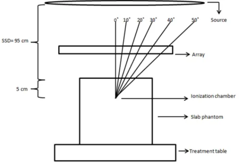
Materials and methods: Measurements were performed using an ion chamber placed in a slab phantom positioned at the linac isocenter for 6 MV, 10 MV, FFF 6 MV and FFF 10 MV photon beams. Measurements were performed with and without array above the phantom for 0˚, 10˚, 20˚, 40˚ and 50˚ beam angle for a True Beam STx linac, for 5 x 5 cm2 and 10 x 10 cm2 field size beams to evaluate the attenuation of the array. Results and discussion: Attenuation measured values were up to 3 %. Angular dependence of the attenuation was observed. Attenuation values were between 1 % - 2 % with the exception of the 30o - 50o gantry angles which were up to 3,3 %.
Conclusion: Attenuation of treatment beam by the Calypso array may be within acceptable limits.
Keywords: Calypso, array, attenuation.
Introduction
Higher accuracy and reproducibility in radiotherapy has led to great development in imaging and monitoring systems. Megavoltage imaging has been used clinically for many years, and kV imagers have also been installed in linacs all over the world. Monitoring systems for tracking movement during treatment have been used to monitor
22 patient surface – e.g. infrared tracking of external markers or virtual view of the patient surface – or the tumor movement – e.g. fluoroscopy (1-11).
The Calypso 4D Localization System is a monitoring system that gives the possibility to track the tumor during treatment, with no additional ionizing radiation delivered, a great advantage when compared to other systems available (12).
This system has five components: Beacon transponders, the console, the array, the optical localization subsystem and the monitoring station (13). The array consists of 4 sources and 32 receiver coils. An oscillating signal (25 Hz) through the source coil generates resonance in the transponders. When this signal is turned off, the transponders emit electromagnetic signals, which are detected by the receiver coils in the array, thereby localizing their positions relative to the array. Meanwhile, the in-room infrared camera system tracks the array relative to the isocenter (14).
To monitor the patient continuously an array is used. This array is positioned above the patient during the treatment (13, 15). The internal structure of the array panel contains optical targets, source coils and sensors (13).
Although the array lies between the patient and the beam, it is not included in the dose calculation of the treatment planning system.
Zou et al. studied the array attenuation effect for the regular energies 6 MV and 15 MV photon beams for various gantry angles – and concluded that the dose difference due to the placement of Calypso array was clinically insignificant to the treatment (16). In our institute the calypso system is mainly used in the irradiation of free flattening filter (FFF) beams. Given that the removal of the flattening filter lowers the mean energy of the beam we propose to study, for various gantry angles, the attenuation effect of the array for FFF 6 and FFF 10 MV photon beams.
Materials and methods
Transmission measurements were performed on a True Beam STx linear accelerator (Varian Medical Systems, Palo Alto, CA, USA) using a CC13 ionization chamber of 0,13 cm3 of sensitive volume (IBA Dosimetry, Germany) connected to a Dose 1 electrometer (IBA Dosimetry, Germany). Corrections for temperature and pressure were applied.
23 The ionization chamber was inserted in a slab phantom and positioned in the isocenter at 5 cm depth. See Figure 1.
The array was positioned above the phantom in the (0, 0, 0) position indicated by Calypso software system, in the same way it is positioned above the patient during treatment (See Figure 1).
Figure 1. Gantry angle measurements acquisition scheme
Measurements were performed for regular 6- and 10 MV and FFF 6- and FFF 10 MV energies, for both 5 x 5 and 10 x 10 cm2 square field sizes. The readings were obtained in six different gantry angles: 0 ˚, 10˚, 20˚, 30˚, 40˚ and 50˚. For each measurement, 200 monitor units (MU) were delivered at a dose rate of 600 MU/min for regular beam energies and 800 MU/min for FFF energies.
Measures were performed with and without the array in the beam path. Each measurement was repeated five times. The transmission measurements were registered in a table. The attenuation was calculated according to the formula:
attenuation % 1 measurement with array
measurement without array ∗ 100
The attenuation calculated values were registered and analyzed. Mean and standard deviation were calculated.
24 Results and discussion
The attenuation values measured were higher for 5 x 5 cm2 fields than for 10 x 10 cm2 fields for all energies and for the same measurement conditions. Therefore, the data shows that the beam attenuation is field size dependent. This dependency was not calculated. Field size dependency has been previously reported in other devices attenuation studies, although this dependency was also not quantifiable in those reports (17-19).
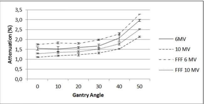
These studies usually also report an angular dependence on the attenuation of the beam by devices. A second degree polynomial fit was applied to the attenuation curves. For the 5 x 5 cm2 field size curves, the r2 value for 6 MV, 10 MV, FFF 6 MV and FFF 10 MV of 0,97; 0,95; 0,95 and 0,96, respectively. For 10 x 10 cm2 field size curves, the r2 value was 0,96; 0,98; 0,97 and 0,98, for the same energies respectively. Therefore, there is a tendency for higher attenuation values as the gantry angle increases, as it is shown in Figures 2 and 3.
25 Figure 3. Attenuation by Calypso array of 10 x 10 cm2 field size beams.
Only one measurement showed a standard deviation of 0,2 %. All the other points measured showed 0,0 % or 0,1% standard deviation. Measurements can be considered precise.
The array attenuation calculated values are comparable to attenuation values presented previously. Zou et al. reported that the attenuation on the array was about 2 % - 3 % for both 6 and 15 MV energies, for 1 x 1 cm2 field size beams at gantry angles between 0˚ - 40˚. The calculated attenuation slowly increased above these values for angles around 50˚ - 60˚ (16).
Here the calculated attenuation values were between 1 % - 2 % for gantry angles 0˚, 10˚, 20˚ and 30˚, for both field sizes for all energy beams. Acquisitions at 40˚ and 50˚ gantry angles showed higher attenuation values. The higher attenuation calculated value was 3,3% for a 5 x 5 cm2 field for a FFF 6 MV beam (gantry angle: 50˚), and 3,1 % for a 10 x 10 cm2 field of the same energy beam, at the same gantry angle.
A limitation of this study is that point measurements were performed and because the FFF energy beams are not flat by definition, positioning accuracy of the ionization chamber can be challenging. Furthermore, the array is also inhomogeneous, as it contains source coils, sensors and infrared targets. A 2D EPID detector could be used to assess that, however it has to be compatible with the use of FFF beams.
26 Conclusion
The behavior of the array attenuation curves is important to study due to its inhomogeneous structure.
Dose attenuations were measured to be within 1 % - 2 % with the exception of the 30o - 50o gantry angles which were up to 3,3%. The results indicate that the dose attenuation of the Calypso array may be within acceptable limits.
Future work should assess the Calypso attenuation of radiotherapy treatment beams with more detail.
References
1. Schweikard A, Shiomi H, Adler J. Respiration tracking in radiosurgery. Med Phys 2004;31:2738–2741.
2. Meeks SL, Bova FJ, Wagner TH, et al. Image localization for frameless stereotactic radiotherapy. Int J Radiat Oncol Biol Phys. 2000;46:1291–1299. 3. Bova FJ, Meeks SL, Friedman WA, et al. Optic-guided stereotactic
radiotherapy. Med Dosim. 1998;23:221–228.
4. Roberts DW, Strohbein JW, Hatch JF. A frameless stereotactic computerized tomographic imaging and the operating microscope. J Neurosurg. 1986;65:545–549.
5. Watanabe E, Mayanagi Y, Kosugi Y, et al. Open surgery assisted by the articulated, sensitive arm. Neurosurgery. 1991;28:792–800.
6. Suess O, Suess S, Mularksi S, et al. Study on the clinical application of pulsed DC magnetic technology for tracking of intraoperative head motion during frameless stereotaxy. Head Face Med. 2006;2:10.
7. Keall PJ, Todor AD, Vedam SS, et al. On the use of EPID-based implanted marker tracking for 4D radiotherapy. Med Phys. 2004; 31:3492–3499.
8. Meeks SL, Buatti JM, Bouchet LG, et al. Ultrasound-guided extracranial radiosurgery: Technique and application. Int J Radiat Oncol Biol Phys 2003;55:1092–1101.
9. Tome WA, Meeks SL, Orton NP, et al. Commissioning and quality assurance of an optically guided three-dimensional ultrasound target localization system for radiotherapy. Med Phys. 2002;29:1781-1788.
10. Sharp GC, Jiang SB, Shimizu S, et al. Tracking errors in a prototype real-time tumor tracking system. Phys Med Biol 2004;49: 5347-5356.
27 11. Stieler F, Wenz F, Shi M, Lohr F. A novel surface imaging system for patient positioning and surveillance during radiotherapy: a phantom study and clinical evaluation. Strahlenther Onkol. 2013; 189:938-944.
12. Litzenberg DW, Willoughby TR, Balter JM, et al. Positional Stability of Electromagnetic Transponders Used for Prostate Localization and Continuous, Real-time Tracking System and On-board Kilovoltage Imaging System. Int. J. Radiation Oncology Biol. Phys., 2007;68(4):1199-1206.
13. Quigley MM, Mate TP, Sylvester JE. Prostate tumor alignment and continuous, real-time adaptive radiation therapy using electromagnetic fiducials: Clinical and cost-utility analyses. Urologic Oncology: Seminars and Original Investigations. 2009; 27:473-482.
14. Santanam L, Malinowski K, Hubenshmidt J, et al. Fiducial-Based Translational Localization Accuracy of Electromagnetic Tracking System and On-Board Kilovoltage Imaging System. Int. J. Radiation Oncology Biol. Phys. 2008; 70(3)892-899.
15. Li HS, Chetty IJ, Enke CH, et al. Dosimetric Consequences of Intrafraction Prostate Motion. Int. J. Radiation Oncology Biol. Phys. 2008; 71(3):801–812. 16. Zou, W, Betancourt R, Yin L, Metz J, Avery S, Kassaee A. Effects on the
photon beam from an electromagnetic array used for patient localization and tumor tracking. Journal of Applied Clinical Medical Physics, 2013; 14(3):72-80. 17. Myint K, Niedbala M, Wilkins D, Gerig LH. Investigating treatment dose error
due to beam attenuation by a carbon fiber tabletop, J Appl Clin Med Phys. 2006;7(3):21–27.
18. Njeh CF, Raines TW, Saunders MW. Determination of the photon beam attenuation by the BrainLAB imaging couch: angular and field size dependence. Journal of Applied Clinical Medical Physics. 2009; 10(3): 16-27.
19. Seppälä JKH, Kulmala JAJ. Increased beam attenuation and surface dose by different couch inserts of treatment tables used in megavoltage radiotherapy. Journal of Applied Clinical Medical Physics, 2011; 12(4): 15-23.
31
Attenuation Study of Three Different Radiotherapy Tabletops
Célia Silva a1a2, Dalila Mateus a1, Sandra Vieira, PhD a1, Margarida Eiras, PhD a2, Carlo Greco, MD a1a1 Centro Clínico Fundação Champalimaud, Lisboa, Portugal a2 Escola Superior de Tecnologias da Saúde de Lisboa, Portugal
Abstract
Introduction: Our clinic acquired a Calypso 4D Localization System where electromagnetic (EM) frequencies to detect implanted transponders in the patient are used. Carbon fiber is an electrical conductive material which interferes with EM frequencies. In order to be able to use the Calypso System the carbon fiber tabletop in the treatment room must be replaced. It is our goal to determine the attenuation of the new tabletops.
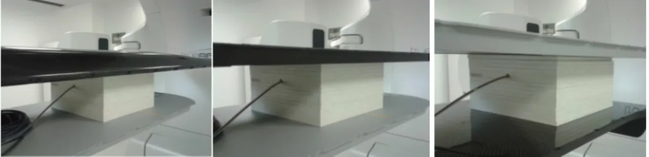
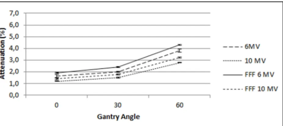
Materials and Methods: Transmission measurements were performed using an ionization chamber inserted in a slab phantom positioned at the isocenter for 6 MV, 10 MV, 6FFF MV and 10FFF MV photon beams for 0˚, 30˚ and 60˚ beam angles for 5 x 5 cm2 and 10 x 10 cm2 field size beams. The attenuation was calculated for each measurement.
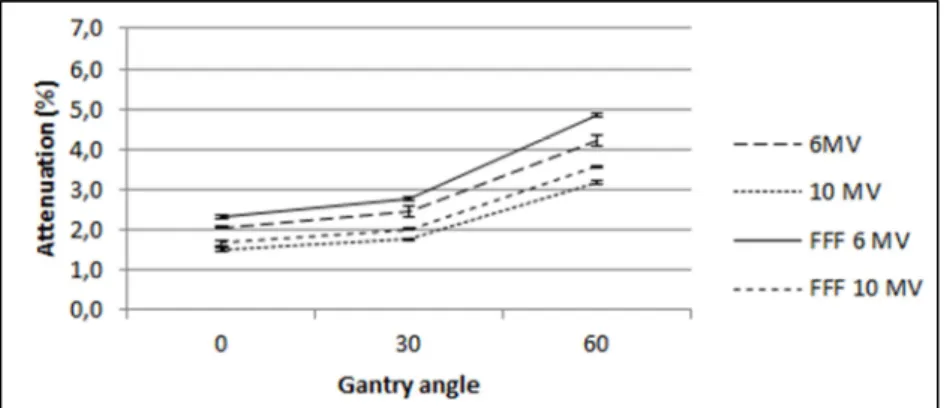
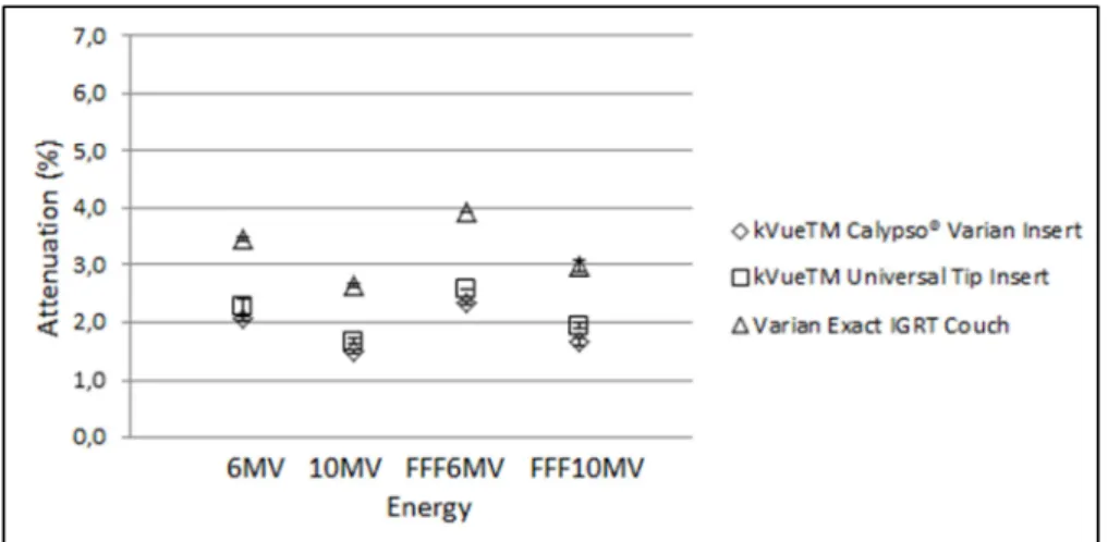
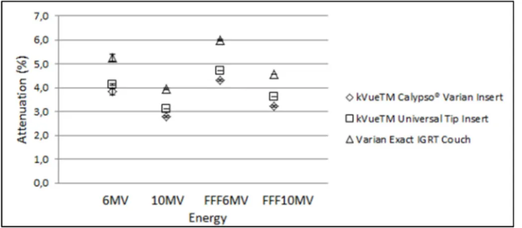
Results: At 0o incidence on the Exact IGRT Couch, the measured attenuation for 10 x 10 cm2 was 2,8% and 2,1% for 6 MV and 10 MV beams, respectively. For the same field size was measured 3,3% and 2,6% attenuation for 6FFF MV and 10FFF MV beams, respectively. At the same incidence and regarding the other tabletops, the calculated attenuation is lower. For 10 x 10 cm2 field there is 2,0%, 1,4%, 2,1% and 2,6% attenuation for 6MV, 10 MV, 6FFF MV and 10FFF MV energy beams on the kVueTM Universal Couch. For the KvueTM Calypso ®Couch 10 x 10 cm2 irradiation field, the measurements were respectively 1,6%, 1,3%, 1,9% and 1,5%. This tendency is observed for all gantry angles.
Discussion: The attenuation outputs were higher for the Varian Exact IGRT Couch when compared to the kVue tabletops. kVueTM Calypso® Varian tabletop showed smaller mean attenuation of the beams than kVueTM Universal Tip Insert for all measurements.
32 Conclusions: There was no loss in treatment quality administration due to beam attenuation in the tabletop when tabletops were exchanged because of Calypso system integration. There is no need to change between kVue tabletops whenever there is a regular treatment or a Calypso System guided treatment.
Keywords: Calypso, tabletop attenuation, carbon fiber, kevlar
Introduction
The main goal in radiotherapy is to deliver the prescribed dose to the target volume affecting the surrounding healthy tissues as less as possible (1-5). In order to achieve the later, radiation is delivered to the patient from different angles, while the patient is lying on the treatment table. When posterior and posterior oblique treatment beams pass through the treatment couch attenuation of the photon beams occurs (6). Radiotherapy treatment couches are usually made of carbon fiber. Carbon fiber is a polymer like component (7), widely used in radiotherapy treatments due to its high mechanical strength and rigidity, low specific density, extremely light, and regularly considered radiotranslucent (8-11). Moreover, artifacts in the images acquired in clinical routine for setup correction are avoided if carbon fiber components are used
(12, 13).
The attenuation of various carbon fiber couches has already been reported by other authors (10, 14-16). Some treatment planning systems have the possibility to include the attenuation factor for the tabletop used for the treatment.
A system for tracking the tumor has been approved for radiotherapy treatment: Calypso 4D Localization System. It consists of a magnetic array positioned above the patient during treatment that continuously detects the position of the transponders that were previously placed inside the patient, in/by the tumor. Three infrared cameras in the room detect the position of the array relative to the isocenter (17).
For the beacons detection to be accurate, it is necessary to guaranty some requirements. beacons have to be in the array’s volume detection, there is a maximum distance between the treatment isocenter and the beacons, and also, no electric conductive materials are allowed in the array’s volume detection. This last item may prevent patients with certain metallic prosthesis to be treated with Calypso.
Besides metal, carbon fiber compatibility with Calypso system is also an issue. It is known that carbon fiber is an electrical conductive material and it interferes with EM
33 frequencies detection (7, 12). If the treatment couch has a carbon fiber tabletop, it has to be replaced by a Calypso system compatible tabletop. As compared to other light-weight materials, such as carbon fiber, Kevlar is less conductive and thus tends to cause less distortion in the electromagnetic field (7, 18).
In our institute a Calypso 4D Localization System was acquired. The previous treatment couch had to be changed according to Calypso system guidelines when calypso was installed. The Varian Exact IGRT Couch (no rails) was replaced by a tabletop system with rails support and two different tabletops – kVueTM Universal Tip Insert (carbon fiber) and kVueTM Calypso ® Varian Insert (Kevlar).
In the current article we report on the attenuation effect of the above mentioned three tabletops for regular 6- and 10-MV photon beams and also Flattening Filter Free (FFF) 6- and 10 MV photon beams produced by a Varian True Beam STx machine, for various gantry angles. It is our goal to (1) determine the attenuation of the new treatment tabletops and (2) to verify if it is adequate not to switch between kVueTM Calypso® Varian and kVueTM Universal Tip tabletops according to the use of calypso system or not, respectively.
Materials and Methods
Measurements were performed on a True Beam STx linear accelerator (Varian Medical Systems, Palo Alto, CA, USA) equipped with regular 6 MV and 10 MV and also FFF6 MV and FFF 10 MV energies.
Three tabletops were studied: Varian Exact IGRT tabletop (carbon fiber), kVueTM Universal Tip Insert (carbon fiber) and kVueTM Calypso ® Varian Insert (kevlar).
Transmission measurements were performed with a CC13 ionization chamber of 0,13 cm3 of sensitive volume (IBA Dosimetry, Germany) connected to a Dose 1 electrometer (IBA Dosimetry, Germany). Corrections for temperature and pressure were applied. The ionization chamber was positioned aligned to the isocenter inserted in a slab phantom at 5 cm depth. The source-detector distance was 100 cm.
Measurements were done for the four referred energies, for both 5 x 5 cm2 and 10 x 10 cm2 square field sizes. The readings were obtained in three different gantry angles: 0o, 30o and 60o. For every measurement 200 MU were delivered at a dose rate of 600 MU/min for regular beam energies and 800 MU/min for FFF energies.