Coordinating distributed autonomous agents with
a real-time database: The CAMBADA project
1L. Almeida1, F. Santos2, T. Facchinetti3, P. Pedreiras1, V. Silva4, L. Seabra Lopes1 1
LSE-IEETA/DET, University of Aveiro, Portugal {lda,pedreiras,lsl}@det.ua.pt 2
DEE-ISEC, Polytechnic Institute of Coimbra, Portugal [email protected]
3
DIS, University of Pavia, Italy [email protected] 4
ESTGA, University of Aveiro, Portugal [email protected]
Abstract. Interest on using mobile autonomous agents has been growing, recently, due to their capacity to cooperate for diverse purposes, from rescue to demining and security. However, such cooperation requires the exchange of state data that is time sensitive and thus, applications should be aware of data temporal coherency. In this paper we describe the architecture of the agents that constitute the CAMBADA robotic soccer team developed at the University of Aveiro, Portugal. This architecture is built around a real-time database that is partially replicated in all team members and contains both local and remote state variables. The temporal coherency of the data is enforced by an adequate management system that refreshes each database item transparently at a rate specified by the application. The application software accesses the state variables of all agents with local operations, only, delivering both value and temporal coherency.
1 Introduction
Coordinating several autonomous mobile robotic agents in order to achieve a common goal is currently a topic of intense research [14,7]. This problem can be found in many robotic applications, either for military or civil purposes, such as search and rescue in catastrophic situations, demining or maneuvers in contaminated areas.
The technical problem of building an infrastructure to support the perception integration for a team of robots and subsequent coordinated action is common to the above applications. One recent initiative to promote research in this field is RoboCup [7] where several autonomous robots have to play football together as a team, to beat the opponent. We believe that researching ways to solve the perception integration problem in RoboCup is also very relevant to real-world applications.
Currently, the requirements posed on such teams of autonomous robotic agents have evolved in two directions. On one hand, robots must move faster and with accurate trajectories to close the gap with the dynamics of the processes they interact
1
CAMBADA – Cooperative Autonomous Mobile roBots with Advanced Distributed Architecture. Project supported by the Portuguese Government under contract FCT-POSI/ROBO/43908/2002, and partially funded by FEDER).
with, e.g., a ball can move very fast. On the other hand, robots must interact more in order to develop coordinated actions more efficiently, e.g., only the robot closer to the ball should try to get it while other robots should move to appropriate positions. The former requirement demands for tight closed-loop motion control while the latter demands for an appropriate communication system that allows building a global information base to support cooperation. Both cases are subject to time constraints that must be met for adequate performance.
In this paper we describe the architecture of the robotic agents that constitute the CAMBADA middle-size robotic soccer team of the University of Aveiro, Portugal, which is well suited to support the requirements expressed above. The hardware architecture follows the biomorphic paradigm while the software architecture is based on a real-time database, i.e., a structure containing the current values of relevant local state variables together with local images of (remote) state variables of other cooperating agents. The temporal coherency, i.e., degree of timeliness, of the data is enforced by an adequate management system that refreshes each database item at a rate specified by the application.
This architecture is innovative in what concerns the mix of using replicated databases together with temporal coherency information and a management system that uses real-time communication techniques to schedule the traffic and enforce timely updates of the database items, dynamically adapting to the conditions of the communication channel. This paper is structured as follows: The following section discusses the generic computing and communications architecture of CAMBADA. Section 3 describes the high-level coordination system, focusing on the real-time database (RTDB). Section 4 describes the communication protocol among agents. Section 5 describes the communication requirements of the current implementation and section 6 concludes the paper.
2
Computing and communications architecture
The computing architecture of the robotic agents follows the biomorphic paradigm [10], being centered on a main processing unit (the brain) that is responsible for higher-level behaviors coordination. This main processing unit handles external communication with other agents and has high bandwidth sensors, typically vision, directly attached to it. Finally, this unit receives low bandwidth sensing information and sends actuating commands to control the robot attitude by means of a distributed low-level sensing/actuating system (the nervous system). This biomorphic architecture is depicted in Fig. 1.
The main processing unit is currently implemented on a laptop that delivers sufficient computing power while offering standard interfaces to connect the other systems, namely USB. The wireless interface is either built-in or added as a PCMCIA card. The laptop runs the Linux operating system over the RTAI (Real-Time Applications Interface [11]) kernel, which provides timeliness support, namely for time-stamping, periodic transmissions and task temporal synchronization. This approach follows a similar paradigm as the Timely Computing Base proposed in [12].
The agents that constitute the team communicate with each other by means of an IEEE 802.11b wireless network as depicted in Fig. 2. The communication is managed, i.e., using a base station, and it is constrained to using a single channel,
shared by both teams in each game. In order to improve the timeliness of the communications, our team uses a further transmission control protocol that minimizes collisions of transmissions within the team. An important feature is that the communication follows the producer-consumer co-operation model, according to which each robot regularly broadcasts, i.e. produces, its own data while the remaining ones receive, i.e. consume, such data and update their local structures. Beyond the robotic agents, there is also a coaching and monitoring station connected to the team that allows following the evolution of the robots status on-line and issuing high level team coordination commands.
Fig.1. The biomorphic architecture of the CAMBADA robotic agents
The low-level sensing/actuating system follows the fine-grain distributed model [8] where most of the elementary functions, e.g. basic reactive behaviors and closed-loop control of complex actuators, are encapsulated in small microcontroller-based nodes, interconnected by means of a network. This architecture, which is typical for example in the automotive industry, favors important properties such as scalability, to allow the future addition of nodes with new functionalities, composability, to allow building a complex system by putting together well defined subsystems, and dependability, by using nodes to ease the definition of error-containment regions.
Fig. 2. Global team communications architecture, with the robotic agents and a monitoring station interconnected by means of an IEEE 802.11 wireless network
This architecture relies strongly on the network, which must support real-time communication. For this purpose, Controller Area Network (CAN) [2] has been chosen, which is a real-time fieldbus typical in distributed embedded systems. This network is complemented with a higher-level transmission control protocol to enhance its real-time performance, composability and fault-tolerance, namely the FTT-CAN protocol (Flexible Time-Triggered communication over CAN) [1]. The use
Main Processor External communication (IEEE 802.11b) High bandwidth sensors Distributed sensing/actuating system Coordination layer Low-level control layer R1 R3 R2 IEEE 802.11 Network
of FTT-CAN has the advantage of combining time-triggered communication, which is adequate for closed-loop control functions, with operational flexibility supporting on-line reconfiguration and thus higher maintainability and capacity to cope with evolving requirements.
Currently, the interconnection between CAN and the laptop is carried out by means of a gateway, either through a serial port operating at 115Kbaud or through a serial-to-USB adapter. The nodes of the system are based on an 8-bit microcontroller from Microchip, namely the PIC 18F485 [9].
3
RTBD - The real-time database
Similarly to other teams [4,6,13], our team software architecture emphasizes cooperative sensing as a key capability to support the behavioral and decision-making processes in the robotic players. A common technique to achieve cooperative sensing is by means of a blackboard [5], which is a database where each agent publishes the information that is generated internally and that maybe requested by others. However, typical implementations of this technique seldom account for the temporal validity (coherence) of the contained information with adequate accuracy, since the timing information delivered by general-purpose operating systems such as Linux is rather coarse. This is a problem when robots move fast (e.g. above 1m/s) because their state information degrades faster, too, and temporal validity of state data becomes of the same order of magnitude, or lower, than the operating system timing accuracy.
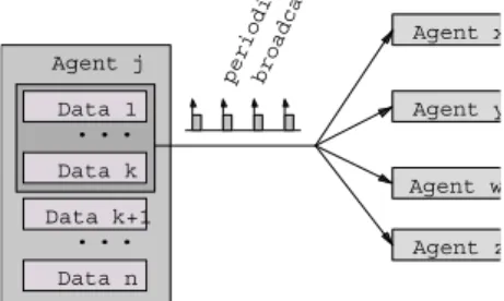
Another problem of typical implementations is that they are based on the client-server model and thus, when a robot needs a datum, it has to communicate with the server holding the blackboard, introducing an undesirable delay. To avoid this delay, we use two features: firstly, the dissemination of the local state data is carried out using broadcasts (Fig. 3), according to the producer-consumer cooperation model, as referred in the previous section; secondly, we use a replicated blackboard, so that it can be readily accessed with local operations, only.
broadc a period i Agent z Agent w Agent y Agent x Agent j Data 1 Data k Data k+1 Data n
...
...
Fig. 3. Each agent broadcasts periodically its subset of state data that might be required by other agents
We call this replicated blackboard the Real-time Data Base (RTDB), similarly to the concept presented in [8], which holds the state data of the local agent together with local images of the state data of the other team members. A specialized communication system manages the refreshing of the data in an automatic way by triggering the respective transactions at an adequate rate. This is carried out under
control of the RTAI kernel, guaranteeing that the transmission instants are respected within small tolerances, contributing to achieve better close-loop control of the robots.
Generally, the information within the RTDB holds the absolute positions and postures of all players, as well as the position of the ball, goal areas and corners in global coordinates. This approach allows a robot to easily use the other robots sensing capabilities to complement its own. For example, if a robot temporarily loses track of the ball, it might use the position of the ball as detected by another robot.
3.1 RTDB implementation
The RTDB is implemented over a block of shared memory, between Linux and RTAI. It contains two main areas: a private area for local information, only, i.e., which is not to be broadcast to other robots; and a shared area with global information. The shared area is further divided into a number of areas, one corresponding to each agent in the team. One of the areas is written by the agent itself and broadcast to the others while the remaining areas are used to store the information received from the other agents.
The allocation of shared memory is carried out by means of a specific function call,
DB_init(), called once by every Linux process that needs access to the RTDB. The actual allocation is executed within RTAI by the first such call, only. Subsequent calls just return the shared memory block handler and increment a process count. Conversely, the memory space used by the RTDB is freed using the function call
DB_free() that decreases the process count and, when zero, releases the shared memory block.
The RTDB is accessed concurrently from Linux processes that capture and process images and implement complex behaviors, and from RTAI tasks that manage the communication both with the lower-level control layer (through the CAN gateway) and with the other agents (through the wireless interface). The Linux processes access the RTDB with local non-blocking function calls, DB_put() and DB_get() that allow writing and reading records, respectively (Fig. 4 shows the prototypes of the RTDB related function calls). DB_get() further requires the specification of the agent from which the item to be read belongs to, in order to identify the respective area in the database.
int DB_init (void); void DB_free (void);
void DB_put (int _id, void *_value);
int DB_get (int _agent, int _id, void *_value). Fig. 4. The RTDB related function calls
3.2 Synchronization of concurrent accesses
A specific synchronization mechanism allows enforcing data consistency during concurrent accesses among Linux processes and between these and RTAI tasks. This mechanism uses two features. Firstly, the DB_put() primitive sends all RTDB update requests to RTAI where they are handled by only one real-time task,
DB_writer, which actually writes in the database. This same task also handles the
RTDB updates arriving from the lower-level control layer. This ensures atomic access during local write operations. Notice that remote write operations with the
information received from other agents are carried out by another real-time task,
DB_IO, which is not concurrent with DB_writer because they write in different areas.
Secondly, there is a control field in each record that allows knowing whether an item was updated since it was last read. This field is set by any write operation on that item and reset within DB_get() just before reading the information. DB_get() also checks the status of that control field after retrieving the data and thus, if the field changes status in between, then there was a write operation that corrupted the read operation and this one is repeated. This ensures consistent data retrieval.
The software architecture of the main processing unit that holds the RTDB is illustrated in Fig. 5. The actual wireless communication is handled within Linux by a high-priority task, with SCHED_FIFO scheduler, due to unavailability of RTAI device drivers for certain wireless cards.
from ot agents agents to other RtDB Local Inter-agent communication communication Task LINUX RTAI Task DB writer DB I/O
Fig. 5. The software architecture of the main processing unit, highlighting the RTDB, the Linux processes and the related real-time tasks
3.3 Internal structure of the RTDB
The RTDB is organized in a set of records plus a set of related data blocks. The records contain the fields referred in Fig. 6, i.e., an identifier, a pointer to the respective data block, the size of that block, a timestamp of the last update instant, the update period and a control field for synchronization purposes as referred previously.
typedef struct _TRec {
int id; // entity identification unsigned long int offset;
unsigned long int size; unsigned long int time; int period;
unsigned char write_control; } Trec;
Fig. 6. The fields of the generic RTDB record
For the sake of regularity, all the records are stored sequentially in the initial part of the RTDB, followed by all the respective data blocks (Fig. 7).
Data k
Data 1 Data k+1 Data n
Offset k Offset 1 Offset k+1 Offset n
Shared structures Local structures
...
...
...
...
. ID k Offset k...
ID k+1 Offset k+1...
ID n Offset n...
Offset 1...
ID 1Fig. 7. The internal organization of the RTDB in records and associated data blocks
4
Communication among agents
As referred in section 2, agents communicate using an IEEE 802.11 network, sharing a single channel with the opposing team and using managed communication (through the access point). This raises several difficulties because the access to the channel cannot be controlled [3] and the available bandwidth is roughly divided by 2.
Therefore, the only alternative left for each team is to adapt to the current channel conditions and reduce access collisions among team members. This is achieved using an adaptive TDMA transmission control, with a predefined round period called team
update period (Ttup) that sets the responsiveness of the global communication.
Within such round, there is one single slot allocated to each team member so that all slots in the round are separated as much as possible.
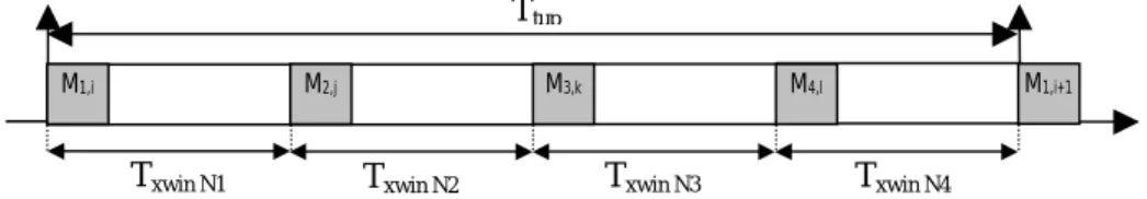
The transmissions generated by each agent are scheduled within DB_IO, according to the production periods specified in the RTDB records. Currently a rate-monotonic scheduler is used. When the respective TDMA slot comes, all currently scheduled transmissions are piggybacked on one single 802.11 frame and sent to the channel. The required synchronization is based on the reception of the frames sent by the other robots during Ttup. With the reception instants of those frames, their lengths and the target inter-slot period Txwin it is possible to generate the next transmission instant. If no frame is received during a round, then the next frame is sent Ttup after the previous one. If these delays affect all TDMA frames in a round, then the whole round is delayed from then on, thus its adaptive nature. Fig. 8 depicts one TDMA round indicating the slots allocated to each robot.
Fig. 8. TDMA transmission control of wireless communication within the team
Txwin N1 Txwin N2 Txwin N3 Txwin N4
Ttup
Carrying out the bandwidth allocation in this way contributes to increase the protocol resilience since the messages are transmitted as far apart as possible and thus being more tolerant to deviations either caused by temporary loss of communication or by interference from other traffic.
5 Communication
requirements
In this section we present the effective communication requirements of the current CAMBADA robots implementation, both concerning the inter-robots communication and the intra-robots communication with the distributed sensing and actuation system.
5.1 Inter-robots communication requirements
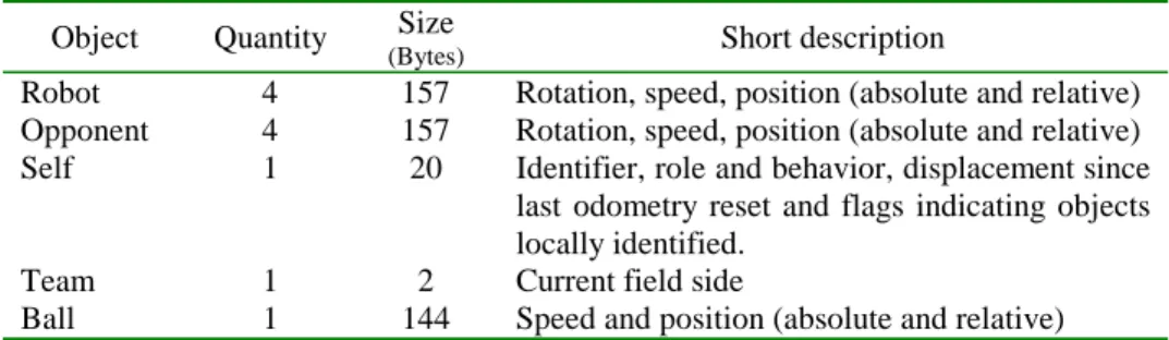
The inter-robots communication is directly deduced from the contents of the RTDB shared areas. Particularly, each robot has to transmit its own area which contents are show in Table 1. When all items are ready for transmission simultaneously, the total data to be transmitted amounts to 1420 bytes. At 11Mbps, this takes slightly less than 1.2ms, a time that is doubled because of the managed communication (requiring re-transmission by the access point). Therefore, the total time per-transaction is upper-bounded to 2.4ms.
Moreover, a value of 100ms for Ttup, the TDMA round period, seems adequate for refreshing the remote images of the state variables, since these are not used within high-speed closed-loop control. This value also establishes a good compromise in terms of used bandwidth. In fact, considering 4 team members, yields Txwin=25ms and thus, the bandwidth taken to broadcast the robots state data is less than 10%. Table 1. State data of each robot, to be shared with the remaining team members
Object Quantity Size
(Bytes) Short description
Robot 4 157 Rotation, speed, position (absolute and relative) Opponent 4 157 Rotation, speed, position (absolute and relative) Self 1 20 Identifier, role and behavior, displacement since
last odometry reset and flags indicating objects locally identified.
Team 1 2 Current field side
Ball 1 144 Speed and position (absolute and relative)
5.2 Communication requirements of the lower-level control layer
The lower-level control layer is formed by the distributed sensing and actuating system interconnected to the main processing unit. This distributed system includes a set of nodes that are depicted in Fig. 9. The communication requirements at this level are shown in Table 2. As referred in section 2, this distributed system is based on a CAN network complemented with the FTT-CAN protocol. The former operates at 250Kbps and, according to this transmission rate and to the requirements in Table 2, the FTT-CAN protocol is configured with an Elementary Cycle (EC) 10ms long and a maximum Synchronous Window (LSW) of 28% the duration of the EC.
Fig. 9. The hardware architecture of the distributed sensing/actuating system
Moreover, an efficient use of the FTT-CAN protocol further requires the separation of the message streams in two sets, the synchronous set (SS) and the asynchronous set (AS). In this case, the SS is composed by messages {M1, M3.1-M3.3, M4.1, M4.2, M6.1, M6.2} while messages {M2, M5.1, M5.2, M7} belong to the AS.
Basically, M6 conveys movement vectors from the laptop to the node Pic-base. This node computes the individual set points for each motor (holonomic motion) and sends them to the motors via M1. These two messages, M6 and M1, support closed loop controlled motion of visually tracked items, e.g. the ball. Each motor sends its odometry readings to the Pic_Odom node, using M3. Finally, Pic_Odom estimates the robot position and reports it to the laptop using M4. M5 allows setting or resetting the robot position. Finally, M7 is used to actuate the ball kicker while M2 alerts the system that batteries charge is running low.
Table 2. Communication requirements of the lower-level control layer
ID Source Target Type Period/mit (ms) Size (B) Short description M1 Pic_base Motor[1:3] Periodic 30 6 Aggregate motor set points M2 Pic_base Laptop Sporadic 1000 2 Battery status
M3.1-M3.3 Motor[1:3] Pic_odom Periodic 10 3*3 Wheel encoder value
M4.1-M4.2 Pic_odom Laptop Periodic 50 7+4 Robot position (position + rotation) M5.1-M5.2 Laptop Pic_odom Sporadic 500 7+4 Set/reset robot position (position + rotation) M6.1-M6.2 Laptop Pic_base Periodic 30 7+4 Movement vector (rot+translational velocity)
M7 Laptop Pic_base Sporadic 1000 1 Kicker actuation
The analysis presented in [1] allows verifying that all time constraints are met, i.e., all the transmissions occur within the respective periods. The traffic scheduling policy followed by the FTT-Master is also rate-monotonic.
6 Conclusion
Cooperating robots is a field currently generating large interest in the research community. RoboCup is one example of an initiative developed to foster research in that area.
This paper described the computing and communication architecture of the CAMBADA middle-size robotic soccer team being developed at the University of Aveiro. This team has just participated in a few preliminary tournaments, with
USB Attitude controller Kick FTT Master Odom. manager Gateway
Global vision webcam
Mot 1 Odom 1 Mot 2 Odom
2
Mot 3 Odom 3
encouraging results, and it is expected to do participate at the next RoboCup event, in Lisbon, June/July of 2004. One of its distinguishing features is the smooth and effective motion control at relatively high speeds, e.g. when tracking and following the ball. This is achieved by means of a computing and communication architecture that includes real-time concerns from the bottom layers up to the coordination. In particular, the robots coordination is based on a replicated database, i.e., the Real-Time Data Base (RTDB) that includes local state variables together with images of remote ones. These images are updated transparently to the application software by means of an adequate real-time management system. Moreover, the RTDB is accessible to the application using a set of non-blocking primitives, thus yielding a fast data access.
The paper finishes with a brief analysis of the communication requirements of the current robots implementation.
References
1. Almeida, L., Pedreiras, P., Fonseca, J., “The FTT-CAN protocol: Why and How”. IEEE Transactions on Industrial Electronics, 49(6): 1189-1201. December 2002.
2. CAN Specification - Version 2.0. Robert Bosch GmbH. Stuttgard, 1991. 3. Decotignie, J.-D., et al., “Architecture for the Interconnection of Wireless
and Wireline Fieldbuses”, FeT'01 - IFAC Conf. on Fieldbus Technologies, Nancy. November, 2001.
4.
Dietl, M., J.-S. Gutmann and B. Nebel, “Cooperative Sensing in Dynamic Environments”, Proc. IROS 2001.5. Erman, L.D., F. Hayes-Roth, V.R. Lesser, D.R. Reddy, “The HERSAY-II Speech Understanding System: Integrating Knowledge to Resolve Uncertainty”, Computing Surveys, 12 (2), 1980.
6.
Jamzad, M., et al., “Basic Requirements for a Teamwork in Middle Size RoboCup”, Sharif-ARVAND team description. June 2001.7.
Kitano, K., M. Asada, Y. Kuniyoshi, I. Noda, E. Osawa, “RoboCup: The Robot World Cup Initiative”, Proc. of IJCAI-95 Workshop on Entertainmentand AI/Alife, Montreal. 1995.
8. Kopetz, H., “Real-Time Systems Design Principles for Distributed Embedded Applications”, Kluwer, 1997.
9. Microchip PIC18F458 datasheet, available at
http://ww1.microchip.com/downloads/en/DeviceDoc/41159c.pdf.
10. Proc. of the “NASA Workshop on Biomorphic Robotics”, Jet Propulsion Laboratory, California Institute of Technology. USA. August 14 - 16, 2000. 11. RTAI for Linux, available at http://www.aero.polimi.it/~rtai/
12. Veríssimo, P., Casimiro, A., “The Timely Computing Base Model and Architecture”, IEEE Transactions on Computers, 51(8), August 2002.