Miguel Ângelo Guimarães Sampaio
Wear of PEEK/Ti6Al4V systems under
micro-abrasion and linear sliding conditions
Miguel Ângelo Guimarães Sampaio
novembro de 2015
UMinho | 2015
W
ear of PEEK/T
i6Al4V sys
tems under micr
o-abr
novembro de 2015
Dissertação de Mestrado
Ciclo de Estudos Integrados Conducentes ao
Grau de Mestre em Engenharia
BiomédicaTrabalho efectuado sob a orientação do
Professor Doutor José Manuel Ramos Gomes
Professor Doutor Júlio César Matias de Souza
Miguel Ângelo Guimarães Sampaio
Wear of PEEK/Ti6Al4V systems under
v I dedicate this work to my Family and friends for all the support they gave me in the preparation of this work.
vii "The reason is the step, the increase of science the way, and the benefit of mankind is the end." Thomas Hobbes
ix
ACKNOWLEDGMENTS
First of all, I would like to thank my supervisor, Prof. José Manuel Ramos Gomes, for the support, dedication, flexibility, guidance, encouragement and scientific teachings throughout the project. It was a pleasure to work with you.
To my co-supervisor, Prof. Júlio Souza that despite to be far always offset this distance in the development of work. Thank you for all the transmitted knowledge and all the support.
To Prof. Filipe Samuel Silva, for the encouragement and support that you gave me throughout the project. To Profª. Mihaela Buciumeanu, for all the patience, flexibility, guidance, support, encouragement, sympathy, friendship and full availability for the experimental tests throughout this project.
To Sergio Carvalho for the excellent technical assistance and the constant words of support and encouragement. It was a pleasure working with you.
To Doctors Bruno Henriques and Óscar Carvalho for all the support and help with the hot-pressing machine.
To all my friends for supporting me at this stage, for being patient and listening to my concerns and discouragements. Thanks for all the help.
To my relatives for all the support, patience, understanding and help. Thank you for always being with me.
Finally, I want to thank especially my parents. All this would not be possible without your help and sacrifice. Always dedicated to giving me the best possible education and encouragement to follow front head high, never letting me down when I failed. Thanks for everything.
This work was supported by the Portuguese Foundation of Science and Technology through the projects: EXCL/EMS-TEC/0460/2012 and UID/EEA/04436/2013.
xi
ABSTRACT
In dentistry, prosthetic structures must be able to support masticatory loads combined with a high biocompatibility and wear resistance in the presence of a corrosive environment. Also, abrasive wear is inevitable at exposed tooth or restorative surfaces, during mastication and tooth brushing. Thus, this work is dedicated to the tribological characterization of PEEK/Ti6Al4V systems under reciprocating sliding conditions in presence of artificial saliva taking in consideration tribocorrosion aspects, being also considered the micro-abrasion wear behavior of the same systems in presence of slurry containing hydrated silica particles representative of the abrasive agent present on toothpastes.
In order to improve the simultaneous wear and corrosion response of highly biocompatible prosthetic structures, a veneering poly-ether-ether-ketone (PEEK) to Ti6Al4V substrate was assessed by tribocorrosion tests under conditions mimicking the oral environment. Samples were synthesized by hot--pressing the PEEK veneer onto Ti6Al4V cylinders (8 mm diameter and 4 mm thick). The tribocorrosion tests on Ti6Al4V or PEEK/Ti6Al4V samples were performed on a reciprocating ball-on-plate tribometer at 30 N normal load, 1 Hz and stroke length of 3 mm. The tests were carried out in artificial saliva at 37 ºC. Open circuit potential (OCP) was measured before, during and after reciprocating sliding tests.
Regarding the abrasive wear resistance, PEEK and Ti6Al4V samples were compared by under three-body abrasion conditions considering different hydrated silica content and applied loads. Micro-scale abrasion tests were performed at 60 rpm and on different normal loads (0.4, 0.8 or 1.2 N) for 600 revolutions of the testing ball using suspensions with different weight contents of hydrated silica.
In order to identify the dominant wear mechanisms the worn surfaces obtained from tribocorrosion and micro-abrasion tests were characterized by scanning electron microscope (SEM).
The tribocorrosion results revealed a lower wear rate on PEEK combined with a lower coefficient of friction (COF), when compared to Ti6Al4V. In fact, PEEK protected Ti6Al4V substrate against the corrosive environment and wear avoiding the release of metallic ions to the surrounding environment. The micro-abrasion results showed a higher volume loss on PEEK than that recorded on Ti6Al4V, when subjected to three-body abrasion tests involving hydrated silica suspensions. An increase of the volume loss was noted on both tested materials when the abrasive content or load was increased.
Wear of PEEK/Ti6Al4V systems under micro-abrasion and linear sliding conditions
xii
xiii
RESUMO
Na dentária, as próteses devem ser capazes de suportar cargas mastigatórias, combinadas com uma alta biocompatibilidade e resistência ao desgaste na presença de um ambiente corrosivo. O desgaste abrasivo é também inevitável no dente ou em superfícies restauradoras, durante a mastigação e escovagem dos dentes. Assim, este trabalho é dedicado à caracterização tribológica de sistemas PEEK/Ti6Al4V em condições de deslizamento linear alternativo na presença de saliva artificial tendo em consideração os aspetos de tribocorrosão, sendo também considerado o comportamento de desgaste por micro-abrasão no mesmo sistema, na presença de uma solução contendo partículas de sílica hidratada representativas de um agente abrasivo presente em pastas dos dentes.
De forma a melhorar a resistência ao desgaste e à corrosão de estruturas de próteses altamente biocompatíveis, foi considerado um recobrimento de poli-éter-éter-cetona (PEEK) sobre um substrato de Ti6Al4V o qual foi testado por tribocorrosão, em condições que procuraram imitar o ambiente oral. As amostras foram sinterizadas a quente sendo que o recobrimento de PEEK foi processado sobre o substrato de Ti6Al4V (8 mm de diâmetro e 4 mm de altura). Os testes tribocorrosão em amostras de Ti6Al4V ou PEEK/Ti6Al4V foram realizados num tribómetro de esfera-placa, com movimento linear alternativa da placa, para uma carga normal de 30 N, 1 Hz de frequência de oscilação e 3 mm de comprimento de pista. Os testes foram realizados em saliva artificial a 37 °C. O potencial de circuito aberto (OCP) foi medido antes, durante e após testes de deslizamento.
Em relação à resistência ao desgaste abrasivo, foram comparadas amostras de PEEK e de Ti6Al4V, em testes de micro-abrasão, com diferentes concentrações de sílica hidratada e diferentes valores de carga aplicada. Os testes de micro-abrasão foram realizados a velocidade constante de rotação da esfera (60 rpm), para diferentes cargas (0.4, 0.8 ou 1.2 N) e durante 600 rotações, usando diferentes concentrações de sílica hidratada.
De forma a identificar os mecanismos de desgaste dominantes, as superfícies de degaste obtidas nos testes de tribocorrosão e de micro-abrasão foram caracterizadas por microscopia eletrónica de varrimento (SEM).
Wear of PEEK/Ti6Al4V systems under micro-abrasion and linear sliding conditions
xiv
Os resultados de tribocorrosão revelaram uma baixa taxa de desgaste do PEEK, combinada com um baixo coeficiente de atrito, comparado com o Ti6Al4V. De facto, o PEEK protege o Ti6Al4V contra o ambiente corrosivo, evitando a libertação de iões metálicos para os tecidos. Os resultados de micro -abrasão mostram uma maior perda de volume de desgaste do PEEK do que o registado no Ti6Al4V, quando sujeito a abrasão a três corpos promovida por partículas de sílica hidratada. O aumento do volume de desgaste é notado nos dois materiais quando a concentração do abrasivo ou a carga aplicada aumenta.
xv
TABLE OF CONTENTS
ACKNOWLEDGMENTS...ix ABSTRACT ...xi RESUMO ... xiii TABLE OF CONTENTS ... xvLIST OF FIGURES ... xvii
LIST OF TABLES... xix
LIST OF ABBREVIATIONS ... xxi
LIST OF SYMBOLS ... xxiii
1. INTRODUCTION ... 3
1.1. Motivation of the study ... 3
1.2. Scope and aim of the thesis ... 4
1.3. Structure of the thesis ... 4
1.4. References ... 6
2. STATE OF THE ART ... 11
2.1. Concepts of Tribology ... 11
2.1.1. Definition and importance of Tribology ... 11
2.1.2. Contact between surfaces ... 13
2.1.3. Friction ... 14
2.1.4. Wear ... 16
2.1.5. Lubrication ... 21
2.2. Biotribology in the oral cavity ... 23
2.3. Prostheses and dental implants ... 25
2.3.1. Dental implants... 25
2.3.2. Biomedical requirements... 27
2.3.3. Materials used in dental implants... 27
2.4. References ... 30
3. TRIBOCORROSION BEHAVIOR OF VENEERING BIOMEDICAL PEEK TO TI6AL4V STRUCTURES... 39
Abstract ... 39
Wear of PEEK/Ti6Al4V systems under micro-abrasion and linear sliding conditions
xvi
3.2. Materials and methods... 42
3.2.1. Preparation of Ti6Al4V substrates ... 42
3.2.2. Veneering procedure ... 43
3.2.3. Tribocorrosion tests ... 44
3.2.4. Microstructural characterization... 46
3.3. Results and discussion ... 46
3.3.1. Tribocorrosion measurements ... 46
3.3.2. Morphologic aspects of test sample surfaces after sliding ... 50
3.4. Conclusions... 52
Acknowledgements ... 52
References... 53
4. A COMPARATIVE STUDY BETWEEN MICRO-SCALE ABRASION WEAR OF PEEK AND TI6AL4V CONCERNING DENTAL APPLICATIONS ... 59
Abstract... 59
4.1. Introduction... 60
4.2. Materials and methods... 62
4.2.1. Preparation of test samples ... 62
4.2.2. Details on micro-scale abrasion tests ... 63
4.2.3. Volume loss ... 63
4.2.4. Microstructural characterization... 64
4.3. Results and discussion ... 64
4.3.1. Micro-scale abrasion wear measurements ... 64
4.3.2. Wear scar morphology ... 66
4.4. Conclusions... 70
Acknowledgements ... 71
References... 71
5. GENERAL DISCUSSION ... 77
5.1. Corrosion measurements... 77
5.2. Reciprocating sliding wear of PEEK veneering to Ti6Al4V samples ... 78
5.3. Abrasive wear of PEEK veneering to Ti6Al4V ... 79
5.4. References... 80
6. CONCLUSIONS AND SUGESTIONS FOR FUTURE WORK ... 85
6.1. Conclusions... 85
xvii
LIST OF FIGURES
Figure 1.1 - Flowchart of the evolution of the thesis... 5
Figure 2.1 - Ancestors moving a statue with water and animal-fat lubrication[3] ... 12
Figure 2.2 – Importance of Tribology in very distinct situations [4]. ... 13
Figure 2.3 - Interface of contact between two surfaces: a) apparent contact area, b) and c) real contact area. ... 14
Figure 2.4 - Adhesion wear phenomenon with transfer of material ... 17
Figure 2.5 – Schematic representation of the two and three body abrasive wear ... 18
Figure 2.6 - Different types of fatigue wear due cyclic applied loads ... 19
Figure 2.7 - Tribochemical wear effects with oxide films ... 20
Figure 2.8 - Tribometer for friction and wear tests (Bruker, USA), courtesy of the Tribology Laboratory, UMinho ... 21
Figure 2.9 - Micro-abrasion machine (Plint TE66, UK), courtesy of the Tribology Laboratory, UMinho .. 21
Figure 2.10 - Different regimes of lubrication, adapted of [1] ... 21
Figure 2.11 - Variation of coefficient of friction with the specific film thickness (h/𝜎),... 23
Figure 2.12 - Erosion caused by refrigerant and attrition caused by bruxism [27] ... 24
Figure 2.13 - Difference of the constitution of natural and artificial tooth ... 26
Figure 2.14 - Structural formula of PEEK [56] ... 29
Figure 3.1 - Schematic representation of the hot-pressing process: (A) graphite mold containing the Ti6Al4V substrate, (B) introducing the veneering PEEK particles into the mold, (C) overall arrangement by applying pressure, and (D) veneering PEEK to Ti6Al4V sample. ... 44
Figure 3.2 - Wear track model [23]. ... 46
Figure 3.3 - Calculation of the area of the mid zone of the wear track: (A) Area of section, (B) Area of triangle, and (C) Real area of wear track. ... 46
Figure 3.4 - Evolution of the open circuit potential (OCP) of PEEK/Ti6Al4V or Ti6Al4V immersed in artificial saliva solution at 37 ºC in contact with Al2O3 (FN = 30 N, displacement amplitude 3 mm, 1 Hz, 30 min of sliding). ... 47
Wear of PEEK/Ti6Al4V systems under micro-abrasion and linear sliding conditions
xviii
Figure 3.5 - Evolution of the coefficient of friction with time for Ti6Al4V and PEEK against Al2O3 in presence
of modified Fusayama’s artificial saliva at 37 ºC (FN = 30 N, displacement amplitude 3 mm, 1 Hz, 30 min
of sliding). ... 48
Figure 3.6 - FEG-SEM images of the worn surfaces after reciprocating sliding tests against Al2O3immersed
in artificial saliva at 37 ºC: (A) and (B) Ti6Al4V; (C) and (D) PEEK; (E) Al2O3 ball after sliding against Ti6Al4V
alloy and (F) EDS spectrum of Z1 of (E). ... 51 Figure 4.1 - Schematic representation of the hot-pressing process to obtain PEEK samples: (A) graphite mold with the Ti6Al4V polished part inside, (B) introducing the PEEK particles in the mold, (C) overall arrangement with applying pressure, and (D) final PEEK sample. ... 62 Figure 4.2 - Schematic representation of the micro abrasion test. ... 63 Figure 4.3 - Volume loss of PEEK and Ti6Al4V after micro-abrasion tests for different hydrated silica
content in distilled water (Fn=0,4 N)... 64
Figure 4.4 - Volume loss of PEEK and Ti6Al4V after micro-abrasion tests at constant concentration of hydrated silica (C1/32 wt. %) for different applied loads... 65 Figure 4.5 - FEGSEM micrograph of hydrated silica particles. ... 66 Figure 4.6 - FEGSEM images of the worn surfaces of PEEK (A and B) and Ti6Al4V (C and D) after micro-abrasion tests in presence of distilled water (A and C) and in distilled water with a concentration of 1/4
(wt. %) hydrated silica (B and D) (Fn=0.4 N)... 67
Figure 4.7 - FEGSEM images of the Ti6Al4V (A, C and E) and PEEK (B, D and F) worn surfaces after micro-abrasion tests in presence of slurry with 1/32 (wt. %) hydrated silica suspension at different loads: (A and B) 0.4 N; (C and D) 0.8 N; (E and F) 1.2 N. ... 69 Figure 4.8 - SEM image of Ti6Al4V worn surface showing an abrasive wear groove that was interrupted due to rotation of the abrasive particle (W= 1.2 N; concentration of 1/32 (wt. %) hydrated silica). ... 70
xix
LIST OF TABLES
Table 3.1 - Chemical composition (weight %) of the Ti6Al4V substrate following manufacturer’s information. ... 43 Table 3.2 - Composition of the stock Fusayama’s artificial saliva [22] ... 44
xxi
LIST OF ABBREVIATIONS
PEEK – Poly-ether-ether-ketone SEM – Scanning electron microscope OM – Optical microscope
FEGSEM – Field Emission Guns Scanning Electron Microscopy EDS – Energy Dispersive Spectrometry
AFM – Atomic Force Microscope PDLLA – Poly (D, L-lactide) PAEK – Poly-aryl-ether-ketone CT – Computed tomography MRI – Magnetic resonance imaging
CFR-PEEK – Carbon fibers reinforcement of poly-ether-ether-ketone COF – Coefficient of friction
OPC – Open circuit potential CF – Carbon fibers
GB – Glass fibers HP – Hot-pressing
SCE – Saturated calomel electrode SE – Secondary electron
HV – Hardness Vickers ANOVA – Analysis of variance
xxiii
LIST OF SYMBOLS
Ra – Arithmetic average of roughness Rmáx – Maximum roughness
Rq – Root mean square F – Friction force μ – Coefficient of friction N – Normal load μs – Static friction μd – Dynamic friction s – Shear strength 𝜎 – Yield stress
θ – Semi-open angle of the asperity of harder material K – Wear coefficient
V – Wear volume
Kabr – Wear coefficient by abrasion
x – Distance of sliding h/𝜎 – Specific film thickness b – Crater diameter
R – Radius of the test ball S – Total sliding distance k – Specific wear rate
1
Wear of PEEK/Ti6Al4V systems under micro-abrasion and linear sliding conditions
CHAPTER 1
INTRODUCTION
3
1. INTRODUCTION
1.1. Motivation of the study
The human dentition has an important role in the daily routine, not only for masticatory function, but it is also associated with speech and facial esthetics. Bad practices of oral hygiene and aging are traumatic and pathological factors leading to injuries, such as tooth decay and loss of all or partial tissue. The American Association of Oral and Maxillofacial Surgeons report that 69% of persons aged between 35 and 44 had lost at least one tooth due to an accident, gum disease, a failed root canal or tooth decay. In case of people over 74 years old, 26% have lost all of their permanent teeth [1]. In the last years, the market of dental implants in all the world is increasing, and this tendency is still estimated to continue over the coming years, with a global annual evolution rate of 10%, from US $ 3.4 billion in 2011 to levels around US $ 6.6 billion in 2018 [2].
Biomaterials, such as titanium and titanium alloys have been used in dental implantation process due to their good biocompatibility, high mechanical strength and corrosion resistance. It is well known that the main disadvantage of titanium alloy is their poor tribological properties [3-7].
In order to overcome the drawbacks of titanium and titanium alloys, poly-ether-ether-ketone (PEEK) biocompatible polymer seem to be a good alternative due its good mechanical (e.g. Young's modulus around 3.6 GPa, close to the bone), wear and fatigue properties [7-10].
Quantification of friction and wear are fundamental for understanding the tribological behavior of biomedical materials, as well as to ensure that their use becomes feasible in implant dentistry practices. Through the tribological evaluation, it is possible to ensure that the frictional forces will not be excessive,
causing damage in the materials involved in the contact. Moreover, the in vivo occurrence of wear of a
biomaterial can not only damage its structure, but also may lead to the production of debris that can migrate into tissues, generating inflammatory responses over time [11-13]. To overcome these drawbacks, tribological studies to assess the friction and wear response of biomaterials are mandatory.
Chapter 1: Introduction
4
1.2. Scope and aim of the thesis
In this thesis, a theoretical and experimental investigation in the field of biomaterials of dental implants is described.
The main objective of this work was to study the tribocorrosion and micro-abrasion behavior of a hybrid structure based on veneering biomedical PEEK to Ti6Al4V structures for biomedical applications. The main goals of this thesis are:
i) Veneering PEEK to Ti6Al4V samples as hybrid structures synthesized by hot-pressing
technique;
ii) Evaluation of the tribocorrosion behavior of Ti6Al4V and PEEK/Ti6Al4V samples performed
on a reciprocating ball-on-plate configuration, in artificial saliva at 37 ºC;
iii) Evaluate the wear by micro-abrasion tests (ball-cratering), in the presence of abrasive
particles;
iv) Characterization of worn surfaces after tribocorrosion and micro-abrasion tests by Optical
Microscopy (OM), Field Emission Guns Scanning Electron Microscopy (FEGSEM) and Energy Dispersive Spectrometry (EDS).
It is expected that the thesis is of particular interest in the field of dentistry, as the knowledge on tribocorrosion and micro-abrasion of biomedical materials is essential for dental implantology practices.
1.3. Structure of the thesis
The flowchart presented in Figure 1.1 shows the general line (evolution) of the thesis and also the steps forward in order to better understand the tribological behavior of the materials in study.
5
Figure 1.1 - Flowchart of the evolution of the thesis.
This thesis consists of six chapters.
Chapter 1 presents the motivation of this study. The objective and structure of the thesis are also presented in this chapter.
A state of the art in Biotribology is presented in Chapter 2, organized according to the different subjects studied. This chapter is divided into three sections. The first section concerns the concepts of Tribology. A detailed description of the most important fundamentals of tribology (contact between surfaces, friction, wear and lubrication) is provided. The second section of this chapter is dedicated to the Biotribology of teeth, where the common clinical problems relatively to the irreversible loss of tooth structure from the
Chapter 1: Introduction
6
external surface are presented such as abrasion, attrition, demastication, abfraction, resorption and erosion. From the third section can be depicted the theoretical background about prostheses and dental implants. A particular consideration is given to the materials used in dental implants. Titanium alloys and PEEK are presented in detail.
The outcomes of this work are compiled in the form of two scientific papers (one already published and another submitted for publication in international journals).
Chapter 3 (Tribocorrosion behavior of veneering biomedical PEEK to Ti6Al4V structures) presents the experimental results and discussion regarding tribocorrosion behavior of a hybrid structure based on veneering biomedical PEEK to Ti6Al4V for biomedical applications.
Chapter 4 (A comparative study between micro-scale abrasion wear of PEEK and Ti6Al4V concerning dental applications), is dedicated to the experimental results of the micro-abrasion tests. A comparison between abrasive wear behavior of PEEK and Ti6Al4V is presented, in order to evaluate the susceptibility of these materials to surface degradation by three-body abrasion under conditions mimicking dental applications.
Chapter 5 is devoted to a general discussion of the outcomes of the experimental work.
Chapter 6 presents the major concluding remarks and findings of this research program together with possible future lines of work related with the present research.
1.4. References
[1] American Association of Oral and Maxillofacial Surgeons (AAOMS), “Dental Implant Surgery.”
[Online]. Available: http://myoms.org/procedures/dental-implant-surgery. [Accessed: 02-Oct-2015].
[2] “Global boom in dental implants,” Br. Dent. J., vol. 214, no. 5, pp. 219–219, Mar. 2013.
[3] F. Borgioli, E. Galvanetto, F. Iozzelli, and G. Pradelli, “Improvement of wear resistance of Ti–6Al–
4V alloy by means of thermal oxidation,” Mater. Lett., vol. 59, no. 17, pp. 2159–2162, Jul. 2005.
[4] J. C. M. Souza, M. Henriques, W. Teughels, P. Ponthiaux, J.-P. Celis, and L. A. Rocha, “Wear and
Corrosion Interactions on Titanium in Oral Environment: Literature Review,” J. Bio- Tribo-Corrosion, vol. 1, no. 2, p. 13, Apr. 2015.
7
[5] M. Niinomi, “Mechanical properties of biomedical titanium alloys,” Mater. Sci. Eng. A, vol. 243,
no. 1–2, pp. 231–236, Mar. 1998.
[6] B. K. C. Ganesh, N. Ramanaih, and P. V. Chandrasekhar Rao, “Dry Sliding Wear Behavior of Ti–
6Al–4V Implant Alloy Subjected to Various Surface Treatments,” Trans. Indian Inst. Met., vol. 65, no. 5, pp. 425–434, Jul. 2012.
[7] M. Sampaio, M. Buciumeanu, B. Henriques, F. S. Silva, J. C. M. Souza, and J. R. Gomes,
“Tribocorrosion behavior of veneering biomedical PEEK to Ti6Al4V structures,” J. Mech. Behav. Biomed.
Mater., Sep. 2015.
[8] S. M. Kurtz and J. N. Devine, “PEEK biomaterials in trauma, orthopedic, and spinal implants.,”
Biomaterials, vol. 28, no. 32, pp. 4845–69, Nov. 2007.
[9] G. Zhang, H. Liao, H. Li, C. Mateus, J.-M. Bordes, and C. Coddet, “On dry sliding friction and
wear behaviour of PEEK and PEEK/SiC-composite coatings,” Wear, vol. 260, no. 6, pp. 594–600, Mar. 2006.
[10] M. Sumer, H. Unal, and a. Mimaroglu, “Evaluation of tribological behaviour of PEEK and glass
fibre reinforced PEEK composite under dry sliding and water lubricated conditions,” Wear, vol. 265, no. 7–8, pp. 1061–1065, Sep. 2008.
[11] V. Sansone, D. Pagani, and M. Melato, “The effects on bone cells of metal ions released from
orthopaedic implants. A review.,” Clin. Cases Miner. Bone Metab., vol. 10, no. 1, pp. 34–40, Jan. 2013.
[12] R. Kumazawa, F. Watari, N. Takashi, Y. Tanimura, M. Uo, and Y. Totsuka, “Effects of Ti ions and
particles on neutrophil function and morphology.,” Biomaterials, vol. 23, no. 17, pp. 3757–64, Sep. 2002.
[13] S. B. Goodman, “Wear particles, periprosthetic osteolysis and the immune system.,”
9
Wear of PEEK/Ti6Al4V systems under micro-abrasion and linear sliding conditions
CHAPTER 2
STATE OF THE ART
11
2. STATE OF THE ART
2.1. Concepts of Tribology
2.1.1. Definition and importance of Tribology
The concept of tribology was announced in 1966 in a report by Professor H. Peter Jost from the UK Department of Education and Science. This term was adopted to define the science and technology of interacting surfaces in relative motion. Tribology derives from the Greek word tribos, meaning rubbing. It is a multidisciplinary science that is based on mechanics, physics, chemistry and materials science [1]. The friction, wear and lubrication correspond to the major branches of Tribology, applied over the years to control friction and reduce wear.
Although the aspects concerning friction, wear and lubrication are object of study nowadays, our ancestors used intuitively those concepts to reduce the friction in translation motion. The rock painting shown in Figure 2.1 demonstrates that ancestors used Tribology concepts to reduce friction. They used water and animal-fat as lubricant to transport colossal monuments. Many years early, the fire was found by the frictional movement at two materials, proving that Tribology is present in man’s life since the Pre-History [1,2].
Chapter 2: State of the art
12
Since 1966, Tribology has focused primarily on solving industrial problems with wear and friction by applying best materials, new surface processing technologies, and development of better lubricants and lubrication methods [1,2]. The enormous cost of tribological deficiencies is mostly caused by the large number of energy and material losses occurring practically on every mechanical device in operation [4]. Therefore, Tribology assumed an important role in the industry, because the energetic resources, preservation of the environment, and highest costs of repairing of the industrial machines, that were prevent with these tribological studies [1,4]. On the other hand, Tribology assumes increasing importance in medicine due to the improvement of health and life quality, with the development of materials that enable the construction of prostheses and artificial articulations.
As said above, the practical objective of tribology is to minimize the main disadvantages of the contact between moving solids: friction and wear. Figure 2.2 illustrates some situations of the importance of the friction and wear in daily use.
13
Figure 2.2 – Importance of Tribology in very distinct situations [4].
2.1.2. Contact between surfaces
Surfaces could seem to be perfectly smooth, but if they are observed through the microscope or with mechanical contact techniques of profilometry, they reveal a distribution of peaks and valleys, forming the surface roughness. Optical and mechanical methods can be used to measure the nano, micro or macroscopic geometrical characteristics of the surfaces. There are several statistical parameters for
characterizing the topography of the surfaces, being the most common the c.l.a. (center line average).
This value of c.l.a roughness (or roughness Ra) is the arithmetic average of roughness deviations from the
mean line considering the dimensions of peaks and valleys. Others parameters currently used are the Rq
or RMS (root mean square), that is as its name suggests, the mean square deviation of the profile from
the mean line, and maximum roughness, Rmax or Rt, that is defined as the higher distance between the
highest peak and deeper valley in effective profile of roughness [1,2,4]. All of those parameters can be measured by a profilometer (mechanical or optical). An Atomic Force Microscope (AFM) can also be used to measure and characterize nano-roughness of surfaces.
As surfaces are not smooth, the contact between two surfaces occurs through the peaks of the highest asperities (Figure 2.3). The contact area between two surfaces without considering surface roughness concepts is named apparent contact area, whereas the real contacts between the tops of mating
Chapter 2: State of the art
14
asperities give rise to the called real area of contact. Typically, the real area of contact is 0.0001%-1% of the apparent contact area [1,2,4].
Figure 2.3 - Interface of contact between two surfaces: a) apparent contact area, b) and c) real contact area.
2.1.3. Friction
Friction is the resistance to movement during sliding or rolling that can be verified when one solid body moves tangentially over another one with which it is in contact. The tangential force, which acts in opposition to the direction of the movement, is named friction force. The friction can be the force which resists to movement (kinetic friction) or that avoid the movement (static friction). The kinetic friction is usually somewhat smaller than the static friction. The static friction is defined as the coefficient of friction corresponding to the maximum force that must be overcome to initiate macroscopic motion between two bodies [1,5].
For a pair of materials tested under certain sliding conditions, the coefficient of friction tends to assume a steady mean value. Two basic laws of friction are generally used in a wide range of applications. These laws were presented by Guillaume Amontons, in 1699, which reviewed and formulated the previous study of Da Vinci, who describe these rules 200 years early [1]. The first law establishes that the friction force, F, is directly proportional to the normal load, N, applied between two bodies, as follows in the Expression (2.1):
15 Where the coefficient of friction is symbolized by µ [1,5]. The second law establishes that the friction force is independent of the apparent contact area, hence the coefficient of friction is the same between two bodies regardless their apparent contact size. A third law was introduced by Coulomb, in 1785, stating that the friction force is independent of velocity once movement starts. However, experimental observations show that this is not always true as the friction coefficient could vary significantly with the variation of sliding speed. On the other hand, it’s observed that the frictional force necessary to initiate sliding is generally greater than that required to maintain it, and hence, the coefficient of static friction
(µs) is greater than the coefficient of dynamic friction (µd). In many systems, µd is found to be almost
independent of velocity when this parameter varies in a short range of values, but when the velocity significantly increases for contacts involving metals, the coefficient of friction usually decreases [1,6]. During the sliding contact between two surfaces in non-lubricated conditions, friction may occur from a single or a combination of pathways, such as the adhesion between the protruding asperities of the mating surfaces and/or plowing.
The adhesion theory of friction is based on the fact that the contact between surfaces is established only at the asperity peaks, being able to suffer elastic or plastic deformation, according to the intensity of normal applied load. In real contact zones, a strong adhesion between the mating surfaces occurs due to interatomic and intermolecular forces. Under those conditions, the sliding of a body over a counter-body starts when the tangential force (F ) is high enough to cause the rupture of adhesive junctions. This theory predicts that the value of coefficient of friction is associated with the mechanical properties of the contacting materials, being given by the Expression (2.2):
𝜇 =𝑠
𝜎
(2.2)
where, µ is the coefficient of friction, s is the shear strength of the softer material involved in the contact and 𝜎 is the yield stress of the softer material [7-9].
The plowing theory of friction considers that a hard asperity is embedded in the soft mating material and that it pushes the plastic flow of the soft material away to form a groove during sliding. The resistance to sliding motion due to the penetration of the asperity in the opposing softer material defines the component of friction, gives in the Expression (2.3):
𝜇 =2
𝜋cot 𝜃
Chapter 2: State of the art
16
where, θ is the semi-open angle of the asperity of harder material, assuming that the asperities present a conical geometry. This theory explains the friction phenomenon based only on the surface roughness of the harder surface of the sliding pair [6-9].
The junction growth concept is an extension of the adhesion theory of friction. This theory admits that the area of contact at the junctions grows due to the plastic deformation when the tangential force (F ) promote the sliding of one body over another. The rupture of the junction occurs when the combination of the applied tangential stress (due to tangencial force F ), with the contact pressure reaches a value corresponding to the shear strength (s) of the junction. Accordingly to this theory, the coefficient of friction is given by the Expression (2.4):
𝜇 = 𝐾
[∝ (1 − 𝐾2)]1/2
(2.4)
where, K is a factor that takes into account the existence of less resistance films at the interface and α is a constant of the materials, with a constant value for metals. This theory is more realistic than the previous ones, since it shows that the friction is determined by the shear resistance of the film existing at the interface [7,9].
The mentioned theories of friction constitute the basis for the understanding of the friction phenomenon. However, a mathematical formulation to estimate the friction coefficient for a given real sliding contact situation does not exist as friction depends on many parameters whose effects are difficult to determine without experimental evaluation.
2.1.4. Wear
Wear is commonly defined as the progressive loss of surface material caused by mechanical and chemical action due to the contact and relative movement against a solid body. This process can be controlled, but not completely eliminated.
The usual mechanisms of wear are: adhesion, abrasion, surface fatigue and tribochemical reactions. These mechanisms classify the process by which material is removed from the contact surface, promoting changes on the surface morphology and the generation of wear particles [1,2,4,5,7–9].
17 Adhesive wear is a surface degradation mechanism explained by the interatomic and intermolecular forces established between the asperities of two contacting surfaces at the real contact zones. Thus, adhesion between mating asperities occurs, giving rise to a cold welding phenomenon. Therefore, to slide one mating surface against the other, the junctions established by adhesion will broke up. The volume loss of material, according to the formulation of this mechanism is given by the Expression (2.5) [9]:
𝑉 = 𝐾𝑊𝑥
3 𝜎
(2.5)
where, V is the wear volume, K is the wear coefficient, W is the normal load applied, x is the sliding distance and 𝜎 is the yield stress of the softer material of the contact. Considering such equation, it is possible to define the three laws of wear: (i) the wear volume is proportional to the distance of sliding; (ii) the wear volume is proportional to the normal load; and (iii) the wear volume is inversely proportional to the yield stress of the softer material.
When transfer of material from the softer surface to the hardest one occurs, this adhesion phenomenon gives rise to an adherent third body (Figure 2.4). This transfer of material can occur by the agglomeration and adhesion of loose wear debris, tribochemical adherent films, or material directly transferred between the mating surfaces [2].
Figure 2.4 - Adhesion wear phenomenon with transfer of material 1
Abrasive wear occurs when asperities of a rough, hard surface or hard particles are embedded in one or both of the mating surfaces in relative motion. These hard particles may be the product of processing, wear debris or dirt from outside of the tribo-system. There are two general situations for abrasive wear.
Chapter 2: State of the art
18
In the first case, the abrasion mechanism is due to the penetration of the asperities of the hard material in the soft material (two-body abrasion) (Figure 2.5). In the other case, small hard particles present at contact interface, are able to abrade either one or both of the surfaces in contact (three-body abrasion) (Figure 2.5). The volume of wear described by the abrasion mechanism is given by the Expression (2.6) [1]:
𝑉 = 𝐾𝑎𝑏𝑟
𝑊𝑥 3 𝜎
(2.6)
where, V is the wear volume, Kabr is the wear coefficient by abrasion, W is the normal load; x is the
distance of sliding and 𝜎 is the yield stress of the softer material. Kabr depends only on the roughness of
the hard surface, which means that this type of wear can be reduced improving the surface quality of the
harder surface. The three-body abrasion mode reveals typical values for Kabr one order of magnitude lower
than two-body abrasion mode. In fact, many particles tend to roll rather than slide, as the abrasive particles spend about 90% of the time rolling, and the remaining time in sliding and abrading the surfaces [1,2,5].
Figure 2.5 – Schematic representation of the two and three body abrasive wear 2
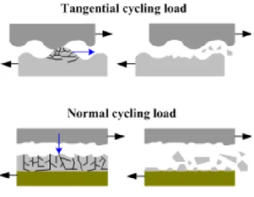
Fatigue wear is related to the repeated loading and unloading cycles to which the materials are exposed. This may induce the formation of subsurface or surface cracks, which eventually, can result in the breakup
19 of the surface with the formation of large fragments, leaving large pits on the surface. Localized fatigue may occur on a microscopic scale due to continuous sliding contact of asperities on the surface of solids in relative movement. The fatigue of materials may be manifested by the occurrence of elastic and plastic deformation, hardening, or softening the material and appearance of cracks and their propagation. Since shear stresses below the surface tends to be larger, there is a higher probability of occurrence of subsurface cracks. However, cracks can still be initiated from the surface by mechanical and chemical interaction between contacting surfaces and surrounding environment or the interfacial element (Figure 2.6). The surface fatigue, in the case of sliding contact, may be associated with mechanisms of adhesion or abrasion, since the repetitive sliding of hard asperities on a solid surface can lead to the formation and propagation of cracks on the surface or subsurface [2,7,8].
Figure 2.6 - Different types of fatigue wear due cyclic applied loads 3
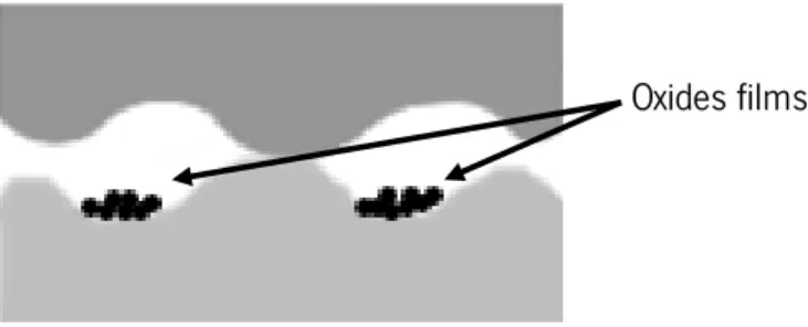
The tribochemical wear, also known as wear by corrosion or oxidation, results from continuous removal of material and formation of new layers at the contact surfaces involving chemical reactions. In presence of atmospheric oxygen, the tribochemical wear is usually named oxidative wear, with the formation of oxide films on the surface of materials. This wear mechanism occurs during chemical instability of the materials. The thin oxide layer which protects the material is removed and allows corrosion of the material,
Chapter 2: State of the art
20
resulting in dissolution and/or diffusion of chemical elements from one material to another (Figure 2.7) [1,2].
Figure 2.7 - Tribochemical wear effects with oxide films
In many systems, materials that are in tribological contact, beyond the mechanical wear are also exposed to a corrosive environment involving chemical and electrochemical processes [10–14]. Therefore, the term tribocorrosion refers to the surface degradation mechanisms when mechanical we ar and chemical/electrochemical processes interact with each other [10–14]. As referred above, the tribological processes involve many different material loss phenomena. Thus, depending on the situation, this process includes the interaction of corrosion, abrasion, adhesion, or surface fatigue wear processes, being many times linked to the synergy resulting from the coupling of mechanical and environmental effects [12,13,15]. Tribocorrosion is present in many places, such as transportation, mining, metallurgy, chemical and oil industries, food industry or medical prostheses. In this last case, the field of knowledge is called biotribocorrosion due to its relation with biologic environments [14,16–19].
The wear of a mechanical component can be measured by its weight loss, due to an irreversible deformation or by the variation of surface roughness. Tribological tests allow to characterize the friction and wear behavior of materials in sliding contact in the absence or presence of a lubricant.
In the technical literature, wear equipments (tribometers) are machines used to measure the friction and wear behavior of materials. Figure 2.8 shows a commercial tribometer (Bruker, USA) for reciprocating sliding friction and wear tests. This machine allows a versatility of tests with a wide range of loads and may allow to perform micro or macro scale tribological tests. It can operate under a variety of test configurations including pin/ball-on-disc and pin/ball-on-plate, both in dry or lubricated sliding environment. Figure 2.9 shows a micro-abrasion machine (Plint TE66, UK). This equipment allows a maximum load of 5 N between a rotating ball (Ø 25 mm) and the plate sample where a three-body abrasive action is promoted by the presence of slurry containing micro-sized hard particles.
21
Figure 2.8 - Tribometer for friction and wear tests (Bruker, USA), courtesy of the Tribology
Laboratory, UMinho
Figure 2.9 - Micro-abrasion machine (Plint TE66, UK), courtesy of the Tribology Laboratory,
UMinho
2.1.5. Lubrication
In order to minimize or control wear and friction at the contact surfaces, a protective film or a fluid between surfaces in sliding or rolling contact is required as it proved to be an efficient method for this purpose. Thus, the reduction of friction between the bodies in contact also promotes a decrease on the wear of surfaces and reduces the heat generated between the surfaces. Those are the main beneficial effects of the use of liquid lubricants [1,7,8]. Depending on the thickness of the lubricant film, various regimes of lubrication may be defined (Figure 2.10).
Figure 2.10 - Different regimes of lubrication, adapted of [1]
In boundary lubrication solid surfaces are so close to each other, with significant asperity interaction (Figure 2.10). Such regime of lubrication is comparable to the non-lubrication conditions at the contact area, once the presence of lubricant film between the surfaces is very small, in the range 0.005-0.1 µm (Figure 2.11). A good lubricant for this mechanism is one that strongly adheres to the solid surface via
Chapter 2: State of the art
22
molecular forces, preventing the adhesion between the two solids, and thus the occurrence of damage to their surfaces. In fact, friction and wear can be controlled by chemical properties (additives) of the lubricant [1,5,7,8].
In the case of hydrodynamic lubrication regime, the two surfaces in relative motion are completely separated by a lubricant film (Figure 2.10), with a considerable thickness between 1 and 100 µm or more, having a specific film thickness ranging from 10 up to 100 (Figure 2.11). The empty space between the surfaces is filled with a lubricant, generating up by a hydrodynamic effect associated with the relative motion between the bodies. The lubricating film ensures the reduction of the coefficient of friction and wear. The hydrodynamic pressure is low compared to the strength properties of the solids and will not cause appreciable plastic deformation. The condition of hydrodynamic lubrication is governed by the bulk physical properties of the lubricant, mainly by the viscosity [1,5,7,8]. In elastohydrodynamic lubrication, the local elastic deformation of the solids provides a coherent hydrodynamic film, which prevents asperity interaction (Figure 2.10). The combination of the sliding speed, the elastic deformation and the increase in lubricant viscosity allow the formation of a film with sufficient thickness to separate the two contact surfaces. An elastic hydrodynamic film has a thickness ranging from 0.01 up to 10 µm and corresponding specific film thickness in a range of 3-10 (Figure 2.11)[1,5,7,8]. The mixed lubrication regime corresponds to the transition between the boundary lubrication and hydrodynamic lubrication. The surfaces are mostly separated by a thin lubricant film although asperity contact still takes place (Figure 2.10). The total applied load is thought to be partly supported by asperity contacts and hydrodynamic action. Mixed lubrication has been defined with a lubricant film thickness ranging from 0.01 up to 1 µm while a specific film thickness in a range of 1-4 (Figure 2.11) [1,5,7,8].
23 2.2. Biotribology in the oral cavity
The oral environment has a very important role in the tribological behavior of human and artificial teeth and restorative materials [20].
Dental erosion is the combination of several factors such as chemical, biological and behavioral factors. These factors are crucial and helps to explain why certain people present more erosion on the teeth than others [21]. For example, acidic drinks increase the acidity in the mouth (pH) and can decrease the hardness and the elastic modulus of enamel, resulting in the loss of dental hard tissue (tooth wear) [22,23].
Saliva has been considered a very important biological factor in the case of dental erosion. Several salivary defensive mechanisms act during the erosive process, such as the dilution and clearance of erosive agent from the mouth, neutralization and buffering of acids. These mechanism are slowing down the rate of enamel dissolution through the ion effect by salivary calcium and phosphate. Erosion can be related with the low salivary flow and low protecting capacity. The enamel pellicle that cover the tooth enamel, protects the oral surfaces against wear originated from masticatory contacts and determines the adherence of microorganisms pellicle that can protect the teeth of an acid environment [24]. So, the protective
Figure 2.11 - Variation of coefficient of friction with the specific film thickness (h/𝜎), adapted of [7]
Chapter 2: State of the art
24
properties of saliva are extremely significant for minimizing the corrosive effects of acids on teeth and restorations. Saliva can supply calcium and phosphate ions for the enamel remineralization [20,21,23]. Even if the contact is tooth-to-tooth or restorative material-to-natural tooth, it has been mention that the wear is a result of four mechanisms such as: abrasion (wear at non-contacting sites together with a number of other situations which cannot be ascribed to erosion or attrition), attrition (describe the physiological wearing away of dental hard tissue as a result of tooth-to-tooth contact with no foreign substance intervening) (Figure 2.12), erosion (describe surface loss attributed to chemical effects. These are usually acidic and may be the result of extrinsic causes such as dietary acids or intrinsic as a result of gastric regurgitation – in tribology this is known as corrosive wear) and abfraction (that includes fatigue) [20,25,26]. Demastication and resorption are other two mechanisms mentioned in technical literature that affect the teeth and lead to an irreversible loss of tooth structure from the external surface. Demastication is the mechanical interaction between food and teeth. Resorption defines the process of biological degradation of substances produced by the body [25].
Figure 2.12 - Erosion caused by refrigerant and attrition caused by bruxism [27]
The tooth wear has significant clinical consequences both aesthetic and functional. The loss of the tooth surface caused by abrasion is the most common clinical problem. Some epidemiological studies estimated that 97% of the teeth loss is caused by wear, with 7% of the population requiring treatment. If the wear is not controlled, the enamel will eventually crack causing exposure of dentin which in turn will accelerate the wear rates, resulting in disastrous effects such as unacceptable damage to occlusion surfaces, alteration of masticatory movements, hypersensitivity of dentin and disorders of the dental pulp [20].
25 2.3. Prostheses and dental implants
2.3.1. Dental implants
The replacement of a missing tooth is a very old process. The ancient cultures used sometimes stone, shells, bones and gold or even other human or animal teeth. However, this practice did not become popular, once that was identified to be the reason for infectious diseases and even deaths [28]. In 1809, Maggiolo developed a gold post anchor into fresh extraction sockets. After the healing process, he attached a tooth to the gold post. This has extraordinary similarity with the modern dental implant procedures. Concerning teeth losses during World War II, there was an interest growing in the design of biocompatible substitutes as well as the possible shape of implants. Dr. Norman Goldberg in association with Dr. Aaron Gershkoff were pioneers in teaching techniques on sub-periosteal implants in dental schools around the world [28,29].
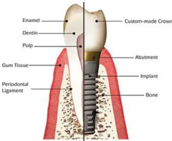
Nowadays, dental implants are increasingly used for the replacement of missing teeth and to support dentures, providing health to patients. Furthermore, this technique have the purpose of providing additional masticatory units [30]. Dental implants correspond to artificial substitutes for natural roots of teeth and have the function of the fixed support of the ceramic crown, which replaces the natural tooth (Figure 2.13).
Chapter 2: State of the art
26
Figure 2.13 - Difference of the constitution of natural and artificial tooth4
Dental implants are fixed to the inside of the gums and in contact with the jawbone. It is essential to ensure that the body does not reject the implant. Due to this problem, the material must be used respecting certain conditions, in particular the appropriate mechanical properties for the function to be performed by the implant and biocompatibility, as well [31].
The osseointegration must occur after the introduction of the implant, i.e. the implant needs to interact with the bone cells (osteoblasts) to form a stable structure [30,32--34]. This process can be improved using certain treatments (e.g. sandblasting, anodic treatment, etc.) or coating on the surface of the material [12,13,30,32,35,36]. The osseointegration concept emerged in 1952, through a fortuitous discovery, made by Per Ingvar Bränemark, when the application of a titanium chamber in vivo research of the tibia of a rabbit, being present a strong integration of the chamber applied with the surrounding bone. Bränemark in 1983 [as cited in 29] defined this concept as a direct structural and functional connection of the bone tissue and the implant surface subjected to functional loads. With the use of titanium in dental implants, there has been a significant evolution in terms of osseointegration [36].
27 2.3.2. Biomedical requirements
In order for dental implants to have success at a long-term and short-term, it is essential to comply with some conditions, such as: biocompatibility, osseointegration, tribocorrosion resistance, resistance to fatigue and corrosion and proper mechanical properties (which provide to the implant stability). These conditions will be affected by parameters such as the surface properties (roughness, topography, formation of oxides, hydrophilicity), geometry and chemistry composition [36-38].
The fixation is a requirement for the implant to have proper support, thus producing a successful implantation. Some properties of the surface, as well as the composition, hydrophilicity and the roughness correspond to characteristics that have an important role in the interaction between the implant and the tissue contributing directly to the quality and rate of osseointegration. The response to the environment, structural integrity and the interaction of cells with the implant are influenced by the characteristics of the surface. The hydrophilicity is also influenced by the constitution of the surface, being that the surfaces which have a greater hydrophilicity are more desirable in terms of the interaction of the implant with the biological fluids, cells and tissues. It's possible to divide the roughness in three categories taking into account the scale of the topological dimensions (macro, micro e nano). This roughness influences the osseointegration and biomechanical fixation to the implant. The composition and the loads to which the implant is subject are critical parameters for protein adsorption and cell attachment [37,38].
2.3.3. Materials used in dental implants
There are many types of materials used in dental implants, for example: metals, ceramics and poly mers. The three most used metals for implants are stainless steel, CoCr alloys and Ti alloys [10,12,39,40].
Regarding ceramics, the most studied are Alumina (Al2O3), Zirconia (ZrO2) and ceramic based-composites.
For example, zirconia have some characteristics that makes it a promising material for dental implants, because of its esthetics benefits and less bacterial adhesion on the material [41–44]. Concerning polymers, they are used as veneer on metals in order to decrease the transfer of ions to surrounding tissues. There are studies of poly(D,L-lactide) (PDLLA) and poli-ether-ether-ketone PEEK related with dental implants [12,13,45].
Titanium corresponds to a material frequently used by the dental industry because it presents a high biocompatibility, excellent mechanical properties and corrosion resistance. The bone also presents these properties and for this reason titanium became an important material to be applied in dental implants [15,39,46–48]. As titanium is a biocompatible material, it allows the natural functions of the tissue to be
Chapter 2: State of the art
28
restored, not causing rejection by the organism. However, due to the high Young's modulus (110-120 GPa) of titanium as compared with the cortical bone (8-18 GPa), loading occlusion can cause stress shielding to the peri-implant area, making them incompatible [10,12,13,47].
Initially, pure titanium was used for biomedical applications, but due to its low abrasion resistance, the creation of titanium based alloys was required. Ti6Al4V alloy was used originally for aeronautical purposes, since it presents high mechanical strength and better corrosion resistance when compared with pure titanium. The main problem of this alloy in biomedical terms is that the modulus of elasticity exceeds the value of the bone [10,15,47,48]. This, porous titanium was created by powder metallurgy, which has a lower modulus of elasticity and allows the bone to grow normally, making it an important material to use in implants [11,49].
Within the different titanium alloys, the most used is Ti6Al4V alloy, due to the fact that it presents good mechanical characteristics and capacity to resist to corrosion in dental implants. The creation of a layer
of titanium oxide (TiO2), stable and dense on the surface of titanium is responsible for its chemical stability
in the organism [11,15,29]. This oxide layer is spontaneously formed when the surface is exposed to oxygen or environments containing oxygen, having normally a thickness in a range of 2-5 nm. This characteristic, along with good mechanical properties makes titanium and their alloys attractive for use in orthopedic and dental applications [50].
Although all the mentioned advantages of titanium, it has poor wear resistance. On the other hand its degradation by wear increases in contact with body fluids, leading to the release of metal ions into surrounding tissues [15,24]. In dental implants, the contact between abutment and implant is exposed to sliding wear in the presence of saliva and abrasive wear due to hard particles from food intake or tooth brushing [11,15]. In the case of orthopedic articular implants, sliding contact occurs between the articular joints which are exposed to body fluids [51–53]. A major concern of the used of titanium and titanium alloys is on the toxicity of the wear particles released to the body and ions released. The titanium-based surfaces have been linked to inflammatory tissue reactions [51–53]. In particular, a study revealed that Al and V have a cytotoxic effect on human cells [54].
The action of cyclic loading in implantology, produced for example by mastication movements, leads to the development of micro-cracks, which over time tends to increase, and may lead to its breakage. On the other hand, the aggressive chemical environment to which implants are exposed (e.g. oral cavity, body fluids etc.) is favorable to the degradation of metallic parts. Hence, the need of understanding the
29 response of implant materials from the wear and corrosion point of view, i.e., tribocorrosion behavior, is an important issue. It is well known that the tribocorrosion is an irreversible process that occurs at the surface of a material causing degradation due to the combination of wear and corrosion actions that occur simultaneously [24,39,48].
Biocompatible polymers and composites have revealed mechanical and biological properties to replace many parts of the human body, mainly in direct skeletal contact [55,56]. For instance, such materials possess low Young’s modulus values, close to that of human bone, although characterized by low mechanical strength which imposes them some limitations [55,57,58]. Poli-ether-ether-ketone (PEEK), is commercialized for the industry since 1980. It belongs to the Poli-aryl-ether-ketone (PAEK) family that is a group of high-performance thermoplastic polymers, presenting an aromatic backbone molecular chain composed of ketone and ether functional groups [57]. PEEK presents two ether and a ketone groups, as shown in Figure 2.14.
Figure 2.14 - Structural formula of PEEK [56]
PEEK and their composites are increasingly used in different industrial fields due to their attractive mechanical properties and relatively low manufacturing cost [58]. Those materials have higher wear and chemical resistance associated with a high biocompatibility when compared to titanium, titanium alloys or stainless steel [59,60]. Poulsson et al. [61] evaluated the osseointegration of PEEK implants with or without surface treatment by oxygen plasma after 4, 12 and 26 weeks. Results from histomorphometry and mechanical push-out tests revealed a limited inflammatory response associates with a good osseointegration. Additionally, the oxygen plasma surface modification improved osseointegration and implant stability.
Conventional biomedical metals are radiopaque and create artifacts in X-ray radiography, computed tomography (CT), or magnetic resonance imaging (MRI). This is an issue in the use of metallic materials in implantology. Considering PEEK is radiolucent, it is possible to monitor the status of the healing bone around PEEK by using those imaging techniques [57,60].
Chapter 2: State of the art
30
For some implant devices, PEEK reinforced with carbon fibers (CFR-PEEK) can be an alternative depending on the loading. The microstructure of CFR-PEEK concerning the concentration and geometry of the carbon fibers is very important to provide the maximum mechanical strength for biomedical applications [55,57]. PEEK presents a Young’s modulus of approximately 3.6 GPa while CFR-PEEK can have a Young’s modulus around of 24 GPa (closer to the values of the cortical bone) [55,57,58,62]. The tensile strength of PEEK is approximately 95 MPa while for CFR-PEEK is 214 MPa [55,57,58]. Also, the mechanical and tribological properties of PEEK make this polymer an attractive material for biomedical applications [12,44,63–68]. Some authors believe that by using PEEK as a veneer it is possible to overcome the problems that arise in titanium implants due to the ions release to surrounding tissues [69,70]. A recent work on a polymeric veneering material to Ti6Al4V alloy revealed a way to avoid the release of metal ions to the human tissues [13]. The test conditions carried out on PDLLA/Ti6Al4V were similar to the ones used in the present work. PDLLA protected the titanium substrate against wear due to the low coefficient of friction during sliding. That could be a good strategy to reduce the degradation of the titanium surface when placed in bone tissue [13].
Furthermore, PEEK and their composites revealed an excellent thermal and chemical stability, being resistant to a variety of organic and inorganic fluids. Concerning the aggressive environment in the oral cavity, PEEK can be used as a protective layer of metal surfaces against corrosion, being a potential strategy for prostheses and implants applied in dentistry [67,71]. In dentistry, PEEK can be used to synthesize transitional abutments [72], healing caps [73] and orthodontic bite sticks.
2.4. References
[1] B. Bhushan, Principles and Applications of Tribology. John Wiley & Sons, 2013, p. 1008.
[2] Karl-Heinz Zum Gahr, Microstructure and Wear of Materials. Elsevier Science Ltd, 1987, p. 570.
[3] D. Dowson, History of Tribology, 2nd editio. 1998, p. 768.
[4] G. Stachowiak and A. W. Batchelor, Engineering Tribology. Butterworth-Heinemann, 2013, p.
884.
[5] T. Mang, K. Bobzin, and T. Bartels, Industrial Tribology: Tribosystems, Friction, Wear and
Surface Engineering, Lubrication. John Wiley & Sons, 2011, p. 648.
[6] I. M. Hutchings, Tribology: Friction and Wear of Engineering Materials. Butterworth-Heinemann,
31
[7] A. S. Miranda, “Noções básicas de Tribologia.” Universidade do Minho, Guimarães.
[8] K. Holmberg and A. Matthews, Coatings Tribology: Properties, Mechanisms, Techniques and
Applications in Surface Engineering. Elsevier, 2009, p. 576.
[9] S. Wen and P. Huang, Principles of Tribology. John Wiley & Sons, 2012, p. 455.
[10] J. Chen, Q. Zhang, Q. Li, S. Fu, and J. Wang, “Corrosion and tribocorrosion behaviors of AISI 316 stainless steel and Ti6Al4V alloys in artificial seawater,” Trans. Nonferrous Met. Soc. China, vol. 24, no. 4, pp. 1022–1031, Apr. 2014.
[11] M. P. Licausi, A. Igual Muñoz, and V. A. Borrás, “Tribocorrosion mechanisms of Ti 6 Al 4 V biomedical alloys in artificial saliva with different pHs,” J. Phys. D. Appl. Phys., vol. 46, no. 40, p. 404003, Oct. 2013.
[12] M. Sampaio, M. Buciumeanu, B. Henriques, F. S. Silva, J. C. M. Souza, and J. R. Gomes, “Tribocorrosion behavior of veneering biomedical PEEK to Ti6Al4V structures,” J. Mech. Behav. Biomed. Mater., Sep. 2015.
[13] J. C. M. Souza, H. a. Tajiri, C. S. Morsch, M. Buciumeanu, M. T. Mathew, F. S. Silva, and B. Henriques, “Tribocorrosion Behavior of Ti6Al4V Coated with a Bio-absorbable Polymer for Biomedical Applications,” J. Bio- Tribo-Corrosion, vol. 1, no. 4, p. 27, Oct. 2015.
[14] S. Mischler, “Triboelectrochemical techniques and interpretation methods in tribocorrosion: A comparative evaluation,” Tribol. Int., vol. 41, no. 7, pp. 573–583, Jul. 2008.
[15] J. C. M. Souza, S. L. Barbosa, E. Ariza, J.-P. Celis, and L. a. Rocha, “Simultaneous degradation by corrosion and wear of titanium in artificial saliva containing fluorides,” Wear, vol. 292–293, pp. 82–88, Jul. 2012.
[16] T. Richardson, B. Cottis, R. Lindsay, S. Lyon, D. Scantlebury, H. Stott, and M. Graham, Shreir’s Corrosion - Basic Concepts, High Temperature Corrosion, First edit. Elsevier Science, 2009, p. 4000.
[17] D. Landolt, “Electrochemical and materials aspects of tribocorrosion systems,” J. Phys. D. Appl. Phys., vol. 39, no. 15, pp. 3121–3127, Aug. 2006.
[18] L. Benea, F. Wenger, P. Ponthiaux, and J. P. Celis, “Tribocorrosion behaviour of Ni–SiC nano-structured composite coatings obtained by electrodeposition,” Wear, vol. 266, no. 3–4, pp. 398–405, Feb. 2009.
[19] P. Ponthiaux, F. Wenger, D. Drees, and J. P. Celis, “Electrochemical techniques for studying
tribocorrosion processes,” Wear, vol. 256, no. 5, pp. 459–468, Mar. 2004.
[20] Z. R. Zhou and J. Zheng, “Tribology of dental materials: a review,” J. Phys. D. Appl. Phys., vol. 41, no. 11, p. 113001, Jun. 2008.
[21] A. Lussi and T. Jaeggi, “Erosion--diagnosis and risk factors.,” Clin. Oral Investig., vol. 12 Suppl 1, pp. S5–13, Mar. 2008.
Chapter 2: State of the art
32
[22] M. Barbour and D. Parker, “Human enamel dissolution in citric acid as a function of pH in the range 2.30≤ pH≤ 6.30–a nanoindentation study,” Eur. J. …, vol. 111, no. 3, pp. 258–262, Jun. 2003.
[23] B. T. Amaechi and S. M. Higham, “Dental erosion: possible approaches to prevention and control.,” J. Dent., vol. 33, no. 3, pp. 243–52, Mar. 2005.
[24] J. C. M. Souza, M. Henriques, W. Teughels, P. Ponthiaux, J.-P. Celis, and L. A. Rocha, “Wear and Corrosion Interactions on Titanium in Oral Environment: Literature Review,” J. Bio- Tribo-Corrosion, vol. 1, no. 2, p. 13, Apr. 2015.
[25] T. Imfeld, “Dental erosion. Definition, classification and links,” Eur. J. Oral Sci., vol. 104, no. 2, pp. 151–155, Apr. 1996.
[26] L. H. Mair, R. W. Vowles, and C. H. Lloyd, “Wear : mechanisms , manifestations and measurement . Report of a workshop *,” vol. 24, no. April 1993, pp. 141–148, 1996. [27] S. Amaral, E. Abad, K. Maia, S. Weyne, M. de Oliveira, and I. Tunãs, “Not carious lesions: the
challenge of the multidisciplinary diagnosis,” Arq. Int. Otorrinolaringol., vol. 16, no. 01, pp. 096–
102, Feb. 2014.
[28] L. Gaviria, J. P. Salcido, T. Guda, and J. L. Ong, “Current trends in dental implants.,” J. Korean Assoc. Oral Maxillofac. Surg., vol. 40, no. 2, pp. 50–60, Apr. 2014.
[29] B. D. Ratner, A. S. Hoffman, F. J. Schoen, and J. E. Lemons, Biomaterials Science: An Introduction to Materials in Medicine. 2004.
[30] C. Bergemann, K. Duske, J. B. Nebe, A. Schöne, U. Bulnheim, H. Seitz, and J. Fischer, “Microstructured zirconia surfaces modulate osteogenic marker genes in human primary osteoblasts.,” J. Mater. Sci. Mater. Med., vol. 26, no. 1, p. 5350, Jan. 2015.
[31] M. Jamshidinia, L. Wang, W. Tong, and R. Kovacevic, “The bio-compatible dental implant designed by using non-stochastic porosity produced by Electron Beam Melting® (EBM),” J. Mater. Process. Technol., vol. 214, no. 8, pp. 1728–1739, Aug. 2014.
[32] F. Mangano, L. Chambrone, R. van Noort, C. Miller, P. Hatton, and C. Mangano, “Direct metal laser sintering titanium dental implants: a review of the current literature.,” Int. J. Biomater., vol. 2014, p. 461534, Jan. 2014.
[33] H.-S. Ryu, C. Namgung, J.-H. Lee, and Y.-J. Lim, “The influence of thread geometry on implant
osseointegration under immediate loading: a literature review.,” J. Adv. Prosthodont., vol. 6, no.
6, pp. 547–54, Dec. 2014.
[34] L. P. Faverani, G. Ramalho-ferreira, E. C. Gaetti-jardim, and R. Okamoto, “Osseointegrated implants : evolution and success,” Salusvita, vol. 30, pp. 47–58, 2011.
![Figure 2.1 - Ancestors moving a statue with water and animal-fat lubrication[3]](https://thumb-eu.123doks.com/thumbv2/123dok_br/17614014.820443/36.892.223.625.122.375/figure-ancestors-moving-statue-water-animal-fat-lubrication.webp)


![Figure 2.12 - Erosion caused by refrigerant and attrition caused by bruxism [27]](https://thumb-eu.123doks.com/thumbv2/123dok_br/17614014.820443/48.892.243.606.560.774/figure-erosion-caused-refrigerant-attrition-caused-bruxism.webp)