P or tugal | 2016 Czech university of Prague
Shivangi Shukla
Seismic strengthening of rammed earth
constructions using reinforced coatings
Shivangi Shukla Seismic s tr engt hening of r ammed ear th cons tr uctions using r einfor ced coatings
Portugal | 2016
Shivangi Shukla
Seismic strengthening of rammed earth
constructions using reinforced coatings
Seismic strengthening of rammed earth constructions using reinforced coatings
DECLARATION
Name: Shivangi Shukla
Email: [email protected]
Title of the Msc Dissertation:
Seismic strengthening of rammed earth constructions using reinforced coatings
Supervisor(s): Daniel V. Oliveira, Rui A. Silva
Year: 2016
I hereby declare that all information in this document has been obtained and presented in accordance with academic rules and ethical conduct. I also declare that, as required by these rules and conduct, I have fully cited and referenced all material and results that are not original to this work.
I hereby declare that the MSc Consortium responsible for the Advanced Masters in Structural Analysis of Monuments and Historical Constructions is allowed to store and make available electronically the present MSc Dissertation.
University: Universidade do Minho
Date: July 18, 2016
Seismic strengthening of rammed earth constructions using reinforced coatings
Erasmus Mundus Programme ii ADVANCED MASTERS IN STRUCTURAL ANALYSIS OF MONUMENTS AND HISTORICAL CONSTRUCTIONS
Seismic strengthening of rammed earth constructions using reinforced coatings
ACKNOWLEDGEMENTS
Good, better, best. Never let it rest. 'Till your good is better and your better is best’ - St. Jerome
Of course, journey to the best is never alone there are always aims, drives and individuals around who make it happen. In my journey to ‘the best’ there has been a contribution of lot of people, some permanent and some who come as guest stars. My words here cannot express my thankfulness to the best but I express my acknowledgement to one and all who were a part of my journey in SAHC and made this dissertation work possible.
I am very grateful to my supervisors Professor Daniel Oliveira and Dr. Rui Silva for creating such an opportunity, guiding and helping me throughout the project. Special thanks to the master student Cristina Barroso and all the laboratory technicians of Structural Laboratory at the University of Minho, who helped with the laboratory experiments and results.
I would like to express my gratitude to all the SAHC professors, staff, colleagues and friends for their immense support and help in Universidade do Minho, Guimarães and Czech Technical University (ČVUT), Prague as well. I also acknowledge the monetary grant provided by the SAHC consortium for this MSc course. The master’s dissertation work was carried out within the framework of projects 007633 and POCI-01-0145-FEDER-016737 (PTDC/ECM-EST/2777/2014) financed by FEDER funds through the Competitivity
Factors Operational Programme - COMPETE and by national funds through FCT –
Foundation for Science and Technology. The funding provided is kindly acknowledged. Also
mentioning EMBARRO Universal for providing materials used in the research work.
The reasons which pushed me forward to take this journey up are the emotional support, strength and confidence from my family which I would personify as my parents, my sister and my fiancé. My work and words are incomplete without mentioning my mentors from India, Professor Nalini Thakur, School of Planning and Architecture, New Delhi; Dr. Arun Menon, Assistant Professor, IIT Madras and Krishnachandran Sethumadhavan, structural engineer, who are the reason for me being a SAHC graduate. And here I am looking forward to see the next ‘best thing’ in my life.
Seismic strengthening of rammed earth constructions using reinforced coatings
Erasmus Mundus Programme iv ADVANCED MASTERS IN STRUCTURAL ANALYSIS OF MONUMENTS AND HISTORICAL CONSTRUCTIONS
Seismic strengthening of rammed earth constructions using reinforced coatings
ABSTRACT
Earth constructions cover 30% of the total built heritage in the world, some of which are Unesco World Heritage listed. Building in rammed earth consists in compacting layers of moist earth within a formwork to erect walls. Rammed earth constructions are known for presenting high seismic vulnerability, due to their high dead-weight, low mechanical properties (especially very low tensile strength) and poor connections between structural elements. During a seismic event of moderate intensity, the walls tend to fail in their plane and in out-of-plane mechanisms.
In South Portugal, the regions of Alentejo and Algarve are seismically active and a significant part of the built heritage is made of rammed earth. The structural vulnerability of rammed earth buildings puts the heritage and the life of their inhabitants at risk. Hence, the mitigation of the aforementioned risks demands the development of adequate interventions for the seismic strengthening of rammed earth constructions. In Peru, coatings reinforced with geomesh have been used for the strengthening of adobe constructions, where this solution has been shown to be highly effective in increasing their bearing capacity and energy dissipation capacity under seismic loading.
This type of solution can also be applied to rammed earth with the same purpose, nevertheless little investigation has been carried out on its development and validation. Little literature available for conservation principles and structural retrofitting makes it even more challenging. The development of this solution, in this case, needs the investigation of compatible materials and of the characterization of its mechanical behaviour. Proceeding in this way will make possible to create bases for proper design, namely with respect to the development of numerical tools. In this context, the main objective of this dissertation is to contribute for the development of the knowledge on the strengthening of rammed earth walls by means of reinforced coatings.
The proposed objective integrates the following methodology: a) literature review on rammed earth construction, namely focused on their seismic behaviour and intervention approaches, and on the strengthening of masonry with reinforced coatings; b) proposal of an approach for strengthening rammed earth constructions with reinforced coatings within the international principles and guidelines for heritage conservation; c) execution of an experimental program dedicated to the characterization of the behaviour of the solution (individual materials and interaction). The experiments were carried out in the structural laboratory of University of Minho, followed by evaluating the results and discussing the findings.
Seismic strengthening of rammed earth constructions using reinforced coatings
Erasmus Mundus Programme vi ADVANCED MASTERS IN STRUCTURAL ANALYSIS OF MONUMENTS AND HISTORICAL CONSTRUCTIONS
Seismic strengthening of rammed earth constructions using reinforced coatings
RESUMO
A construção em terra cobre 30% de todo o património construído no Mundo, onde se inclui alguns sítios listados como património Mundial pela Unesco. Construir em taipa consiste em compactar camadas de terra húmida no interior de um molde para erguer paredes. As construções em taipa são conhecidas por apresentarem elevada vulnerabilidade sísmica, devido ao seu elevado peso próprio, propriedades mecânicas baixas (especialmente uma resistência à tração muito baixa) e fracas ligações entre elementos estruturais. Durante um evento sísmico de intensidade moderada, as paredes de tendem a romper no seu plano e através de mecanismos de rotura para fora do plano.
No Sul de Portugal, o Alentejo e o Algarve são regiões sismicamente ativas, onde uma parte importante do património construído é de taipa. A vulnerabilidade sísmica das construções em taipa põe em risco a sua preservação e a vida dos seus moradores. Assim, a mitigação destes riscos exige o desenvolvimento soluções de reforço sísmico adequadas para construções de taipa. No Perú, têm sido utilizados rebocos armados com geomalhas no reforço de construções de adobe, onde esta solução tem demonstrado enorme eficiência no melhoramento da capacidade resistente e da capacidade de dissipar energia da ação sísmica.
Este tipo de solução pode ser aplicado com o mesmo objetivo, porém tem sido desenvolvida pouca investigação sobre o desenvolvimento e validação da técnica. A pouca bibliografia existente sobre princípios de conservação e reforço estrutural, tornam esta tarefa ainda mais difícil. Neste caso, o desenvolvimento desta solução requer a investigação de materiais compatíveis e da caracterização do comportamento mecânico. Através desta abordagem, tornar-se-á possível criar bases para dimensionamento, nomeadamente no que diz respeito ao desenvolvimento de ferramentas numéricas. Neste contexto, o principal objetivo desta dissertação é contribuir para o desenvolvimento do conhecimento sobre o reforço de paredes de taipa com rebocos armados.
O objetivo proposto será conseguido seguindo a metodologia seguinte: a) revisão bibliográfica sobre construções em taipa, nomeadamente focada no seu comportamento sísmico e abordagens de intervenção, bem como no reforço de alvenaria com rebocos armados; b) proposta de uma abordagem o reforço sísmico de construções de taipa com rebocos armados, seguindo princípios e recomendações internacionais para a conservação do património; c) execução de um programa experimental dedicado à caracterização do comportamento da solução (dos materiais individuais e da sua interação). T Os ensaios foram realizados no laboratório de estruturas da Universidade do Minho, seguindo-se a análise e discussão dos resultados.
Seismic strengthening of rammed earth constructions using reinforced coatings
Erasmus Mundus Programme
Seismic strengthening of rammed earth constructions using reinforced coatings TABLE OF CONTENTS LIST OF FIGURES ... xi LIST OF TABLES ... xv 1. INTRODUCTION ... 1 1.1 Context ... 1 1.2 Motivation ... 3 1.3 Objectives... 5
1.4 Methodology and outline ... 6
2. Strengthening of RE constructions ... 9
2.1 Introduction ... 9
2.2 Earth construction in seismic zones ... 10
2.2.1 Seismic behaviour of adobe ... 11
2.2.2 Seismic behaviour of RE ... 13
2.2.3 RE in seismic areas ... 14
2.3 Principles for earthquake resistant houses ... 16
2.4 Reinforced coatings ... 20
2.5 Case studies on seismic strengthening solutions ... 24
2.5.1 Internal reinforcement with bamboo grid ... 25
2.5.2 External reinforcement with wire mesh ... 26
2.5.3 External reinforcement with polymer mesh ... 26
3. Considerations on the use of FRCM in RE ... 31
3.1 Introduction ... 31
3.2 International scientific committees ... 32
3.3 General principles for conservation ... 34
3.3.1 General criteria ... 34
3.3.2 Researches and diagnosis ... 34
3.3.3 Remedial measures ... 35
3.4 Compatibility concerns of FRCM ... 35
Seismic strengthening of rammed earth constructions using reinforced coatings
Erasmus Mundus Programme x ADVANCED MASTERS IN STRUCTURAL ANALYSIS OF MONUMENTS AND HISTORICAL CONSTRUCTIONS
4. Characterisation of the raw materials ... 39
4.1 Introduction ... 39
4.2 Characterisation of rammed earth ... 40
4.2.1 Granulometry ... 40
4.2.2 Plasticity ... 41
4.2.3 Proctor compaction test ... 42
4.3 Characterisation of mortars ... 43
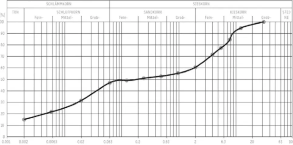
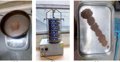
4.3.1 Granulometry ... 43
4.3.2 Bulk density ... 48
4.3.3 Flow consistency and workability ... 50
4.3.4 Linear shrinkage ... 53 4.4 Characterisation of meshes ... 54 5. Mechanical characterization ... 59 5.1 Introduction ... 59 5.2 Characterization of RE ... 59 5.3 Characterization of mortars ... 60
5.4 Direct pull-off test ... 69
5.5 Tensile tests of meshes ... 75
5.6 Comparison of modulus of elasticity of materials ... 78
6. ConclusionS and future works ... 81
6.1 Main conclusions ... 81
6.2 Future research ... 83
Seismic strengthening of rammed earth constructions using reinforced coatings
LIST OF FIGURES
Figure 1: Map of the worldwide distribution of earth construction (Gramlich, March 2013) .... 2 Figure 2: The twelve main techniques for earth constructions (Auroville, 2016). ... 4 Figure 3: World map of (a) earth construction distribution and (b) of the regions with
important seismic hazard (De Sensi, 2003) ... 5 Figure 4: Distribution of earth construction in Portugal;(a) Rammed earth; (b) Adobe and (c) Wattle and daub (Rocha, 2005) ... 6 Figure 5: Ancient earthen structures (a) citadels of Chan-Chan and (b) Arg-e Bam (Blondet & Aguilar, 2007) ... 10 Figure 6: Adobe houses with seismic damage (a) Vertical cracks at corner of front wall and (b) Diagonal shear cracks (Blondet & Aguilar, 2007) ... 11 Figure 7: Typical damage pattern in earth constructions due to seismic action (Webster and Tolles, 2000) extracted (Tavares, 2012) ... 12 Figure 8: Typical earthquake-damage pattern in rammed earth buildings: (a) vertical
cracking, starts at the base and sometimes runs throughout the height; (b) Vertical cracking at corners; (c) In-plane shear cracking (Ziegert, 2010) ... 14 Figure 9: Typical damages of RE constructions from Bhutan, after the Sikkim-Bhutan
earthquake: (a) corner cracks; (b) separation of old and new walls; (c) diagonal cracks at the openings ... 14 Figure 10: Typical damages of RE constructions (a) Separation of corner walls; (b) vertical wall cracks and (c) corner failure ... 15 Figure 11: Wattle-and-daub structure that survived after a heavy earthquake in Guatemala (Minke, 2001) ... 16 Figure 12: Dangerous and optimal placement of house on a slope; modified (Minke &
Schmidt, 2015) ... 17 Figure 13: Seismic performance of different plan shapes used for earth construction ... 17 Figure 14: RE model with square plan developed a large crack after the 2nd stroke, (a) one
part separated after 3rd strokes and (b) collapse after 4th stroke (Minke, 2001) ... 18
Figure 15: Circular RE models (a) first crack appeared only after 3rd stroke and (b) after 6th
stroke a small part was separated (Minke, 2001) ... 18 Figure 16: Recommended proportions for earth walls (a) for the free ends and (b) corner extension for the connection (Minke, 2001) ... 19 Figure 17: Internal reinforcement with vertical rods (a) foundation of external walls should be at least 40cm deep and made with stones; (b) separation of roof and wall system with ring beam on top and bottom (c) floating foundation with plastic bags filled with pebbles (Minke, 2001) ... 19 Figure 18:Possibilities of fixing wooden ring beams (a) wooden beams in RE wall; (b) vertical post fixed to a double ring beam in RE wall and (c) adobe walls reinforced by buttresses and ring beams on the top of the walls (Minke & Schmidt, 2015) ... 20 Figure 19: Laboratory models (a) general scheme of the strengthening system (b) fixing with
Seismic strengthening of rammed earth constructions using reinforced coatings
Erasmus Mundus Programme
xii ADVANCED MASTERS IN STRUCTURAL ANALYSIS OF MONUMENTS AND HISTORICAL CONSTRUCTIONS
Figure 20: Basalt nets and high strength steel fabrics (Garbin, et al., 2014) ... 22 Figure 21: Pull off test failures obtained for: (a) masonry reinforcement with basalt net 1; (b) basalt net 2 and (c) with steel fabrics (Garbin, et al., 2014) ... 23 Figure 22: Failure modes in SRG specimens (a) debonding at the substrate-matrix interface in specimens with anchorage; (b) at the textile-matrix interface in specimens; (c) failure modes in BTRM specimens: debonding at the substrate-matrix interface in specimens (d) and slipping of the fibre rovings from the matrix in specimens (Felice, et al., 2014) ... 24 Figure 23:(a) 40cm high T shaped elements with 80cm length 30cm width and 14cm thick with bamboo reinforcement; (b) opening for windows (Minke, 2001) ... 25 Figure 24: Preparation of experimental models in laboratory (a) internal cane mesh
reinforcement with horizontal placement; (b) external wire mesh reinforcement and (c) failure of the experimental model (Blondet & Aguilar, 2007)... 25 Figure 25: Reinforced model after seismic test reinforced house after the 2001 earthquake Adobe buildings with external wire mesh reinforcement (Blondet & Aguilar, 2007) ... 26 Figure 26: Drawings of the adobe models with 0.26m thick walls 3.21m long four walls (Blondet, et al., 2006) ... 27 Figure 27: Construction of the real scale house models in the laboratory (a) unreinforced model and (b) external geogrid mesh reinforcement with 75% (Blondet, et al., 2006) ... 27 Figure 28: Real scale adobe model (a) with plastic mesh reinforcement and (b) laboratory experiment (Blondet, et al., 2006) ... 28 Figure 29: State of UNESCO World Heritage sites (a) earth construction areas all around the world with UNESCO listed sites (AEI, 2016) and (b) statistics of endangered earthen sites over last 30 years (UNESCO, n.d.) ... 31 Figure 30: Map of Earthen heritage at Europe in 2011 (Incognita, 2016)... 33 Figure 31: Optimal PSD curve for RE recommended by the German Code (Röhlen & Ziegert, 2014) ... 40 Figure 32: PSD curve of the soil S6 (corrected with soil S5 and S4 types) (Silva & André, 2013) ... 41 Figure 33: Consistency of soil compared with recommended ranges of values (Silva &
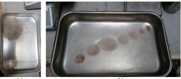
André, 2013) ... 42 Figure 34: Compaction curve of soils S6 (Silva & André, 2013) ... 43 Figure 35: Cement, hydraulic lime and sand used to manufacture mortar M1. ... 44 Figure 36: Dry sieving of sand (a) total mass of the sand taken for sieving; (b) vibration for 10 minutes and (c) particles size distribution of the sand in M1 ... 44 Figure 37: PSD curve of the sand for M1 ... 45 Figure 38: Dry sieving of earth mortar M2 (a) total mass taken and (b) fractions divided with different size sieves. ... 46 Figure 39: Granulometry with sedimentation procedure; (a) heating; (b) sieving; (c)
measurement of the suspension density and (d) measurement of temperature after 48 hours. ... 47 Figure 40: PSD curve of the earth mortar M2. ... 48 Figure 41: Mass of the material weighed in 1000ml container for (a) sand and (b) cement . 48 Figure 42: Flow table test for cement mortar M1 (a) fresh mortar placed in the mould; (b) and (c) difference in diameters of spread mortar with different water content ... 51
Seismic strengthening of rammed earth constructions using reinforced coatings
Figure 43: Flow table tests of mortar M2 (a) mixture with given moisture content of 20%, showing water excess; (b) mould before and (c) after jolting spread ... 51 Figure 44: Variation of the workability with the W/S for cement mortar M1 ... 52 Figure 45: Variation of the workability with the W/S for earth mortar M2. ... 53 Figure 46: Moulds of mortar specimens: (a) for cement mortar M1 showing no shrinkage and (b) for earth mortar M2 showing 0.33% linear shrinkage. ... 54 Figure 47: Set up of the meshes in the testing machine (a) glass fibre mesh and (b) metallic mesh ... 55 Figure 48: Set up of the meshes in the testing machine (a) high density plastic mesh and (b) low density plastic mesh ... 55 Figure 49: Stress-strain curves of the RE cylindrical specimens manufactured with soil S6 (Dominguez, 2015) ... 59 Figure 50: Cement mortar M1 in (a) fresh state and (b) hardened state after demoulding ... 60 Figure 51: Earth mortar/M2 in (a) fresh state and (b) hardened state before demoulding .... 61 Figure 52: Destructive testing for flexural strength in mortar specimens (a) placement of the prism on the testing machine; failure of (b) cement mortar M1 and (c) earth mortar M2 ... 62 Figure 53: Destructive test for compressive strength on mortar specimens (a) failure of cement mortar M1 and (b) development of cracks in earth mortar M2. ... 63 Figure 54: Preparation of cylindrical specimens for uniaxial compression test (a) cement mortar M1 specimen kept packed with plastic film and (b) application of gypsum on the specimens for testing. ... 65 Figure 55: Stress-strain curves for four cement mortar M1 specimens i.e. M1C1-M1C4 plotted using external LVDT reading ... 66 Figure 56: Stress-strain curves for four cement mortar M1 specimens i.e. M1C1-M1C4 plotted using internal LVDTs reading ... 66 Figure 57: Stress-strain curves for three earth mortar M2 specimens i.e. M1C1-M1C3 plotted using external LVDTs reading ... 67 Figure 58: Stress-strain curves for three earth mortar M2 specimens i.e. M1C1-M1C3 plotted using internal LVDTs reading ... 68 Figure 59: Uniaxial compression test for cement mortar M1 (a) Setting of the specimen in the testing machine; (b) formation of a diagonal cracks and palling of the specimen surface from top and bottom; (c) separation with main vertical/diagonal crack and (d) symmetric
separation of specimen with 3 vertical cracks ... 69 Figure 60: Uniaxial compression test for earth mortar M2 (a) Setting of the specimen in the testing machine; (b); (c) vertical diagonal cracks and (d) separation of the specimen with diagonal crack. ... 69 Figure 61: Preparation of pull-off test (a) rendering of mortars; (b) drilling of holes with clamp support; (c) gluing of pull heads on test specimens with adhesive and (d) fixing of apparatus on pull heads ... 70 Figure 62: Schematic of the test apparatus setup with substrate (ASTM:C1583, 2004) ... 71 Figure 63: Failure modes in pull off test (a) Mode 1 failure in substrate; (b) Mode 2 failure in bond; (c) Mode 3 failure in overlay and (c) Mode 4 failure at glue and overlay interface. Modified (CAE, 2016) ... 72
Seismic strengthening of rammed earth constructions using reinforced coatings
Erasmus Mundus Programme
xiv ADVANCED MASTERS IN STRUCTURAL ANALYSIS OF MONUMENTS AND HISTORICAL CONSTRUCTIONS
Figure 64: Tested specimens from pull-off test (a); (b) Mode 1/cohesive and Mode
2/adhesive failures visible in earth mortar M2; (c) and (d) Mode 1/cohesive failures in cement mortar M1 ... 75 Figure 65: Schematic of tensile strength test mesh specimen ... 76 Figure 66: Tensile stress-axial strain curves for some of the tested meshes in the y direction ... 76 Figure 67: Tensile failures in (a) high density plastic mesh and (b) low density plastic mesh ... 77 Figure 68: Tensile failures in (a) glass fibre mesh and (b) metallic mesh... 77
Seismic strengthening of rammed earth constructions using reinforced coatings
LIST OF TABLES
Table 1: Advantages and Limitations of rammed Earth ... 3
Table 2: PSD of soil S6 compared with the German recommendations for rammed earth (Silva & André, 2013) ... 41
Table 3: Atterberg limits of soil S6 (Silva, 2013) and recommended values ... 42
Table 4: Compaction properties of soil S6 (Silva, 2013) and recommended values. ... 43
Table 5: PSD of mortar M1 obtained from dry sieving. ... 45
Table 6: PSD measurement for Earth mortar M2 particles with dry sieving ... 46
Table 7: PSD measurement for earth mortar M2, obtained from the sedimentation test. ... 47
Table 8: Calculation of bulk density of sand for cement mortar M1 using EN 1097-3. ... 49
Table 9: Calculation of bulk density of lime for cement mortar M1 using EN 1097-3. ... 49
Table 10: Calculation of bulk density of cement for cement mortar M1 using EN 1097-3. ... 49
Table 11: Calculation for the proportion of materials in cement mortar M1 ... 50
Table 12: Calculation of bulk density of earth mortar/M2 using EN 1097-3 ... 50
Table 13: Calculation of flow consistency/workability for cement mortar M1 ... 52
Table 14: Calculation of flow consistency/workability for earth mortar M2 ... 52
Table 15: Comparison of meshes on the basis of prices and density of threads... 56
Table 16: Results of the RE cylindrical specimens for soil S6 tested under compression (Dominguez, 2015) ... 60
Table 17: Calculation for flexural strength for cement mortar M1 ... 62
Table 18: Calculation for flexural strength for earth mortar M2 ... 62
Table 19: Calculation for compressive strength for cement mortar M1 ... 63
Table 20: Calculation for compressive strength for earth mortar M2 ... 64
Table 21: Results of cylindrical specimens tested under compression for cement mortar M1 ... 65
Table 22: Results of cylindrical specimens tested under compression for earth mortar M2 . 67 Table 23: Calculation of tensile bond force for cement mortar M1 ... 71
Table 24: Calculation of tensile bond force for earth mortar/M2 ... 72
Table 25: Characterization of failures for cement mortar M1. ... 73
Table 26: Characterization of failures for earth mortar M2. ... 74
Table 27: Comparison in between the selected meshes ... 78
Seismic strengthening of rammed earth constructions using reinforced coatings
Erasmus Mundus Programme
Seismic strengthening of rammed earth constructions using reinforced coatings
1. INTRODUCTION 1.1 Context
‘Build your architecture from what is beneath your feet’ - Hasan Fathy
The aforementioned statement, from the great Egyptian architect Hasan Fathy, holds a deep meaning describing his thoughts for earth construction. Though these words came in 20th
century, mankind understood the power of earth construction since the inception of human settlements. For millions of years, mankind lived with perfect harmony with nature using locally available natural materials like earth, timber/bamboo, stone, etc. From primitive construction to permanent dwellings in ancient civilizations, raw earth was extensively used for building, while keeping the sustainable balance in the environment. Earth construction techniques have been known for over 9000 years, where earth was used as a building material not only for dwellings but also for religious buildings. The building methods involved were economic, robust and required only simple technology (AEI, 2016).
Nowadays, many countries still present examples of earth constructions, but historically these are associated to dry climatic/arid zones where wood was scarce. Mud bricks and rammed earth were used throughout the ancient Middle East, where Jericho is the earliest city reported to be built with raw earth. The oldest known buildings in RE (rammed earth) are 10,000 years old and were built at Catahyouk, near Konya in Turkey. Now, it constitutes a famous archaeological site with ongoing excavations, where evidences of mud bricks, cob and RE have been found. All dwellings found were load bearing with earthen walls and roofs. Chinese rammed earth buildings are 4500 years old, some parts of the Great Wall of China (UNESCO listed world heritage site) were built in RE over 2000 years ago. Teotihuacan sun pyramid (Mexico) has 70 m tall, 1900-year-old (built between the 300 and 900 AD) and its core consists of around 2 million tons of RE cladded faced with stone. In Spain, RE was also used to build the Alhambra palace and fortress, which is now listed as UNESCO World Heritage site (Ciancio, et al., 2015).
Earth has been used as a building material in many places in the World, namely in Nile’s shore in Egypt, the fertile valleys of China, Tibet, Iran, India, Nepal, Yemen or the Andes Mountains in Peru and Europe. The RE technique was brought to Europe by the Romans and Phoenicians and it was used for more than 2,000 years. The grain stores of Ramasseum, in adobe, from 1300BC in the old city of Thebes still exist in Egypt (Anon., 2016). In Northern Europe the oldest mud brick walls are found in Heuneburg, Germany, and date back to the 6th
century BC. Bronze Age evidences also showed that earth was used as an infill in timber-framed dwellings in this region. The archival writings of Pliny were referring to the construction of RE forts in Spain by the end of the year 100 BC. In almost all pre-Columbian cultures adobe construction is very common, namely in Mexico, Central America and South America (Minke, 2006). With respect to modern RE constructions, several important architectural examples exist, such as the Rauch house in Austria, with three storey load bearing unstabilised rammed walls, and the Royal Automobile Club in Victoria, which is the biggest modern load bearing
Seismic strengthening of rammed earth constructions using reinforced coatings
Erasmus Mundus Programme 2 ADVANCED MASTERS IN STRUCTURAL ANALYSIS OF MONUMENTS AND HISTORICAL CONSTRUCTIONS
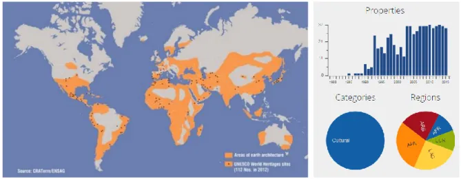
Figure 1: Map of the worldwide distribution of earth construction (Gramlich, March 2013)
The worldwide distribution of earth construction is pictured in the map of Figure 1, where it is clear that adobe (mud brick) and RE are the most widely used techniques. In addition, these are techniques used since ancient times, as is evidenced by the adobe dwellings dating from 8000 to 6000 BC, discovered in Russian Turkestan, or the foundations in RE from 5000 BC, discovered in Assyria. The use of adobe and RE continued over the times, where Bam citadel, Iran, presents constructions with 2500 years old, while the fortified city of Draa valley in Morocco, is around 250 years old. (AEI, 2016). The RE technique slowly emerged in many areas of the World, spread by the Spanish conquerors as they settled their colonies. In the Medieval period (13th -17th centuries), earth was frequently used throughout Central Europe
as infill in timber-framed structures.
From 15th to 19th centuries RE technique got widespread in France as Pisé. In Germany, the
oldest inhabited house made in RE walls dates back to 1795 (Minke, 2006). RE construction attained its popularity in the US from 1780 until about 1850 (Anon., n.d.), while in Canada, it emerged in between 1838 and 1841. The period from the 1920s through the 1940s was active for studies on RE construction in the US. Many institutions carried out extensive research on the subject. Houses were built inexpensively under some schemes in association with architects and provided accommodation to low-income families. After the World War II the costs of modern building materials fell and RE became less preferable. In fact, RE construction lost its popularity with the advancement and development of modern building materials in the 21st century, to which also contributed some of disadvantages of these constructions, namely
their poor seismic behaviour. The advantages and disadvantages of RE constructions are listed in Table 1.
adobe and sun dried brick clay lump and rammed earth reinforced mud, wattle and daub
Seismic strengthening of rammed earth constructions using reinforced coatings
Table 1: Advantages and Limitations of rammed Earth
Advantages Limitations
- simple, fast and inexpensive construction
- load bearing capacity - sustainable/
recyclable/biodegradable - non-toxic and termite-resistant - non-combustible/resistant to fire - excellent thermal and acoustic
characteristics - durable/ long lifespan
- labour intensive, which can result in higher building cost in developed countries - requires using adequate formworks
- maintenance demanding construction, especially in the case of unstabilised RE
- poor seismic performance of unstabilized RE - susceptible to damage by water/ moisture - additional insulation and vapour barriers required - carbon benefits are reduced with cement
stabilisation
Over the time, the RE technique kept developing with the experience and depended on climate/geological conditions of the region, structural stability and diverse building requirements (Schroeder, 2015). In recent years, with the advancement of research and development in structural analysis and material stabilisation, RE construction technique has been able to reclaim its status as a preferable building material. However, the seismic performance of these constructions is still a challenge in the fraternity of structural engineering, conservation as well as architectural designing. It has become a prevalent research topic worldwide and this dissertation is a footstep to contribute to the concerned subject.
1.2 Motivation
The diversity of earthen structures ranges from simple forms of dwellings to massive
monumental sites of great intricacy. About 10% of the World heritage list of UNESCO are
earthen construction sites (Getty, 2016). According to United Nations, one third of the human
population lives in earthen dwellings, in developing countries it is about 50 % and at least 20% of urban and suburban populations residing in earthen houses (AEI, 2016). The last decade has witnessed significant natural calamities, which caused heavy losses in terms of human fatalities, property and heritage loss. Along with natural disasters, the increasing urbanization and modern building technologies are also a great threat to earth constructions. The traditional construction methods and practices are disappearing, and moreover it is also becoming harder to find a skilled labour in the field. Figure 2 shows the twelve major earth construction techniques.
Seismic strengthening of rammed earth constructions using reinforced coatings
Erasmus Mundus Programme 4 ADVANCED MASTERS IN STRUCTURAL ANALYSIS OF MONUMENTS AND HISTORICAL CONSTRUCTIONS
Figure 2: The twelve main techniques for earth constructions (Auroville, 2016).
Risk assessment and disaster management involved with natural disasters (floods/earthquakes) or human impacts is a major concern today. Due to the mismanagement of resources, risk of ecological disasters is also present, moreover it affects the built environment directly or indirectly. Disaster resistant constructions are of utmost need in all over the world, but they also must account for the affordability so that the solution can be accessible to everyone.
Some studies on the mechanical behaviour and seismic performance of RE have been performed in the recent years. Research groups from Peru and Mexico have been contributing with experimental research on adobe construction. The USA and Australia have been focused, since 1980, on the study of stabilized RE. Moreover, in these countries there are documents regulating earth construction. In 1980-90, India stepped forward with CSEB technology. The seismic performance of RE is almost absent from scientific research, which represents a serious gap in knowledge regarding the performance characterization of earth construction. The current work is in line with the context and ongoing research in Portugal, where the Department of Civil Engineering from University of Minho is taking an important participation.
Seismic strengthening of rammed earth constructions using reinforced coatings
1.3 Objectives
Earth constructions are found spread all around the World, where many of them were erected on zones with high seismic hazard (Figure 3). Earth constructions, such as RE, are very vulnerable to earthquakes due to their low strength (compressive and tensile), brittle behaviour, high dead-weight and poor connections between structural elements. Even in a moderate intensity seismic action, the walls tend to fail (in-plane/out-of-plane mechanisms). The seismic performance and strengthening of these structures is a challenging topic, where knowledge is still scarce.
(a) (b)
Figure 3: World map of (a) earth construction distribution and (b) of the regions with important seismic hazard (De Sensi, 2003)
Portugal is a country threatened by the occurrence of earthquakes with high intensity, where southern region has the highest seismic vulnerability, namely in the regions of Alentejo and Algarve. In these regions, RE constructions are found frequently as shown in Figure 4. These are typically classified, according to their use, in military and civil constructions. The first ones are mainly constituted by, still existing, millenary fortifications built during the Arab occupation, such as the Paderne Castle. The second ones are mainly constituted by dwellings built before 1950s, where a significant part of the population still lives in. In this last case, exterior walls are made of RE, while the interior ones can be made of the same material, adobe masonry or wattle-and-daub. Furthermore, many of these constructions have survived some high intensity earthquakes. However, the high risk of the loss of lives and loss of this important built heritage recalls the urgency in studying the seismic performance of RE constructions, as well as strengthening solutions.
Seismic strengthening of rammed earth constructions using reinforced coatings
Erasmus Mundus Programme 6 ADVANCED MASTERS IN STRUCTURAL ANALYSIS OF MONUMENTS AND HISTORICAL CONSTRUCTIONS
(a) (b) (c)
Figure 4: Distribution of earth construction in Portugal;(a) Rammed earth; (b) Adobe and (c) Wattle and daub (Rocha, 2005)
The risks associated with earthquakes can be overcome with planning and strategies for seismic retrofitting of RE constructions. Research on seismic retrofitting of adobe have been done in Peru, namely with reinforced coatings using ‘geomeshes’. The system increases the bearing capacity and energy dissipation capacity of the structure under seismic loading. The aim of the current research is to apply a similar reinforced coating to RE and assess its effectiveness. Though, very little information is available in the literature. Therefore, this thesis deals with the investigation of compatible materials, specifically with respect to their mechanical behaviour. This work can be a step up in the further development of numerical tools. Hence, the main objective of this dissertation is to contribute for the development of the knowledge on the strengthening of RE walls by means of reinforced coatings. The proposed objective will be fulfilled by means of an experimental program.
1.4 Methodology and outline
The dissertation work aims at assessing the performance of RE wall with reinforced coatings by comparing the results from experimental tests using two different mortars. The methodology adopted for the development of the research work is briefly discussed below. First, a literature review was performed on earth construction, in order to allow understanding the context of the topic. This review was focused on the history of earthen construction, significance and prominence of RE technique across the globe along with the seismic risk associated to earthen heritage; which is being discussed in Chapter 1.
Later, in Chapter 2, the seismic behaviour of RE is described with respect to vernacular strengthening and intervention approaches with some basic principles of earthquake resistant houses. Further discussed are the recent international research done on seismic strengthening of masonry and adobe with reinforced coatings and their results. Lastly, case
Seismic strengthening of rammed earth constructions using reinforced coatings
studies from Peru are discussed with respect to the use of reinforced coatings for seismic strengthening of adobe vernacular dwellings.
In Chapter 3, the global issue of RE conservation is discussed with respect to the problems related with endangered historic sites listed by UNESCO. The significance of international standards and principles for heritage conservation, formed by international organisations are also discussed. Furthermore, it addresses the compatibility of the proposed strengthening method in heritage context and future challenges for its acceptance for historic RE retrofitting. The execution of the experimental work is presented in the last two chapters explaining the laboratory experiments. Chapter 4 deals with the experimental program carried out and presents the selection, preparation and characterization of rammed earth, mortars and reinforcing meshes.
Mechanical properties and results obtained from laboratory tests are presented in Chapter 5. The material strength with corresponding modulus of elasticity is presented for rammed earth, mortars, and meshes. Mortar and rammed earth substrate interface is also assessed. Evaluation of the laboratory tests with conclusions is presented in the final Chapter 6. Future works and recommendations are also discussed later in the chapter. The thesis work presented here is not exhaustive and is being taken forward for further studies and analysis for the same project.
Seismic strengthening of rammed earth constructions using reinforced coatings
Erasmus Mundus Programme 8 ADVANCED MASTERS IN STRUCTURAL ANALYSIS OF MONUMENTS AND HISTORICAL CONSTRUCTIONS
Seismic strengthening of rammed earth constructions using reinforced coatings
2. STRENGTHENING OF RE CONSTRUCTIONS 2.1 Introduction
Over the ages RE constructions, from simple dwelling to complex structures with historical value, have been showing poor seismic behaviour around the world. Adequate knowledge on the subject is still absent, which threatens the life of inhabitants and the preservation of this heritage. This ignorance and inexperience has also led to inadequate seismic retrofit procedures. Hence, the economical, technical, and functional stability requirements is the prime need for the preservation of the heritage in RE. RE is a malleable material and can be used for curves and arches but because of its vulnerability to weather conditions and seismic actions it is not considered as good building material. Earth as a material, cannot resist the effects of moisture. Increasing the water content in RE reduces its strength and stiffness (Jaquin, et al., 2013). The unstabilised earth walls get their strength from the bonding effect of dried clay. The strength is lost if it becomes wet and consequently causes erosion or failure (Anon., 2016). The strength of RE is also reduced with erosion due to wind and driving rain. Seismic activities cause structural damage and sometimes complete failure to unstabilised RE. Strengthening can be done by improving its seismic behaviour as well as other mechanical properties. Shrinkage, low compressive strength, cracking, durability are the major issues and many solutions have been introduced to increase its performance as a building material. Unstabilized RE consists of clay (10-20%), sand (50-60%) and gravel. It should be noted that high percentage of clay may cause shrinkage and cracking (AEI, 2016). There are various methods to stabilize RE like hydraulic binders, additives like cement or lime in addition to soil, sand and gravel. The stabilisation process increases the resistance of the material against destructive weather conditions by improving the strength and cohesion, decreasing the movements (shrinkage and swelling) of the wet soil making the soil waterproof or at least less permeable to moisture (Vora, et al., 2014). Traditionally, lime or animal blood were used to stabilize the mixture, while lime, cement or asphalt emulsions are used today. The density of soil is from 1000 to 1500 kg/m3 but when compressed as RE the density increases from
1700 to 2200 kg/m3 (Minke, 2006). With recent lightweight materials, unstabilized RE can
achieve densities less than 1700 kg/m3 (Schroeder, 2015).
Looking at the seismic behaviour of historic earthen structures, some massive earthen structures in Peru have been able to survive earthquakes because of their massiveness and regular configuration. The Chan-Chan city (1200AD) built with adobe walls, survived many severe earthquakes during the past 600 years. Some walls are up to 9m tall and 3m wide at the base and many slender walls are still standing without any support, a citadel shown in Figure 5. While, Bam earthquake (2003) in Iran destroyed the historic earthen citadel of Arg-e Bam built in adobArg-e (500 BC) including sArg-evArg-eral adobArg-e housArg-es (BlondArg-et & Aguilar, 2007). The architectural design of the citadel and surroundings includes upper thin walls standing over thick base walls, irregular plan configurations, and high wall densities. It seems that slender walls have collapsed, impacting adjacent walls and constructions, causing total destruction of the site, in spite of its massiveness. (Blondet & Aguilar, 2007)
Seismic strengthening of rammed earth constructions using reinforced coatings
Erasmus Mundus Programme
10 ADVANCED MASTERS IN STRUCTURAL ANALYSIS OF MONUMENTS AND HISTORICAL CONSTRUCTIONS
(a) (b)
Figure 5: Ancient earthen structures (a) citadels of Chan-Chan and (b) Arg-e Bam (Blondet & Aguilar, 2007)
Similarly in Al-Hoceima, Morocco (2004), Kashmir,Pakistan (2005), Pisco, Peru (2007) and in Bhutan (2009-2011) several earthen structures were severely damaged. Nepal earthquake 2015 marked a sad day in the history for its severity and devastation. Many UNESCO world heritage sites collapsed causing heavy casualties, where constructions were made with mud bricks and timber. This difference in the performances surely raises the questions about the structures’ design, materials and size as an assurance for earthquake survival. In many developed countries earth is still being used, as it is readily available and economic. Many constructions are built by the residents themselves without any technical knowledge or quality control (Blondet & Aguilar, 2007). Several researches and activities have come up in the last decade to find seismic retrofitting and strengthening solutions for historic RE as well as modern. Though little is known about the properties of historic RE but the experiments and results with the modern RE would definitely be close to the historic one as the properties are not very far. This chapter discusses about some vernacular construction methods to reinforced earthen structures and presents some current researches carried out on the seismic stability of adobe structures.
2.2 Earth construction in seismic zones
Through ages and development of the mankind, humans have learnt to live in perfect harmony with nature and learnt to cope up with the natural disasters. From the art of making dwellings, developing weapons, learning cooking, scientific inventions and the research still continues. Homo sapiens, considered to be the most intelligent living species on the earth, knows how to develop while adapting with the environment and creating the comfort and safety for their lives. Experiencing the seismic behaviour and damage patterns in earthen buildings, there have been developed vernacular strengthening techniques for earthen structures, which depend upon the locally available materials and resources. The general construction principles for seismic resistant earthen architecture are discussed with respect to the seismic behaviour and damage patterns of the adobe and RE construction techniques with some examples.
Seismic strengthening of rammed earth constructions using reinforced coatings
The known earthen constructions techniques can be explained as the following: The adobe is a mixture of clay, sand and straw also called mud brick or sun dried brick, which is hand shaped in timber moulds. The Tapial, as called in Latin America, Pisé in France or rammed earth in the US, is a technique where a homogeneous mixture of earth and water is poured in a formwork in thin layers and compacted to increase the density. Traditionally, compaction is done by hand and in modern times done mechanically with pneumatic rammers. The Quincha is a technique where an earth mixture is used to fill a wooden frame work.
2.2.1 Seismic behaviour of adobe
Severe seismic damage and loss in adobe buildings was recorded in past earthquakes. Out of 0.37 million, 0.13 million (approximately 37%) buildings in adobe were damaged in Chile earthquake (2010). 90% of the adobe construction was destroyed in Curicó and the most affected region was Maule. In Aveiro region (Portugal) 25% of the existing architectural heritage is made in adobe. In some cases, inadequate intervention and unplanned rehabilitation with new materials resulted in mixed construction typologies using reinforced concrete beams, columns or slabs which are not designed to resist seismic actions and are prone to earthquake damage (Tavares, 2012).
(a) (b)
Figure 6: Adobe houses with seismic damage (a) Vertical cracks at corner of front wall and (b) Diagonal shear cracks (Blondet & Aguilar, 2007)
The compressive strength of adobe is much higher than its tensile strength, therefore significant cracking starts in the regions subjected to tension. Seismic forces perpendicular to the walls produce out-of-plane bending, and cracking starts at the lateral corners of the walls (Figure 6), where the tensile stresses are higher. Large vertical cracks are produced and separate the walls from each other. In an earthquake, the front walls usually collapse first with overturning, lateral seismic forces generate diagonal shear cracks within the plane of the walls (Figure 7) which follows stepped patterns along the mortar joints. These cracks are often seen at the corners of doors and windows due to the stress concentration (Blondet & Aguilar, 2007).
Seismic strengthening of rammed earth constructions using reinforced coatings
Erasmus Mundus Programme
12 ADVANCED MASTERS IN STRUCTURAL ANALYSIS OF MONUMENTS AND HISTORICAL CONSTRUCTIONS
Figure 7: Typical damage pattern in earth constructions due to seismic action (Webster and Tolles, 2000) extracted (Tavares, 2012)
In history, with the understanding of the seismic activities, early Peruvian cultures wisely developed reinforced construction techniques with adobe, mud mortar, and wattle and daub (quincha). These construction types can be seen along the coast of Peru in regions like Huaca del Sol y de la Luna (100–800 AD), Chan-Chan (850–1476 AD), and Tambo Colorado (1476– 1534 AD). But, with strong earthquakes over the years construction techniques were changed. The Spaniards and Spanish viceroyalty started using quincha, adobe, and RE (known as tapial) around Peru, influenced by traditional techniques by the Incas and earlier Peruvian cultures. In Lima, an earthquake prone area, a mixed construction method saved the heritage from earthquakes for more than 300 years. The first floor had thicker adobe walls and second floor was with flexible wooden-frame and earth walls (Cancino, et al., 2009).
Buttresses were used to provide stability against earthquake forces, by resisting to out-of-plane movements and preventing overturning of massive adobe walls. Quincha (means fence, wall, enclosure) system consists of wooden panels with cane reeds covered in mud plaster, which creates an earthquake-resistant framework. It was used throughout in Central and South America in all Spanish and Portuguese colonies. It was also used for vaults and domes construction. Later in 1908, the state government banned the use of adobe and quincha for the construction due to its poor performance and destruction. In late 20th century earthquake
norms were made for regulating seismically resistant of new earthen construction. The 21st
century earthquakes acted like a catalyst in the studies and research of seismic resistant structures in Peru. (Cancino, et al., 2009). With the advantages of being cheap and easily manufactured material, the adobe also poses the weakness of having low seismic resistance. Following are some points to be considered to make adobe construction possible in earthquakes prone area. The ideal mixture is in proportion of 1:3 or 1:5 in volume as clay: sand and straw (sand 55-75%, Silt 0-28%, clay 15-18%). It could be with horsehair, rush fragments, dung, etc. and without stones, sullage, or vegetable residues. Dark and agricultural earth is to be avoided since it contains an excessive amount of organic substances. Rush (juncus) matting/brandering is used both in adobe and RE, laying the reinforcement vertically and horizontally in the walls. Vertical rushes are fixed in the foundations. It is advisable to keep
Seismic strengthening of rammed earth constructions using reinforced coatings
40 cm of spacing between vertical rushes and to keep horizontal rushes at every 4 courses of adobe. Experiments carried out at Pontifical Catholic University of Peru (PUCP) in Lima proved that strength and ductility in RE increases up to 40% with this brandering system when compared to adobe. Shear strength and lateral collapse displacements of 16 tons and 60 mm were found respectively in RE while 12 tons and 34 mm were the results in adobe (Jurina & Righetti, n.d.).
2.2.2 Seismic behaviour of RE
RE structures are vulnerable to seismic damage due to their low mechanical properties and high dead-loads. Poor connections in the material cause overturning, detachment of lifts and oblique cracks, even in low seismic forces (Figure 8). RE construction are very dense, brittle and is assumed to have low tensile and zero shear strength (Silva, 2014). As the compressive strength is much higher than tensile strength, RE cracks in the areas subjected to tension in earthquake motions (Blondet & Aguilar, 2007). Due to post-peak and brittle behaviour of earth, the wall loses its tensile strength completely after cracking, but it can still carry load if it is stable (Miccoli, 2014). The layered construction in RE is to be done alternately with inner and outer edges in perpendicular walls in order to integrate the walls but this is often compromised for speedy construction. Hence, this vulnerable corner can easily separate, causing corner failures due to severe stress.
Joints can be opened very easily in any structural movement, which is a common problem in later medieval period buildings, where brick quoins were used. Separation in the vertical joints of independent RE blocks may occur with structural movement, and this separation can appear as cracking in a homogeneous material. Vertical joints between two RE blocks cannot carry any tensile stress, hence the blocks separate. In load bearing transverse beam, wall plates are used to spread the load over a larger area to prevent localised shear failure of the wall beneath. If the beams are insufficiently stiff, they tend to bow under loading, allowing out-of-plane failure to occur. Furthermore, increasing load at the wall face can lead to spalling of the surface material (Jaquin, et al., 2013). Later additions in RE constructions is in general a complex problem, as integration of old and new element is very difficult to achieve (Bhutan, 2011). Minor damage and separated walls can be repaired or rebuilt. Tilted walls can be retrofitted with horizontal tie bands or reconstructed. Better seismic performance can be achieved by using adequate strengthening.
Seismic strengthening of rammed earth constructions using reinforced coatings
Erasmus Mundus Programme
14 ADVANCED MASTERS IN STRUCTURAL ANALYSIS OF MONUMENTS AND HISTORICAL CONSTRUCTIONS
(a)
(b) (c)
Figure 8: Typical earthquake-damage pattern in rammed earth buildings: (a) vertical cracking, starts at the base and sometimes runs throughout the height; (b) Vertical cracking
at corners; (c) In-plane shear cracking (Ziegert, 2010)
2.2.3 RE in seismic areas
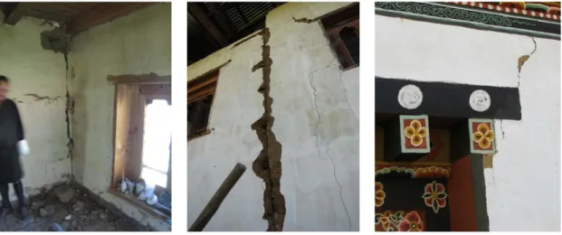
The typical damages observed in RE constructions in the western Bhutan after the 2011 Sikkim-Bhutan earthquake (Figure 9-10) were vertical cracks, separation of walls at the corner, tilting of high walls, diagonal opening cracks and cracks at the connection of timber beams and wall. It should be noted that some of the damaged houses had two storeys and 80-100cm thick walls. (Bhutan, 2011)
(a) (b) (c)
Figure 9: Typical damages of RE constructions from Bhutan, after the Sikkim-Bhutan earthquake: (a) corner cracks; (b) separation of old and new walls; (c) diagonal cracks at the openings
Seismic strengthening of rammed earth constructions using reinforced coatings
Another type of damage noticed was displacement of rabsey, (Figure 10 (a)), a full height window at upper floors which is anchored in the walls preventing out of plane movement. Some places were not anchored, were just resting with the weight (Bhutan, 2011).
(a) (b) (c)
Figure 10: Typical damages of RE constructions (a) Separation of corner walls; (b) vertical wall cracks and (c) corner failure
In Alentejo, southern Portugal, the traditional RE house generally presents a simple and rectangular plan and has only one floor. The thickness of the walls is usually 50cm, increasing only in the case of taller buildings. The wall’s footing is in stone masonry, with 30 to 50cm height and with the same thickness of the walls. To improve the mechanical behaviour, the soil can be stabilized with the addition of lime, cement or both (Parreira, n.d.).
Many earthquake resistant designs have been used to reinforce and retrofit and improve the seismic performance of earth constructions. Research from Latin American countries, in the last 20 years, found several parameters influencing earth construction- soil particle size distribution, humidity content, compaction level, use of natural additives, joint treatment etc. Presence of clay in soils is fundamental to have strong walls, since clay provides the dry strength. The addition of 0.25 to 0.5% of straw (5cm length) may help improving the control of micro-cracking in the walls, but it does not prevent the formation of vertical drying cracks. The RE walls can also be reinforced with high tension materials, such as canes or other timber elements placed as a mesh at the surfaces of the wall, whose objective is to improve the in-plane and out-of-in-plane behaviour (Vargas, n.d.). Good seismic design should have adequate research on material properties and also follow basic design concepts. Minke (2001) presents principles on construction of earthquake resistant houses made of earth, which are here also discussed.
The impact of earthquake depends not only on the magnitude but also on the depth and distance from the epicentre, geology and topography of the local of construction. Horizontal forces create more impact on the buildings than the vertical forces. During an earthquake, out-of-plane inertial forces are generated in the walls, which can be damaged or cause total
Seismic strengthening of rammed earth constructions using reinforced coatings
Erasmus Mundus Programme
16 ADVANCED MASTERS IN STRUCTURAL ANALYSIS OF MONUMENTS AND HISTORICAL CONSTRUCTIONS
Furthermore, slender walls can also collapse due to buckling. In-plane inertial forces are also generated, but the associated collapse mechanisms are not as dangerous, since the thrust produced just causes diagonal cracks in poor construction. So in designing, the horizontal force is to be calculated as proportional to the mass of the structure and consider displacements increase with the increased height.
The main aim in earthquake resistant houses is to resist horizontal movements with ductile behaviour and good connections to prevent collapse. The quality of earthquake resistant structure is expressed with the formula ‘structural quality = resistance x ductility’, meaning that the higher are both parameters the higher is the structural quality. However, low resistance structures are expected to be more flexible and vice versa (Grohmann, 1998). For example, in Mendoza and Argentina thick inflexible historic RE walls have high resistance to earthquake while modern slender adobe or bricks have collapsed in moderate seismic actions. There are certain possibilities within the construction, either build rigid massive RE walls with interconnected walls and roofs so that no deformation occurs or use large adobes or a flexible timber framework filled with earth, like the wattle-and-daub technique (Figure 11). In the latter case roof should be connected to the columns separated from walls to have independent movements and flexible walls should dissipate the kinetic energy by absorbing the vibrations with deflections.
Figure 11: Wattle-and-daub structure that survived after a heavy earthquake in Guatemala (Minke, 2001)
2.3 Principles for earthquake resistant houses
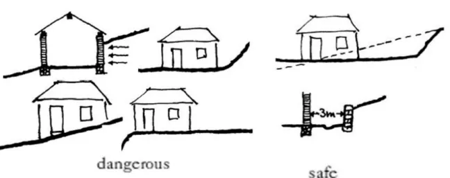
Placement - In earthquake prone areas, houses should not stand on a slope. The structure should be placed over a platform with adequate distance from the slope and marshy ground (Figure 12). For earthen structures to perform well in earthquake, the ideal thickness of the wall is 30 cm and the height should be upto 8 times the thickness of the wall. Higher walls should be supported with buttresses or thickness must be increased. Soil should have adequate amount of clay, coarse, and fine gravel for stability to prevent shrinkage.
Seismic strengthening of rammed earth constructions using reinforced coatings
Figure 12: Dangerous and optimal placement of house on a slope; modified (Minke & Schmidt, 2015)
House shape form - The stability against earthquakes is effected by the shape of the plan, which should be as symmetric, regular and as compact as possible to have a uniform performance. Mass and stiffness should be uniformly distributed. The best plan consists of a circular shape, while L-shape is not very stable (Figure 13). Long shapes should be compacted and divided into parts with flexible connections.
Figure 13: Seismic performance of different plan shapes used for earth construction (Minke & Schmidt, 2015)
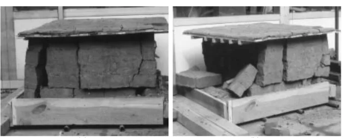
An experimental research, at the University of Kassel, was done to assess the seismic behaviour of different plan shapes, where house models with RE walls were tested stroking the model with certain weight. Results are shown in the Figure 14 and 15. The similar technique with convex walls were used in Afghanistan but openings reduced the stability of the structure as stated by Minke (2001).
Seismic strengthening of rammed earth constructions using reinforced coatings
Erasmus Mundus Programme
18 ADVANCED MASTERS IN STRUCTURAL ANALYSIS OF MONUMENTS AND HISTORICAL CONSTRUCTIONS
(a) (b)
Figure 14: RE model with square plan developed a large crack after the 2nd stroke, (a) one
part separated after 3rd strokes and (b) collapse after 4th stroke (Minke, 2001)
(a) (b)
Figure 15: Circular RE models (a) first crack appeared only after 3rd stroke and (b) after 6th
stroke a small part was separated (Minke, 2001)
In traditional RE, earthquake resistance is dictated by its stiffness and mass. RE constructions are found to be from 60 to 100 cm thick and are not too high. This process of making massive RE walls is no longer used as it is very labour intensive. Modern solutions to stabilize RE walls have been used recently. Elements of shape L, T, U, X, Y or Z have shown better stability against lateral forces due to their angles. In 30cm thick walls, free ends should not be longer than 3/4 and not shorter than 1/3 of the height. The perpendicular forces are transferred through the angle connection to the parallel walls and creates a stress concentration at the inner corner. Therefore, this section should be flexible, designed and connected well (with ties) in order to transfer the forces (Figure 16). The thickness of adobe, brick or RE walls should be at least 1/8 of its height.
Seismic strengthening of rammed earth constructions using reinforced coatings
(a) (b)
Figure 16: Recommended proportions for earth walls (a) for the free ends and (b) corner extension for the connection (Minke, 2001)
Another method for strengthening RE walls against seismic action is by means of internal reinforcements with vertical rods embedded in the walls. Bamboo, wood or cane rods can be used for this purpose. These vertical elements should be embedded inside the walls and fixed to the foundation and the ring beam (Figure 17). Bond between foundation-plinth and plinth-wall should be good, this can be done by integrating a wooden or bamboo rod of 2.5 to 5 cm at every 40 to 50 cm (Minke, 2001).
To absorb horizontal shocks from an earthquake a floating foundation can also be done with two or three layers of plastic bags filled with pebbles. The foundation should be 10 cm wider than the plinth on each side and should be at least 40 cm deep. Horizontal reinforcing elements are not used normally, since the bond with the earthen material is poor, whereby the shear forces are not transmitted properly. It is also difficult to ram the earth below these elements because of its elastic behaviour (Minke, 2001).
(a) (b) (c)
Seismic strengthening of rammed earth constructions using reinforced coatings
Erasmus Mundus Programme
20 ADVANCED MASTERS IN STRUCTURAL ANALYSIS OF MONUMENTS AND HISTORICAL CONSTRUCTIONS
beam on top and bottom (c) floating foundation with plastic bags filled with pebbles (Minke, 2001)
Surveys after earthquakes found some typical design faults in South America which led to collapse of rural houses. These faults include lack of a ring beams, inadequate lintel thickness and shape of windows. Lintels should be avoided and high windows reaching up till the ring beam can be used. Connection between the ring beam and the wall should be strong to prevent buckling. The ring beam is expected to hold the wall and can be made of reinforced concrete, wood or bamboo (Figure 18). The connection should be sufficiently stiff at the corner. In case of adobe and post-beam framework, there must be a good connection between the posts and the adobe, as adobe will fall with horizontal vibrations of the earthquake. External ring beam is also possible with supporting it on pillars with strong interconnection at the corners. The roof must also be connected to the ring beam. The openings for windows and doors should be no more than 1 m wide. Mortar joints should not be thicker than 1.27cm between the bricks. RE constructions in seismic areas must give priority to shear strength and ductility provided by compatible materials such as cane and wood.
(a) (b) (c) Figure 18:Possibilities of fixing wooden ring beams (a) wooden beams in RE wall; (b) vertical
post fixed to a double ring beam in RE wall and (c) adobe walls reinforced by buttresses and ring beams on the top of the walls (Minke & Schmidt, 2015)
2.4 Reinforced coatings
In the field of seismic retrofitting of adobe masonry structures, reinforced coatings have proved to improve greatly the structural performance. Several laboratory experiments simulating earthquakes vibrations on full scale adobe models were done at Catholic University of Peru (PCUP) in the last decades. The studies evaluated the feasibility of strengthening adobe building using ‘geomeshes’ (plastic or metallic). The reinforcement walls showed improvement in ductility and withstood a maximum lateral drift of 5.18 %, double than that of the unreinforced model. Similar experimental researches were carried out in Mexico on retrofitting with