BJRS
RADIATION SCIENCES
06-02 (2018) 01-14Accepted for publication: 2018-04-17
Effect of the skyshine approach on the total cost of
concrete shielding in a conventional radiotherapy
facility room
Eduardo de Paiva
Instituto de Radioproteção e Dosimetria/Divisão de Física Médica, 22783-127, Rio de Janeiro, Rio de Janeiro, Brazil [email protected]
ABSTRACT
Photon beams produced in large linear accelerators are widely used in medicine for the treatment of cancer. Nevertheless, the use of these medical purpose machines in radiotherapy bring some interesting questions as for example how to evaluate the thicknesses of the walls of the facility room housing them in order to guarantee that their vicinities do not receive a radiation dose above the permissible levels. The aim of this work is to present a simplified general formalism for the estimation of wall thicknesses of a facility room housing linear accelerators that generate photons with energies in the range 4-30 MeV and using ordinary concrete as the material of shield-ing. A computer code based on FORTRAN programming language was developed in order to handle with all the input parameters. The roof thickness was calculated according to the skyshine approach, and the overall results have shown a lower total volume and associated cost of concrete shielding as compared with the primary ap-proach.
1. INTRODUCTION
Photon radiation produced by large electron linear accelerators (linacs) are widely used in radio-therapy for the treatment of cancer. These clinical machines can produce photon beams of high en-ergies varying from 4 up to 30 MeV. These therapeutic photon beams are of special importance in external beam radiation therapy due to the increasing number of cases of cancer; according to the World Cancer Research Fund International there are expected 24 million of cancer cases by the year of 2035 (52% of cases in men, 48% in women) [1]. Nevertheless, the use of high-energy linear ac-celerators in radiation therapy imposes a question that is how to estimate the thicknesses of the bar-riers of the facility room housing the machines so as to prevent that its vicinity does not receive doses of ionizing radiation above the desirable levels.
In this work a detailed investigation of the thicknesses of the barriers of a conventional facility room housing linear accelerators producing high-energy photon beams with single endpoint ener-gies of 4, 6, 8, 10, 12, 15, 18, 20, 25 and 30 MV and the associated costs using ordinary concrete as the material of shielding are performed. We carry out calculations for a standard facility room de-picted in Figures 1 to 3 at three values of total workloads that are 800, 1,000 and 1,200 Gy/week; no special procedures such as intensity modulated radiation therapy (IMRT), stereotactic radiosurgery (SRS), and total-body radiation (TBI), nor modern treatment devices are considered in this work. A routine calculation was developed using FORTRAN programming language, which allows us to estimate all the thicknesses of the facility room for all set of input parameters. Results can be used to estimate the amount of additional shielding when an upgrade to a higher-energy machine is made. In a companion paper a general description of the calculation method was made in which the roof thickness was estimated in the same way as for the vertical barriers [2]. Now, in this work we focus on an alternative way to evaluate the roof thickness that is the skyshine approach. When a sheltered photon source irradiates vertically up, the air above the roof can scatters the radiation back to the ground level reaching locations outside the facility room barriers. This stray radiation is termed skyshine and can be a serious source of hazard for workers as well as for members of the public.
2. MATERIALS AND METHODS
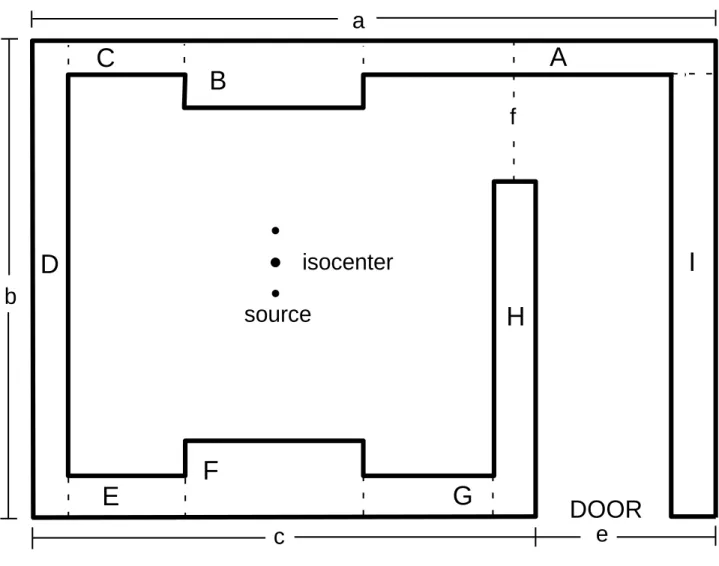
Figure 1 shows the radiotherapy facility room used in this study. The room has area a × b; c is the central width of the room where the machine is located; e is the width of the door plus the thick-ness of wall I; f is the distance from the end of wall H to the external side of wall A, and for all en-ergies the isocenter is at (c/2, b/2). The walls B and F are primary barriers (barriers that intercept radiation emitted directly from the source), and the remaining are secondary barriers (barriers that intercept radiation scattered from the patient and other media, and radiation that escapes from the
Figure 1. The floor plan of the radiotherapy facility room used throughout calculations.
A
B
C
D
E
F
G
H
I
DOOR
a
b
c
e
f
source
isocenter
accelerator head). The facility room has a constant height h and the source or target is at a fixed distance h0 from the ground when the gantry is pointed to the roof.
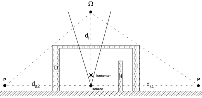
The roof thickness can be calculated taking into consideration the primary radiation beam when the gantry is directed upward, and the secondary leakage and scattered radiation in the same way as described in a companion paper for the vertical barriers [2], although another possibility exists as follows. An interesting situation occurs when there is no occupancy above the ceiling and no build-ings in the vicinity of the room. In this case the photon radiation can be scattered in the air layers above the ceiling and reaches locations in the external side of the linear accelerator facility room (see Figures 2 and 3), being a source of hazard for workers as well as for members of the public. This kind of stray radiation is known as skyshine and the coefficient of the transmission through the barrier is given by [3, 4]
(
)
. . 10 5 . 2 1 3 . 1 0 2 2 = − D d d P B i s sky (1)In Equation (1) di is the distance from the source to a point two meters above the roof; ds is the hor-izontal distance from the source to the point of observation outside the room; D0 is the x-ray ab-sorbed-dose output rate, and Ω is the solid angle subtended by the beam [5].
In order to implement the skyshine calculation we need to define the distances (in meters):
- dT is the distance from the source to the point to be protected beyond barrier T (roof) with the beam directed vertically up.
𝑑𝑇 = ℎ − ℎ0.
- di is the distance from the source to a point 2 meters above the roof. 𝑑𝑖= 𝑑𝑇+ 2.
- ds1 is the horizontal distance from the source to the point of interest behind wall I. 𝑑𝑠1= (
𝑑𝑇+ 2
2 ) (
𝑐 2+ 𝑒).
Figure 2. The geometry used in the skyshine calculation of the roof thickness. Photon radiation reaches points P in the external side of walls I and D.
Figure 3. The geometry used in the skyshine calculation of the roof thickness. Photon radiation reaches points P in the external side of walls F and B.
𝑑𝑠2= ( 𝑑𝑇+ 2 2 ) ( 𝑐 2).
d
i ds1
source Isocenter P D I H Pd
s2d
i ds3
source Isocenter P B F Pd
s3- ds3 is the horizontal distance from the source to the point of interest behind wall B or F. 𝑑𝑠3= ( 𝑑𝑇+ 2 2 ) ( 𝑏 2).
In calculation of the volume of concrete shielding of the roof the greater thickness among the three obtained is used, which is, off course, a conservative approach. Note that in our model the volume is not only 𝑡𝑠𝑘𝑦× 𝑎 × 𝑏, but the correspondent fractions of volumes due to walls A, B, C, D, E, F, G, I and H must be subtracted from it, since the room walls can only increase to its interior. A routine calculation was developed using FORTRAN language and the code is based on six sub-routines, as summarized in the companion paper [2]. The fifth subroutine is used to determine the roof thickness due to the contribution only from skyshine radiation according to Equation (1). The sixth subroutine is used to choose the greater thickness among the three thicknesses obtained from skyshine procedure if the horizontal distances ds1, ds2 or ds3 are used as input (see Figures 2 and 3).
3. RESULTS AND DISCUSSION
In the hypothesis that there is no occupancy in the region above the roof, the skyshine procedure can be used. For the skyshine radiation, the permissible dose rate level at the point of observation is assumed to be equal to the value of uncontrolled area [6], and the field size at the patient (isocenter) is constant and equal to 40 × 40 cm2. The x-ray absorbed-dose output rate can be as low as 5 cGy/min for machines that have the low dose rate option, and on the other hand it can be as high as some thousands of cGy/min for certain configurations dedicated to more complex treatment tech-niques. For the aim of this work, we use a typical and somewhat high value for conventional radio-therapy of 800 cGy/min for all energies throughout calculations. In this study we consider linear accelerators with single energies 4, 6, 8, 10, 12, 15, 18, 20, 25 and 30 MeV. The thickness and vol-ume of each wall and the total cost of common concrete (2.35 g/cm3) shielding of the facility room
were calculated for each energy and for the workloads, 800, 1,000 and 1,200 Gy/week. The price of one cubic meter of ordinary concrete varies from region to region, so along all estimations an option was done to take it arbitrarily as US$ 100. From the results presented here and with this approach, readers can easily obtain the total costs for any value of cubic meter of concrete. In Figures 4 to 6
the parameters a, b, e, f, h and h0 have the values: a = 15, b = 11, e = f = 2.5, h = 5.7 and h0 = 0.4 meters.
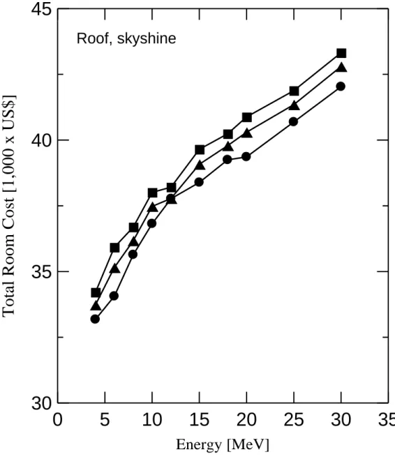
In Figure 4 we present the total cost of the room (in thousands of dollars) of concrete shielding as a function of the energy of the beam considering the skyshine approach for the roof thickness calculation. The total cost varies from US$ 33,180 at 4 MV to US$ 42,030 at 30 MV for the 800 Gy/week workload; US$ 33,730 at 4 MV to US$ 42,800 at 30 MV for the 1,000 Gy/week work-load, and US$ 34,210 at 4 MV to US$ 43,320 at 30 MV for the 1,200 Gy/week workwork-load, repre-senting a difference about 27% between the minimum and maximum energy to each workload. Re-sults also indicate an overall difference in total cost among workloads of less than 4%.
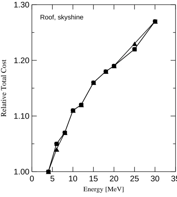
In Figure 5 the results of total cost of the room of concrete shielding obtained from the skyshine procedure for the roof are presented relative to the 4 MV cost for the 800, 1,000 and 1,200 Gy/week. Once again, we can see that results are quite independent of the workload and for the three workloads the total shielding at 30 MV are 27% greater than at 4 MV.
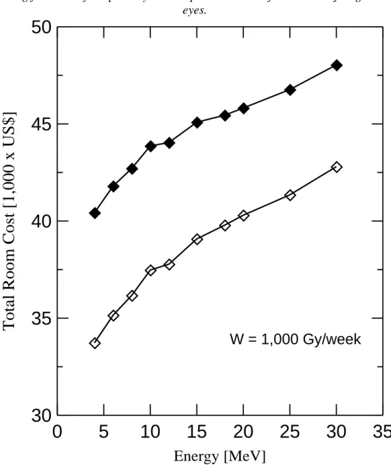
Figure 6 shows the total cost of concrete shielding as a function of the energy of the beam at a fixed workload of 1,000 Gy/week. For the sake of comparison, both procedures of primary (top, described in the companion work [2]) and skyshine (bottom) are presented for the roof. Once again, results have indicated an increase of total cost with beam energy for both approaches. The maxi-mum differences between the two approaches are of the order of 20%.
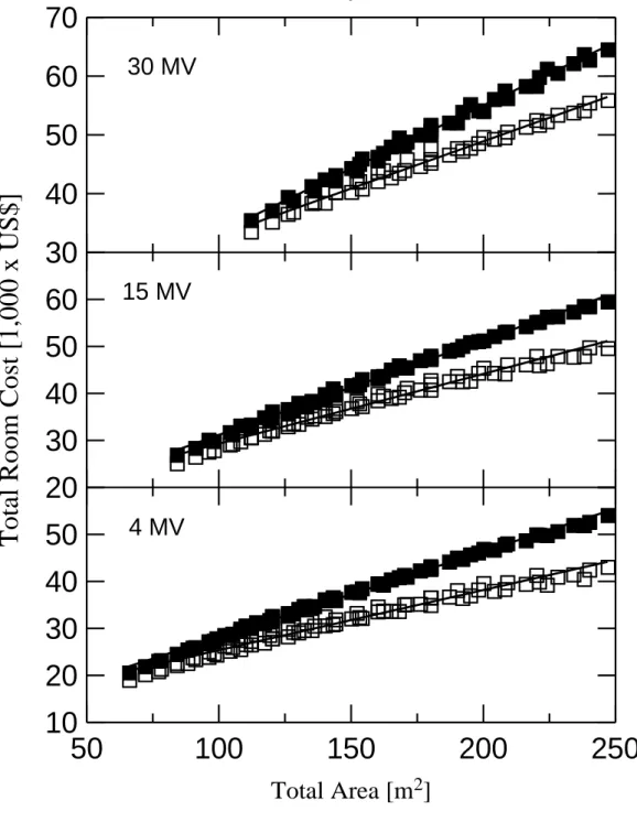
Figure 7 shows the total cost in thousands of dollars of concrete shielding for a 4 MV (bottom scale), 15 MV (middle scale) and 30 MV (top scale) linac as a function of the total available area at1,000 Gy/week workload. The parameters e, f, h and h0 have the same values as before, and
Figure 4. The total cost (in thousands of dollars) of concrete shielding as a function of the energy of the beam. The roof thickness is calculated according to the skyshine procedure. Circles, triangles
and squares are results respectively for 800, 1,000 and 1,200 Gy/week workloads; the full lines are just guides to the eyes.
0
5
10
15
20
25
30
35
Energy [MeV]
30
35
40
45
T
o
ta
l
R
o
o
m
C
o
st
[
1
,0
0
0
x
U
S
$
]
Roof, skyshine
Figure 5. The total cost of concrete shielding as a function of the energy of the beam. Results are normalized to the 4 MeV energy and the roof is calculated according to the skyshine procedure.
Circles, triangles and squares are results respectively for 800, 1,000 and 1,200 Gy/week work-loads; the full lines are just guides to the eyes.
0
5
10
15
20
25
30
35
Energy [MeV]
1.00
1.10
1.20
1.30
R
el
at
iv
e
T
o
ta
l
C
o
st
Roof, skyshine
Figure 6: The total cost (in thousands of dollars) of concrete shielding as a function of the energy of the beam at the fixed workload of 1,000 Gy/week. Empty lozenges are results cal-culated considering for the roof the skyshine procedure, full lozenges are results calcal-culated
considering for the roof the primary barrier procedure. The full lines are just guides to the eyes.
0
5
10
15
20
25
30
35
Energy [MeV]
30
35
40
45
50
T
o
ta
l
R
o
o
m
C
o
st
[
1
,0
0
0
x
U
S
$
]
W = 1,000 Gy/week
Figure 7: The total cost (in thousands of dollars) of concrete shielding plotted against the available area to build the facility room. Results are shown for a 4, 15 and 30 MV linac at the fixed workload of 1,000 Gy/week. Empty squares are results calculated considering for the roof the skyshine pro-cedure, and full squares are results calculated considering for the roof the primary barrier
proce-dure. The solid lines are linear fits to the data.
50
100
150
200
250
Total Area [m
2]
10
20
30
40
50
20
30
40
50
60
T
o
ta
l
R
o
o
m
C
o
st
[
1
,0
0
0
x
U
S
$
]
30
40
50
60
70
30 MV
15 MV
4 MV
11 ≤ a ≤ 20 and 6 ≤ b ≤ 14 in meters. For the sake of comparison, in each part of Figure 7 are also shown the results obtained from the primary procedure for the roof (upper data, obtained in the companion work [2]). Because of the limiting conditions previously mentioned, the minimum area necessary to construct the room ranges from ~65 m2 to the 4 MV up to ~110 m2 to the 30 MV linac. For the range of areas analyzed results have shown that the cost of using the primary procedure dif-fers from the skyshine procedure by a minimum amount of ~8% up to a maximum value of ~28% to the 4 MV linac; a minimum value of ~6% up to a maximum of ~22% to the 15 MV linac, and to the 30 MV linac it ranges from ~4% up to ~18%. It can clearly be seen a tendency of linear increases of the total cost of concrete shielding with the increasing of total available area for both primary and skyshine procedure. In countries or regions where the use of the skyshine procedure can be adopted, NCRP Report No. 151 [6] recommends that Equation (1) should be used with caution for the evalu-ation of the roof thickness or the dose outside the facility room.
Measurements of radiation skyshine doses from an 18 MV [7] and a 6 MV [8] clinical linear ac-celerators have shown inconsistencies with the results calculated from Equation (1), mainly at large horizontal distances from the isocenter. In both work the measurements were performed considering the maximum 40 cm x 40 cm field size at the isocenter and a fixed x-ray output rate of 6.67 cGy/s at one meter from the target. The measured dose rates have shown an increase as the horizontal dis-tance from the vertical wall increases, then reaching a maximum value at ~13.6 m (18 MV beam) and ~7.2 m (6 MV x-ray beam) from the source, and from these maximum distances on the dose rates begin to decrease. These data have a remarkably different behavior as compared with the re-sults calculated from Equation (1) (solved to give the dose rate at distance ds) that always decrease with the increasing of distance from the target. The disagreement between measured and calculated values varies drastically from -75% at 7.5 m up to 430% at 48 m for the 18 MV x-ray beam, and -82% at 4.5 m up to 109% at 18 m for the 6 MV x-ray beam.
A reasonable agreement between measured and calculated photon skyshine doses occur only at a few distances from the isocenter. According to the results reported in these two papers it can be seen that in general the calculations obtained by means of Equation (1) underestimate the measure-ments. For that reason, a more complete set of measurements encompassing various energies is needed to a better understanding of the radiation skyshine phenomenon in the vicinities of radio-therapy rooms, and the calculations can be used as guide to study the radiation skyshine.
4. CONCLUSION
Two approaches can be used to estimate the roof thickness of radiotherapy rooms housing med-ical purpose linacs. First, calculating it in the same way as it is made to the lateral primary and sec-ondary barriers; and second considering the special procedure of skyshine when there is no occu-pancy above the roof and no building in its vicinity. Results have shown a lower total cost of con-crete shielding of the skyshine procedure as compared with the primary one. Nevertheless, despite the lower total concrete cost of the room when using the skyshine approach, caution must be taken if there is a possibility of future occupancy of the area above the roof or arising of new buildings near the facility room. Therefore, the results presented here can serve as a guide for users in the study of thicknesses, volumes and costs when using common concrete in shielding of radiotherapy facilities rooms that use medical purpose linear accelerators. This work can either serve to estimate the additional shielding in an existing room when an upgrade to a higher-energy linac is planned. As pointed out in the companion paper, the next step in this study is the evaluation of the impact on total cost of inclusion of the door shielding and also considering modern and more complex treat-ment techniques.
REFERENCES
[1] WCRF - World Cancer Research Fund International. Available at:
<http://www.wcrf.org/int/cancer-facts-figures/worldwide-data>. Last accessed: 15 Jan. 2018.
[2] DE PAIVA, E. A study on the cost of concrete shielding in a standard radiotherapy facility room. Braz J Rad Sciences, v. 6, p. xx-xx, 2018.
[3] NCRP - National Council on Radiation Protection and Measurements. Radiation protection
design guidelines for 0.1-100 MeV particle accelerator facilities. NCRP Report 51,
Washing-ton: NCRP, 1977. 160p.
[4] NCRP - National Council on Radiation Protection and Measurements. Structural shielding
design and evaluation for megavoltage X- and gamma-ray radiotherapy facilities. NCRP Re-port 151, Bethesda: NCRP, 2005. 246p.
[5] GOSSMAN, M. S.; PAHIKKALA, A. J.; RISING, M. B.; MCGINLEY, P. H. Providing solid angle formalism for skyshine calculations. J Appl Clin Med Physics, v. 11, p. 278-282, 2010. [6] CNEN - Comissão Nacional de Energia Nuclear. Diretrizes básicas de proteção radiológica.
CNEN-NN-3.01, Rio de Janeiro: CNEN, 2005. 21p.
[7] MCGINLEY, P. H. Radiation skyshine produced by an 18 MeV medical accelerator. Rad Prot
Mgmt, v. 10, p. 59-64, 1993.
[8] GOSSMAN, M. S.; MCGINLEY P. H.; RISING M. B.; PAHIKKALA A. J. Radiation skyshine from a 6 MeV medical accelerator. J Appl Clin Med Physics, v. 11, p. 259-264, 2010.