2018
UNIVERSIDADE DE LISBOA FACULDADE DE CIÊNCIAS DEPARTAMENTO DE INFORMÁTICA
Resilient Communications in Smart Grids
Pedro Alexandre Pacheco Pinto Maia
Mestrado em Segurança Informática
Dissertação orientada por:
Prof. Doutor Nuno Fuentecilla Maia Ferreira Neves
Prof. Doutor Fernando Manuel Valente Ramos
Acknowledgments
I am grateful to all the persons and entities that helped me throughout this long jour-ney.
I would especially like to thank my instructors Dr. Nuno Neves and Dr. Fernando Ramos for guiding me and also for the time and knowledge that helped me fulfil this work. I also would like to thank Ricardo Fonseca for all the help and support that he gave me. To my family of course, this wouldn’t be possible without you. Thank you for all the support that all of you gave during all this years.
Also would like to thank the project FP7 SEGRID (607109) for the funding that made this possible.
And last but not least to Vanessa for pushing me and keeping me on track when i even slightly steer out of it. Especially without you this wouldn’t be possible.
As redes el´etricas, algumas j´a centen´arias, foram concebidas para uma realidade bas-tante diferente da actual. O facto de terem sido desenhadas para transportar e distribuir a energia de forma unidirecional, torna a infraestrutura r´ıgida, causando problemas em termos de escalabilidade e dificulta a sua evoluc¸˜ao.
Conhecidas quest˜oes ambientais tˆem levado a que a gerac¸˜ao de energia baseada em combust´ıveis fosseis seja substitu´ıda pela gerac¸˜ao atrav´es de fontes de energia renov´aveis. Esta situac¸˜ao motivou a criac¸˜ao de incentivos ao investimento nas fontes de energia re-nov´aveis, o que levou a que cada vez mais consumidores apostem na microgerac¸˜ao. Es-tas alterac¸˜oes causaram uma mudanc¸a na forma como ´e feita a produc¸˜ao e distribuic¸˜ao de energia el´etrica, com uma aposta crescente na interligac¸˜ao entre as v´arias fontes ao longo da infraestrutura, tornando a gest˜ao destas redes uma tarefa extremamente com-plexa. Com o crescimento significativo de consumidores que tamb´em podem ser produ-tores, torna-se essencial uma coordenac¸˜ao cuidada na injec¸˜ao de energia na rede. Este facto, aliado `a crescente utilizac¸˜ao de energia el´etrica, faz com que a manutenc¸˜ao da es-tabilidade da rede seja um enorme desafio.
As redes inteligentes, ou smart grids, prop˜oem resolver muitos dos problemas que surgiram com esta alterac¸˜ao do paradigma de consumo/produc¸˜ao de energia el´etrica. Os componentes da rede passam a comunicar uns com os outros, tornando a rede el´etrica bidirecional, facilitando assim a sua manutenc¸˜ao e gest˜ao. A possibilidade de constante troca de informac¸˜ao entre todos os componentes que constituem a smart grid permite uma reac¸˜ao imediata relativamente `as ac¸˜oes dos produtores e consumidores de energia el´etrica. No entanto, com esta alterac¸˜ao de paradigma surgiram tamb´em muitos desafios.
Nomeadamente, a necessidade de comunicac¸˜ao entre os equipamentos existentes nas smart grids leva a que as redes de comunicac¸˜ao tenham de cobrir grandes ´areas. Essa com-plexidade aumenta quando a gest˜ao necessita de ser feita ao n´ıvel de cada equipamento e n˜ao de forma global. Isto ´e devido ao facto de nas redes de comunicac¸˜ao tradicionais, o plano de controlo e o de dados estarem no mesmo equipamento, o que leva a que o seu controlo seja dif´ıcil e prop´ıcio a erros. Este controlo descentralizado dificulta tamb´em a reorganizac¸˜ao da rede quando ocorrem faltas pelo facto de n˜ao existir um dispositivo que
tenha o conhecimento completo da rede. A adaptac¸˜ao r´apida a faltas de forma a tornar a comunicac¸˜ao resiliente tem grande importˆancia em redes sens´ıveis a latˆencia como ´e o caso da smart grid, pelo que mecanismos eficientes de tolerˆancia a faltas devem ser implementados.
As redes definidas por software, ou Software Defined Networks (SDN), surgem como uma potencial soluc¸˜ao para estes problemas. Atrav´es da separac¸˜ao entre o plano de con-trolo e o plano de dados, permite a centralizac¸˜ao l´ogica do concon-trolo da rede no controlador. Para tal, ´e necess´ario adicionar uma camada de comunicac¸˜ao entre o controlador e os dis-positivos de rede, atrav´es de um protocolo como o Openflow. Esta separac¸˜ao reduz a complexidade da gest˜ao da rede e a centralizac¸˜ao l´ogica torna poss´ıvel programar a rede de forma global, de modo a aplicar as pol´ıticas pretendidas. Estes fatores tornam a SDN uma soluc¸˜ao interessante para utilizar em smart grids.
Esta tese investiga formas de tornar a rede de comunicac¸˜oes empregue numa smart grid resiliente a faltas. Pelas vantagens mencionadas anteriormente, ´e usada uma soluc¸˜ao baseada em SDN, sendo propostos dois m´odulos essenciais. O primeiro tem como ob-jectivo a monitorizac¸˜ao segura da rede, permitindo obter em tempo real m´etricas como largura de banda, latˆencia e taxa de erro. O segundo m´odulo trata do roteamento e en-genharia de tr´afego, utilizando a informac¸˜ao fornecida pelo m´odulo de monitorizac¸˜ao de forma a que os componentes da smart grid comuniquem entre si, garantindo que os re-quisitos das aplicac¸˜oes s˜ao cumpridos. Dada a criticidade da rede el´etrica e a importˆancia das comunicac¸˜oes na smart grid, os mecanismos desenvolvidos toleram faltas, quer de tipo malicioso, quer de tipo acidental.
Palavras-chave: Smart Grid, resiliente, SDN, monitorizac¸˜ao, roteamento, engenharia de tr´afego
Abstract
The evolution on how electricity is produced and consumed has made the manage-ment of power grids an extremely complex task. Today’s centenary power grids were not designed to fit a new reality where consumers can also be producers, or the impressive increase in consumption caused by more sophisticated and powerful appliances. Smart Grids have been prepared as a solution to cope with this problem, by supporting more so-phisticated communications among all the components, allowing the grid to react quickly to changes in both consumption or production of energy. On the other hand, resorting to information and communication technologies (ICT) brings some challenges, namely, managing network devices at this scale and assuring that the strict communication re-quirements are fulfilled is a dauting task.
Software Defined Networks (SDN) can address some of these problems by separat-ing the control and data planes, and logically centralizseparat-ing network control in a controller. The centralised control has the ability to observe the current state of the network from a vantage point, and programatically react based on that view, making the management task substantially easier.
In this thesis we provide a solution for a resilient communications network for Smart Grids based on SDN. As Smart Grids are very sensitive to network issues, such as latency and packet loss, it is important to detect and react to any fault in a timely manner. To achieve this we propose and develop two core modules, a network monitor and a routing and traffic engineering module. The first is a solution for monitoring with the goal to obtain a global view of the current state of the network. The solution is secure, allowing malicious attempts to subvert this module to be detected in a timely manner. This infor-mation is then used by the second module to make routing decisions. The routing and traffic engineering module ensures that the communications among the smart grid com-ponents are possible and fulfils the strict requirements of the Smart Grid.
Keywords: Smart Grid, resilient network, SDN, network monitoring, routing, traffic engineering
Contents
List of Figures xi
1 Introduction 1
1.1 Smart grid . . . 1
1.2 Motivation . . . 2
1.3 Conventional communications networks . . . 2
1.4 Software Defined Networks as an Alternative . . . 3
1.5 Objectives . . . 4
1.6 Contributions . . . 4
1.7 Document Structure . . . 5
2 Related Work 7 2.1 Software Defined Network . . . 7
2.1.1 Architecture . . . 8 2.1.2 Openflow . . . 9 2.1.3 SDN Controller . . . 9 2.2 Network Routing . . . 11 2.3 Traffic Engineering . . . 12 2.3.1 Traditional Networks TE . . . 12
2.3.2 Software Defined Networks TE . . . 13
2.4 Network Monitoring . . . 13
2.4.1 Simple Network Management Protocol . . . 13
2.4.2 Active Probing . . . 14 2.4.3 Packet Sampling . . . 14 2.4.4 SDN Monitoring . . . 15 2.5 Tools . . . 16 2.5.1 Mininet . . . 16 2.5.2 Scapy . . . 17 2.5.3 Iperf . . . 17 vii
3.1.1 Generic adversary capabilities . . . 19
3.1.2 Attacks on latency estimation . . . 20
3.1.3 Attacks on throughput estimation . . . 22
3.2 Threat model . . . 23
3.3 Monitoring . . . 23
3.3.1 Control plane latency . . . 24
3.3.2 Throughput . . . 25
3.3.3 Sampling . . . 25
3.3.4 Loss Rate . . . 26
3.3.5 Monitoring API . . . 26
3.4 Traffic Engineering . . . 27
3.4.1 Smart Grid Requirements . . . 27
3.4.2 Network Graph . . . 27 3.4.3 Resilient Routing . . . 28 3.4.4 Forwarding . . . 30 3.5 Implementation . . . 30 3.5.1 Switch Latency . . . 30 3.5.2 Throughput . . . 31 3.5.3 Sampling . . . 33 3.5.4 Network Graph . . . 39 3.5.5 Resilient Routing . . . 39 3.5.6 Forwarding . . . 39 3.6 Summary . . . 39 4 Evaluation 41 4.1 Test Environment . . . 41 4.2 Monitoring . . . 43
4.2.1 Monitoring startup time . . . 44
4.2.2 Failure detection time . . . 46
4.3 Routing . . . 47
4.4 Summary . . . 49
5 Conclusions 51
List of Figures
1.1 Example smart grid communication networks . . . 1
1.2 Smart Grid Information Flow [1] . . . 3
2.1 General SDN architecture . . . 8
2.2 Openflow Switch [2] . . . 10
3.1 Example of a packet reroute performed by the adversary . . . 20
3.2 Monitoring architecture . . . 24
3.3 Trafic engineering module architecture. . . 27
3.4 Backup route in action . . . 29
3.5 Complex backup route in action . . . 29
3.6 Method to Measure the Latency. . . 31
3.7 Sampling example . . . 36
4.1 Evaluation network . . . 42
4.2 Monitoring startup time at 1Mbps . . . 44
4.3 Monitoring startup time at 10Mbps . . . 45
4.4 Monitoring startup time at 100Mbps . . . 45
4.5 Monitoring startup catch window at 1Mbps . . . 45
4.6 Monitoring startup catch window at 10Mbps . . . 46
4.7 Monitoring startup catch window at 100Mbps . . . 46
4.8 Experiment until detection at 10Mbps and 100Mbps . . . 47
4.9 Time to re-route on failure . . . 48 4.10 Reroute time after a failure on networks with different number of switches. 48
List of Tables
3.1 Sampling configuration parameters description . . . 34 4.1 Configuration parameters value used in evaluation . . . 43
Chapter 1
Introduction
1.1 Smart grid
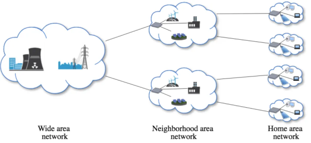
Smart Grids are composed of the various components of the electrical infrastructure in-terconnected by a communications network. In contrast to traditional power grids, Smart Grids are able to cope with the dynamism present in today’s power grids, which results in a reduction of transmission and distribution losses, increased efficiency in the use of renewable energy sources, allowing large scale energy storage and enabling market-based electricity pricing. Smart Grids enable the use of new, intelligent appliances that are ca-pable of deciding when to consume power based on pre-set costumer preferences. This effectively reduces peak loads and the need for new power plants, while maximising the use of renewable energy. By resorting to smart meters and smart substations, distribu-tion system operators are now able to quickly identify problems and dispatch repair crews to the correct location. The constant communication required in a Smart Grid enables self-healing, self-balancing and self-optimizing distribution, allowing the prediction of cable failures based on real-time data about weather and outage history, by using auto-mated monitoring and analysis tools. Generically, it is possible to separate a Smart Grid network in three parts, as in Figure 1.1.
Figure 1.1: Example smart grid communication networks 1
The Home Area Network (HAN) can use several communications technologies, both wired and wireless, and enables the smart management and consumption monitoring of home appliances. The HAN is connected to the Neighborhood Area Network (NAN) through a gateway. The NAN is composed of all the HANs (represented by its gateway), the sub-stations, the distribution systems, distributed power generation and the NAN gate-way. Finally, the Wide Area Network (WAN) connects all NAN gateways, power genera-tion infrastructures, and transmission elements.
1.2 Motivation
Power grids are evolving. The static design of existing electrical infrastructures does not fit the current needs, such as energy production being distributed across a vast area and micro-generation becoming a reality. There is a global demand on the use of renewable energy for environmental protection, which adds new difficulties to power management, as energy generation is not as predictable as in traditional power plants. The need for a dynamic and self-healing infrastructure is growing and smart-grids are the proposed so-lution for this evoso-lution. Smart Grids are composed of multiple components and assets, as shown in Figure 1.2, such as power generation, substations, circuit breakers, sensors, smart meters, etc. These components bring a new set of capabilities to electrical in-frastructures that enable more efficient power delivery and resource usage. To achieve this higher efficiency, these components require the ability to exchange data in order to collect information about their state and then, if necessary, adjust their behaviour. This requirement of continuous data exchange makes the communications network a critical component of Smart Grids [30, 28]. Since the communications network take such an im-portant role in the correct and efficient operation of Smart Grids, making it resilient to faults is crucial.
The communications network inside a substation (in the NAN), where well defined applications typically run, can be made more resilient using traditional techniques (e.g., adding link redundancy). A more challenging problem is enhancing the resilience of the network that interconnects all substations and the control center (the WAN). This network spreads over a large geographical area, and some parts of it may be owned by a telecommunications provider. Due to its scale, such network can be more prone to accidental problems and attacks, requiring advanced solutions to address the uncertainty of the network state. Our work is focused on this particular part of the network: the WAN.
1.3 Conventional communications networks
In conventional communication networks, such as those typically used in traditional grids, the control and packet data planes are bundled together in the same device. In other words,
Chapter 1. Introduction 3
Figure 1.2: Smart Grid Information Flow [1]
the switches and routers deal with two problems: 1) forward packets, and 2) decide how to forward packets. This property makes networks complex to manage and control. Re-searchers and practitioners have been arguing that this complexity indeed derives from the integration of control functionality in devices that should only be responsible for for-warding packets [37]. Adding to the challenge, Smart Grids run applications with strict requirements, including maximum limits on latency and packet loss. Fulfilling these re-quirements, entails sophisticated algorithms to be executed in the control plane of each device, increasing the configuration complexity and therefore the probability of errors occurring. These issues mainly derive from the fact that the control plane is decentral-ized. This means that if multiple components of the network need to agree on a given action, they must run a distributed algorithm, sharing their current view of the network in order to get the required result. These algorithms increase the necessary complexity and computing power, leading to greater costs since more expensive hardware is required.
1.4 Software Defined Networks as an Alternative
Software Defined Networks (SDN) have been proposed as a solution to this problem. By decoupling the data plane from the control plane, and logically centralizing the control plane in a controller, many of the issues that affect conventional networks are mitigated. At the data plane, the devices are only responsible for forwarding packets, generating events when changes occur, and keep the record of simple statistics (such as packet & byte counting). This is specially important in large networks such as the ones in Smart Grids. The control plane now sits in a logically centralized controller, which typically runs in a cluster of high end servers being responsible for all the complex tasks, such as maintaining the network topology, routing decisions, recovering from failures, access control, etc. With the aid of the dataplane devices, the controller builds a global view of the network, making the computation of all those functions more efficient and
effec-tive. Another advantage of SDN is the fact that this shift in the control logic promotes openness, removing existing constrains set by current network equipment, allowing the programmatic configuration of the network, facilitating the management and optimization of network resources dynamically. These characteristics make SDN an interesting solu-tion to achieve the required network dynamism, adaptability and security requirements that are specific of Smart Grids.
1.5 Objectives
The goal of our work is to enable resilient communications between Smart Grid sub-stations at the WAN level, while enforcing network policies across the infrastructure, in order to fulfill the Smart Grid requirements. We want to do so while abstracting the com-munication infrastructure and technologies used, since different Distribution System Op-erators (DSO) can use various alternative network implementations. For instance, some DSOs prefer to completely own their WAN infrastructure to have better control, namely for potential failures, while others prefer to rent dedicated lines from telecommunica-tion operators. Our solutelecommunica-tion thus aids to perform independently from the communicatelecommunica-tion infrastructure topology, infrastructure, and technology employed.
1.6 Contributions
To achieve these objectives we propose, design and implement two solutions, based on SDN, to manage the Smart Grid. The first contribution is a solution to securely monitor a Smart Grid network. Its core is an algorithm that gathers information from the network to detect ongoing attacks to the monitoring system itself. To address switch performance limitations, namely the rate of control traffic SDN switches can send to the controller, the algorithm includes logic to balance between impact performance on the switch and the effectiveness of attack detection.
The second contribution is a solution for resilient communications. We propose an algorithm that uses information gathered by the monitoring module to guarantee resilient communications between each pair of WAN nodes. In addition, it enforces the strict Quality-of-Service (QoS) required by Smart Grid applications. To minimize network disruption, the solution includes a backup route algorithm that, in the event of an acidental failure (e.g. a switch or link failure) re-routes packets immediately sent to a backup route reducing, or even eliminating, disruption time.
We have implemented and evaluated our solutions. Through the evaluation we were able to conclude that our solution quickly adapts to the network conditions, but takes some time to detect attacks on links with low throughput. The rerouting after the detection of
Chapter 1. Introduction 5 an attack is executed in less then 2ms, which is a negligible time for the requirements of a smart grid network.
1.7 Document Structure
The remaining of this document is organized as follows:
• Chapter 2 describes related work, covering topics such as software defined net-works, network routing, traffic engineering, and monitoring solutions.
• Chapter 3 explains our solution, details the design of the different modules and its implementation.
• Chapter 4 presents the evaluation of our solution.
Chapter 2
Related Work
Traffic engineering, network management and monitoring are subjects that have been well studied by the networking community. Many of the limitations are also well known. The introduction of new approaches to computer networking, such as SDN, open new ways to solve some of the issues of existing infrastructures. In this chapter we provide, in Section 2.1, a brief introduction to SDN, regarding its architecture and the specific control proto-cols used, and also a description of some of its uses. We describe some attacks that these solutions are vulnerable to and that can be leveraged by an attacker to either mislead the system or control the traffic flow. We also present in Section 2.2 some of the most com-mon network routing algorithms and their specific use cases. This information allowed us to understand the algorithms that best fit Smart Grids. Afterwords, in Section 2.3, we introduce several traffic engineering algorithms describing their characteristics and also some of their limitations, such as achieving a high link utilization. We then describe, in Section 2.4, various techniques for network monitoring, their advantages and disadvan-tages, and detail some of the existing security issues. Identifying such issues allowed us to get a better perception of the type of attacks that exist to monitoring systems and apply that knowledge while designing our solution. Finally, in Section 2.5, we describe some tools to emulate and test networks, which we use in our evaluation to simulate the WAN of a Smart Grid.
2.1 Software Defined Network
SDN is an approach to computer networking where the control plane is logically cen-tralised in a controller, and is physically separated from the data plane. This addresses some of the limitations of current network infrastructures, since coordination among the multiple data forwarding devices is no longer required. The core benefit of centralization of control is direct programming of the network from a vantage point.
In order to separate the network’s control logic from the data forwarding plane, a well-defined interface between the switches and the SDN controller is necessary. Openflow [3]
Figure 2.1: General SDN architecture is nowadays the most commonly used specification for this interface.
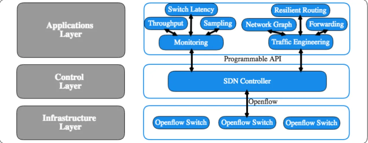
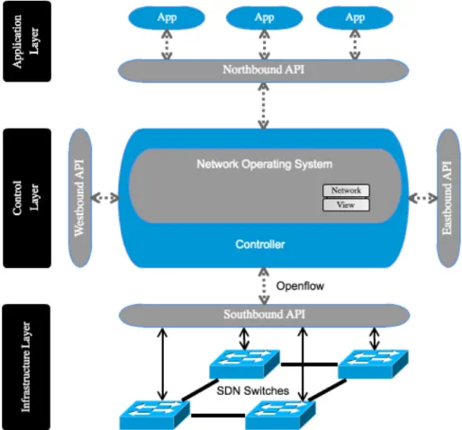
A SDN can be decomposed in the Network Operating System (NOS) and a set of net-work applications that define the policies to be implemented by the SDN switches(see Figure 2.1). The NOS offers services to the network applications and abstracts all the low level communication required to control the traffic forwarding on the SDN switches. This separation releases the network application programmers of the low level details of the interface specification, and abstracts future changes to the specification.
2.1.1 Architecture
The SDN architecture, as defined by the Open Network Foundation (ONF) [4], is a three-layer stack, composed of the infrastructure three-layer, the control three-layer and the application layer. The aim of this layered structure is to provide well defined interfaces that enable the development of software to control the connectivity provided by a set of network resources, and the packet traffic that flows through them. The remaining of this section details each component of the common SDN structure as seen in Figure 2.1.
The infrastructure layer, as in traditional networks, is responsible for forwarding pack-ets. These packets are transmitted according to the rules sent by the controller through a
Chapter 2. Related Work 9 communication channel that the device established with the controller. This communica-tion channel can be either out-of-band or in-band, depending on whether it is established through a dedicated interface or not. The network devices in this layer communicate with the controller using the Southbound API (typically, Openflow [3]). The control layer is the controller. This entity is responsible for maintaining a global view of the network and updating it according to the events received from the infrastructure layer. This Network View is then made available to the applications using the Northbound API (typically a REST interface).
The controller is also responsible for making any changes requested by the Applications Layer effective in the devices on the infrastructure layer. The Eastbound and Westbound API only exist when distributed control is employed (which is the common way in pro-duction). Finally, the Applications Layer is where the network logic resides. Here, appli-cations use the network view provided by the controller to enforce the global objectives required by the network administrators. Examples of such applications include firewalls, routing, traffic engineering, among others.
2.1.2 Openflow
Openflow is the most commonly used communications open standard between the control and the infrastructure layers. It defines a set of instructions that enable direct access to the network devices, allowing full control on how data packets are forwarded. These instructions are sent through a secure channel and are processed and stored on a table in the Openflow enabled switch (see Figure 2.2).
Openflow uses the concept of flow to identify traffic based on pre-defined rules, which are composed of match fields and actions, as defined in the Openflow specification [3]. When an Openflow enabled switch needs to know the appropriate action to take with a packet, it starts by parsing the packets and then searches its flow tables for a matching flow entry. When a match is found, the action defined in that flow entry is executed on the packet. Multiple actions can be applied to the packet such as adding, removing or changing specific header fields, drop the packet, forward the packet to a specific switch port, send the packet to the controller for further analysis, etc. The expected behaviour of a switch and the dataplane protocols supporting it, are also defined by this specification.
2.1.3 SDN Controller
A SDN Controller logically centralizes the network intelligence. The SDN controller runs in commodity server technology and can be placed anywhere on the network. It is responsible for managing the flow entries on the switches and take the appropriate actions to guarantee the correct flow of traffic. To accomplish this, it runs multiple applications that listen to switch events, such as link up/down. These events are sent by the switches
Figure 2.2: Openflow Switch [2] to the controller using Openflow messages.
As mentioned, the SDN controller is subdivided in two parts, the NOS and a set of net-work applications. The NOS uses its southbound interface to perform all the low level communication with the SDN switches, and employs it northbound API to provide ser-vices to the network applications. The Northbound API provides ways for network ap-plications to obtain information from the switches and also to define policies that will be used by the switches to process packets. The abstraction provided by the controller allows a faster development of network control applications. This makes SDN an ideal solution to create custom network behaviours that follow the applications requirements.
Bellow we present a few examples of SDN controllers.
NOX
NOX [5] was the first Openflow controller (2008). It was developed in both C++ and Python and has an event-driven programming model. It included in its core a group of applications that enable the creation of a single network view based on its observations of the network.
Chapter 2. Related Work 11 Opendaylight
Opendaylight [6] is an open source project supported by several major network companies like IBM, Cisco, Juniper and VMWare. It presents a new SDN controller layered struc-ture implemented in Java which aims to provide a ’universal’ SDN platform. Its Service Abstraction Layer allows the management of devices, using multiple APIs and protocols such as Openflow, OVSDB, NETCONF, SNMP, among others.
ONOS
ONOS [7] is also an open source project hosted by The Linux Foundation that was specif-ically designed to meet the needs of large operators while offering the flexibility to create and deploy new dynamic network services with simplified programmatic interfaces. Floodlight
Floodlight is an open source Apache licensed controller developed in Java that has been designed to have high-performance. The overall functionality comes from its modules, which use its core to communicate with switches. The implementation is multi-threaded and event based. In this work, we choose Floodlight for the following reasons:
• It offers a modular loading system making it simple to extend and enhance;
• Can handle mixed Openflow and non-Openflow networks making it ideal for an incremental update of the network to Openflow switches;
• It uses the asynchronous event based multithreaded library Netty, which improves performance on large networks, making it ideal for time critical applications; • It has a very active community of developers.
2.2 Network Routing
In general, routing aims to answer the question: ”What is the best way to get from point A to point B”. Network routing answers that question for every packet that enters the network, but dynamically since links go up and down, routers fail, and so the best route from A to B is constantly changing. When such actions take place, the existing routes have to be updated.
In traditional networks the control plane is distributed among all devices. This lack of a centralized view means that a routing protocol must be executed in the control plane of every device, so that each can update their own view of the network and know how to forward packets. Routing protocols can be organized in one of two classes. Some rout-ing protocols, such as Open Shortest Path First (OSPF) [14], and Intermediate System to
Intermediate System (IS-IS) [12] are link-state routing protocols [42]. Routing protocols in this class, map the connectivity of all the network in the form of a graph in each node. This requires any change in the network to be flooded to every node, whereas in a cen-tralized setting (as in SDN) only the controller is required to run the Dijkstra algorithm, on the new network topology. One advantage of this class of protocols is that they sup-port setting static weights to each link, such as cost, that are taken in consideration when choosing the best route.
The second class of routing protocols is distance-vector [42]. Protocols of this class only inform their neighbours about changes in the network. These protocols do not create a graph of the network, but instead they keep vectors with the distance in hops that a route takes to reach each node. These protocols use a distributed approach and have scalability issues. Example of such protocols are the Routing Information Protocol (RIP) and the Border Gateway Protocol (BGP).
2.3 Traffic Engineering
Communication networks are dynamic environments that require constant adjustments to improve user performance and making more efficient use of resources. Traditional routing protocols enable connectivity but they make it difficult to manage rapid changes in the network. This is the goal of Traffic Engineering (TE) [15, 19, 18]. The typical goal is to distribute load across the network to avoid hotspots. There are multiple ways to achieve this kind of optimization. One commonly used is Equal-Cost Multi-Path routing (ECMP) [16], where traffic is split among the multiple routes that have the same cost from point A to point B (multiple shortest paths). This technique can be used for instance in OSPF networks, producing better results than using OSPF alone (restricted to a shortest path).
2.3.1 Traditional Networks TE
Today’s networks typically use Multiprotocol Label Switching (MPLS) for TE. MPLS is an advanced routing scheme that provides extensions with respect to forwarding and path controlling. Each MPLS packet has a special label that the router uses for a lookup in its forwarding table. This enables routing not only based on the destination IP, but also on this label [20], allowing traffic to be sent through different paths even for the same destination addresses. By using MPLS with Constraint-Based Routing (CBR) [38] and reserving resources with the Resource Reservation Protocol (RSVP) [19], it is possible to increase substantially the efficiency of current networks.
Chapter 2. Related Work 13
2.3.2 Software Defined Networks TE
Despite the improvement that MPLS-TE brought to traditional networks, it is still far from ideal. Even with the most recent technologies and techniques, network providers are unable to fully leverage their investments, with the busier links still having an average utilization around 40-60% [39]. One of the main reasons that contribute to this low utiliza-tion is the poor efficiency of the distributed resource allocautiliza-tion that is used in MPLS-TE, as no entity has a global view, and ingress routers greedily select paths for their traffic. This leads to configurations where efficiency is suboptimal.
SDN offers a solution to this problem. The controller has a complete knowledge of the network and therefore it is capable of taking decisions that are globally optimal. This centralized control also eases the required frequent updates to the network data plane, necessary to maintain high utilization, since the execution of the complex distributed pro-tocols used in traditional networks is no longer necessary. SDN enabled providers to use their links for long periods of time at near 100% utilization [40] and improve the network global efficiency.
2.4 Network Monitoring
Network monitoring is the process of continuously measuring a computer network for multiple metrics, such as availability, delay, jitter, bandwidth, error rate, and loss rate. These metrics are fundamental to TE as it is based on these values that routing decisions are made. Network monitoring therefore is fundamental in allowing network traffic to be managed efficiently. Besides traffic engineering [39], network monitoring has multiple other applications such as anomaly detection [43], costumer accounting [32], Service Level Agreements (SLA) checking, identification of applications [29], forensic analysis [50], among others.
Network monitoring has such an important role in communication networks that multiple efforts from the research community have been made in order to provide solutions that are fine-grained, scalable and accurate. In the rest of this section we describe some protocols and technics used in monitoring systems.
2.4.1 Simple Network Management Protocol
The Simple Network Management Protocol (SNMP) [13] is an Internet-standard protocol created in 1988, still widely used to collect information about managed devices. Devices that support SNMP keep track of multiple parameters such as the amount of forwarded traffic, including the number and rate of packets (and bytes) forwarded, the packet er-ror rate, etc. The devices then expose their management data in the form of variables to which the Network Management Station (NMS) can access through GET requests. The
NMS periodically queries the network devices to obtain the desired monitoring infor-mation about the network. Accurate monitoring inforinfor-mation demands frequent queries to multiple parameters, which may degrade the network device efficiency due to CPU overhead. The information available in each network device is defined in a Management Information Base (MIB), which is vendor/model dependent. However, vendors tend to implement SNMP counters only for aggregate traffic, making SNMP not suitable for the fine-grained statistics required by traffic engineering. Earlier versions of this protocol allowed an attacker easy access to all the information provided by a device, but in later versions, starting in the version three, authentication, authorization, access control, and privacy, was added, limiting the attackers actions. Nevertheless, an attacker that is able to inject or drop traffic on a given link is able to remain unnoticed if one uses only this protocol to monitor the network.
2.4.2 Active Probing
Another approach to network monitoring is active probing. In this approach, a special packet is sent through the network, enabling information about the network status to be extracted, either by the receiver or by the sender. Tools such as ping, traceroute, tracert, and others implement some form of active probing. As such they can be useful to collect different sorts of information for many of the applications referred before, specially to monitor delay, loss rate, jitter, and available bandwidth. However, security concerns arise because an active attacker may be able to easily identify the probe packets and treat them differently from the normal traffic, to evade the monitoring system. For example, after having identified the packets that are used for latency measurement in systems such as OpenNetMon [25] and SLAM [51], an active attacker can delay the delivery of the probes to fool the link latency estimates calculated by the monitoring system. A smart attacker would then be able to control traffic routing, for example to direct packets to locations under his control.
2.4.3 Packet Sampling
The first packet monitoring solutions were based on specially designed equipment in-stalled on the network [26]. These machines would do passive monitoring by copying the entire contents of packets for further analysis. This approach relieved network de-vices from the monitoring overhead and enabled fine-grained monitoring, but it also put a lot of pressure in the monitoring machines and was very expensive to deploy. For scal-ability reasons, only the initial part of the packet [31], such as the protocol headers and the initial contents of the application data, were captured and stored. With the advent of high-speed switched networks this approach became infeasible, and packet sampling techniques started being employed [21] [22].
Chapter 2. Related Work 15 Packet sampling consists in randomly capturing only a subset of the packets (typically at a rate of 1:1000 or 1:10000), under the assumption that the subset is representative of the whole network traffic. This subset is then used to measure different properties of the traf-fic. Choosing a representative subset is specially challenging in communication networks given that even if a certain traffic exhibits a temporal cycle (daily, weekly), traffic engi-neering stations can blur that cycle by spliting or simply changing it from the ”normal” path. The sampling frequency is a specially important factor because it translates into the accuracy of the estimation procedure. With a low sampling frequency some network behavior might be missed, which can be harmful when performing anomaly detection. In the opposite side, high sampling frequency produces vast amounts of data that need to be processed, creating overhead in the devices, which can lead to packet loss. In any case, this technique is widely used, with protocols such as Netflow and sFlow.
Trajectory Sampling
One of the problems of the traditional sampling approaches is the lack of information on the exact paths packets follow. To solve this problem, in trajectory sampling the same set of packets is sampled, in both ingress and egress points. This allows the same packets to be tracked as they flow through the network. Existing implementations require special-ized hardware to be integrated in network devices. This technique enables also per-flow monitoring, which supports an even more fine-grained monitoring, and it has been used and studied in multiple works [46, 36].
2.4.4 SDN Monitoring
Flow-based measurements such as NetFlow and sFlow provide generic support for differ-ent measuremdiffer-ent tasks, but consume too much resources (e.g., CPU, memory, bandwidth) [33]. The centralized architecture of SDN and the per flow statistics supported by Open-flow are two major advantages when developing a monitoring system. The programability enabled by SDN enables a customised dynamic measurement data collection, making it possible to have the right amount of accuracy while minimizing resource consumption.
Approaches like OpenSketch [53] suggest the redesign of switches APIs to accommo-date for customized measurement functionality. With the proposed changes, their solution supports the collection of measurement data on a per flow basis and additional flow and data filtering. To accomplish this, switches execute a hashing function over the defined packet fields and count the number of packets that match a set of defined rules. This infor-mation is then stored within the switch in TCAM (Ternary Content-Addressable Memory) memories. Despite having advantages, such functionality would require an upgrade or re-placement of all network nodes. Others, such as OpenNetMon [25], focus solely on a few
metrics like delay, throughput and packet loss, not considering security or anomaly detec-tion. It makes use of Openflow functionality to periodically query the switches and obtain flow statistics to calculate the flow throughput and error rate, this makes it prone to traf-fic inflation/deflation attacks, since an attacker that controls a link on the monitored path can inject or drop packets making the throughput measurements incorrect. For latency measurement, OpenNetMon sends a probe on a specific vlan and measures the time the probe takes to arrive at the end switch of the monitored path. This allows a attacker that controls a link on that path to influence the latency measurement, since the attacker can easily identify the probe packet and delay it, tricking the monitoring system to measure a latency value different from the real one.
OpenSample [48] goes a bit further in regard to the granularity of monitoring information it analyses. By using sFlow, OpenSample is able to get more detailed information of the current network traffic, but does not focus on security, and is vulnerable to the attacks previously described. Similarly to OpenNetMon, SLAM also uses a recognizable probe to measure latency. Instead of measuring the latency of a path, SLAM measures the la-tency on a switch to switch basis, and accounts for the switch internal processing time. It focuses solely on measuring latency, not accounting for other important measurements such as error rate or throughput. It suffers from the same security issues as OpenNetMon. FlowSense [52] uses a passive technique to estimate network performance. In FlowSense, packet-in and flow-remove messages are used to estimate per flow link utilization. The communication overhead in this case is low, and it does not suffer from the security is-sues of active probing, but the estimation is not as accurate as with the active approaches. Despite the multiple works in this area, to the best of our knowledge none has considered the resilience aspect in network monitoring, which is our main goal.
2.5 Tools
We have used some tools to realistically emulate multiple topologies of a smart grid net-work and to evaluate our solution. These tools are described in this section.
2.5.1 Mininet
Mininet [8] is a software tool able to realistically emulate networks. It runs a collection of end-hosts, switches, routers and links on a single Linux kernel. Some advantages of using mininet are as follows:
• By using lightweight container-based virtualization they are able to make a single system to emulate a large-scale network with hundreds of nodes, with each device behaving like the real hardware;
Chapter 2. Related Work 17 • It allows the creation of custom topologies, from a single switch to Internet-like
topologies and also the execution of regular software inside each container;
• Packet forwarding is customisable because mininet switches can use the Openflow protocol.
Despite being fast and flexible, it also has some limitations:
• Since it uses lightweight virtualization, the Linux kernel is shared by all virtual hosts. This means that it is not possible to run software from other operating sys-tems;
• All virtualized systems execute on the same host, so it is necessary to limit traf-fic rates, otherwise performance issues may arise with the system becoming the bottleneck, not the emulated network under analysis.
2.5.2 Scapy
Scapy [9] is a powerful packet manipulation framework that is able to change packets in real time. It supports a wide number of protocols and is able to capture, decode, match requests and replies and send them on the wire. It also offers the possibility of creating packets from scratch and injecting them on the network.
2.5.3 Iperf
Iperf [10] is a tool for active measurements of throughput of IP networks. It implements a client and a server, and supports various protocols such as UDP and TCP. It can measure packet loss, delay jitter, and bandwidth/throughput.
In the next chapter we describe our solution which was designed to fill the gaps pre-viously identified while maintaining the requirements of Smart Grid networks. We will describe how our solution coupes traffic inflation/deflation attacks and also how we are able to perform trajectory sampling without the need of adding additional hardware for existing SDN switches.
Chapter 3
Design and Implementation
Our goal is the design and implementation of a SDN based solution to resiliently route smart-grid traffic at the WAN level. The solution consists of two applications. The first is a monitoring solution responsible for querying network switches to gather information about the current state of the network. The second application uses that information to create resilient routes along the WAN network. The solution aims to prevent several types of attacks, so we start this chapter by defining them.
3.1 Attack taxonomy
Given that traffic engineering decisions are based on information provided by the moni-toring system, an adversary might target the monitor to compromise routing decisions. In order to design a resilient solution, we have identified multiple attack vectors that might be exploited.
3.1.1 Generic adversary capabilities
Any device from the smart-grid network can be used as an attack vector. Even components that are not under our control pose a threat. In this section, we describe the capabilities of an adversary that aims to mislead our system.
Traffic eavesdropping: is the capability of an adversary to observe and record packets that pass through a link. One example of such attack is when an adversary has physical access to the wire that is used to connect two devices and is able to passively wiretap it.
Traffic injection: is the capability of an adversary to insert unaccounted packets into a link. One example of such attack is when an adversary has control of a device that is inside the network, which is employed to generate and inject packets.
Traffic interception: is the capability of an adversary to control the packet flow that traverses some resource, allowing him to manipulate any packet. One example of this kind of attack is when the adversary controls a device in the path between two SDN switches
(e.g., the forwarding devices used in a dedicated link provided by a communications op-erator) and uses that device to manipulate any packet that traverses it.
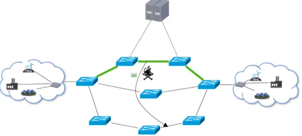
Traffic rerouting: is the capability of an adversary that controls two or more links to drop a given number of packets that are traversing a link and injects those same packets on any other link controlled by the adversary. One example of such attack is when the adversary controls two or more devices forming the path between two SDN switches under our control, and uses those two points to redirect packets. This particular attack is depicted in Figure 3.1, where the attacker drops packets flowing through the top path and injects them in another link under his control, on the bottom path.
Figure 3.1: Example of a packet reroute performed by the adversary
3.1.2 Attacks on latency estimation
Latency is one of the fundamental parameters used in traffic engineering. Hence, protect-ing its estimation is of crucial importance. If not properly protected, it can become the target of various kinds of attacks, performed by adversaries with access to the link being monitored.
The common SDN monitoring applications measure the latency of a link by recording the time a given packet leaves a link entry-point and when that same packet arrives at the link exit-point. The latency of the link is then calculated by subtracting the entry-point time from the exit-point time. The packet used for the estimation can be a special packet generated by the controller (a “probe” packet), or it can be a normal packet that is flowing through the link. We refer to this mechanism as probing, in both scenarios.
Below, we describe two adversary capabilities that are specific to the probing environ-ment:
Probe spoofing: the capability of an adversary to make a monitoring SDN application accept forged probes for estimating link delay values
Probe anticipation: the capability of an adversary to predict the timing of probe recep-tion by a monitoring SDN applicarecep-tion.
Chapter 3. Design and Implementation 21 Probe spoofing capability
An adversary can only successfully spoof probes if the monitoring SDN application can-not distinguish between a fake probe and a genuine. This capability presumes the adver-sary already knows about the probe generation and filtering mechanisms, e.g., by having access to the source code or by deducing the mechanism behaviour from repeated obser-vation of transmitted probes.
If the probes are invariable and the adversary knows about their content, spoofing probe packets is trivial. If the probes are variable but the SDN application does not check the validity of their contents (or does so incorrectly), then the adversary can spoof probes by forging packets with arbitrary contents. Specifically, the adversary may be able to in-sert contents in such a way that it effectively manipulates the SDN application into making erroneous delay calculations (e.g., if the contents include a timestamp that is used for cal-culating latencies, and the adversary inserts a fake timestamp). Importantly, wrong latency estimations can result in undesirable changes to packet routing (e.g., sending packets to locations controlled by the attacker).
If the probes are variable and the SDN application strictly checks the validity of their contents, i.e., if the contents of each probe received are validated by matching an exact byte sequence, then the adversary can still spoof probes if he can predict the contents of future legitimate probes (e.g., if each probe includes a sequence number that is incre-mented in every transmission, an adversary with eavesdropping capabilities can easily predict the next sequence number).
A different situation occurs when actual user generated traffic is used as probe. In this case, the SDN application mirrors to the controller part of the normal traffic to be used as probes, as they traverse the switches that interconnect the link being probed. In this case it becomes harder to spoof probes because their content is generated by the user application. However, if the adversary can first discover which data packets are being probed and reverse engineer the user application, he may be able to guess the contents of future packets, and therefore spoof probes, in case the application has predictable behaviour for at least a subset of the network traffic. As an alternative, the adversary could attempt to introduce packets in the network to be transmitted through the link.
Probe anticipation capability
An adversary with this capability can successfully predict the timing of probe reception by a monitoring SDN application (with a small error margin). If the attacker is able to guess the probe transmission frequency and the propagation delay between the adversary’s point of injection and the controller, he will be able to anticipate probes.
The probe transmission frequency may be static and known by the adversary if he or she obtains it via source code disclosure or deduced from repeated eavesdropping of transmitted probes. The transmission frequency may also be dynamic and dependent on
certain properties of the data traffic passing through the link (e.g., it may vary according to the current throughput). In this situation, the adversary may be able to deduce the frequency from continuously monitoring eavesdropped data traffic and by applying the same algorithm used by the SDN application. A similar strategy could be employed in the scenario where the probes are normal data packets that are mirrored to the controller. Attacks Forms
An adversary can attack the latency estimation using the previously described capabilities in the following ways:
Probe poisoning: An adversary with the capability of probe spoofing and probe antici-pation sends probes at specific (shorter than normal) times, making the monitoring system estimate lower link delay values. If the monitoring system uses the probe to transport a timestamp, it is also possible to force the monitoring system to estimate longer link delay values.
Probe flood: An adversary with the capability of probe spoofing continuously sends spoofed packets, leading the monitoring system to calculate incorrect delay esti-mations, as these packets arrive with high probability at unexpected times.
Probe replay: An adversary with traffic eavesdropping and traffic injection capabilities eavesdrops legitimate probes and injects them at a later time. Since the probes suffer higher delays the monitoring system will estimate larger link delay values. Probe disturbance: An adversary with traffic interception capability intercepts all
pack-ets and selectively delays either the data traffic or the probes, making the calculated link latency values inconsistent with the real propagation time of data packets.
3.1.3 Attacks on throughput estimation
Another fundamental parameter in traffic engineering solutions is throughput. To obtain this estimate, a monitoring SDN application can leverage the capability of SDN devices to report traffic statistics to the controller in order to estimate traffic throughput at any given moment in a link. For example, Openflow-enabled switches can report periodically the total number of bytes transmitted/received in some port. As that same report can include the elapsed time since the previous request, two consecutive reports from the same switch enables the SDN application to calculate the average (transmission/reception) throughput of the switch port. This mechanism is also prone to attacks.
Throughput inflation: An adversary with traffic injection capability can add traffic on a link under his control, increasing the real throughput on that link. As a result, the
Chapter 3. Design and Implementation 23 monitoring application would be presented with a lower entry throughput (to the link), when compared to the exit throughput.
Throughput deflation: An adversary with traffic interception capabilities can drop pack-ets that flow on a link under his control. In this case, the monitoring application would be presented with a higher entry throughput, when compared to the exit throughput.
In either case, depending on how the monitoring application acts, inflation and defla-tion attacks could negatively influence the decisions made by other modules, including those of a traffic engineering application.
3.2 Threat model
We consider that the link between two SDN switches under our control can be composed of an arbitrary number of other components, such as routers and switches, which may or may not be SDN-capable. An adversary may want to attack the monitoring system of the network to influence routing decisions, by using any of the previously described capabilities. We limit the adversary actions to the WAN data plane. Attacks in the NAN and the HAN, and in the switch-controller connections are out of scope. With respect to the latter, we assume that the communication channel used between the SDN switches and the controller is secure (e.g., using TLS, as per the Openflow specification), and that the SDN switches themselves are not compromised by the attacker, meaning that they operate accordingly to their specification.
3.3 Monitoring
The monitoring module consists of various submodules, as represented in Figure 3.2, that gather information about the current state of the network. Multiple techniques are used in order to effectively obtain the most up-to-date information about the network, while ensuring correctness of that same information, and while minimising the performance impact. The monitoring module periodically queries all switches to extract information on its counters and port status so that it can build the global network state. As it is possible to control the monitoring period, this method has low overhead. However, this technique has vulnerabilities that make it prone to several attacks to monitoring [35]. For protection, we have devised an algorithm that verifies if there are ongoing attacks to mislead the monitoring which resorts to random trajectory sampling at its core.
Trajectory sampling is a method of packet sampling where packets that flow through a given link (or subset of links) are sampled within a measurement domain. The main difference from normal packet sampling is that in trajectory sampling one also “follows”
Figure 3.2: Monitoring architecture
the packets along the paths. For this to be possible, it is not enough to just randomly sample each link, as one would not be able to derive the precise path that a sampled packet has followed through the measurement domain, from the ingress point to the egress point. For this purpose, a deterministic hash function is executed for each packet that traverses the network device. This allows tracking a packet as it flows throughout the network, and usually requires specialized hardware to be integrated in network devices. This technique enables fine-grained, per-flow monitoring, and as such has been used in multiple works [46, 36]. With this technique we are able to verify if the values that we receive from different switch counters are correct, denying the attacker a way to mislead the system.
In the following sections we give details on the design of the monitoring submodules, with a focus on how they ensure the correctness of the monitoring information.
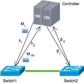
3.3.1 Control plane latency
In order to detect attacks and have a higher degree of confidence in the information ob-tained from the switches, our solution always probes the two switches that are the end-points of the link that is currently under evaluation. As mentioned before, SDN has the control plane separate from the data plane, which means that when the controller commu-nicates with the switches there will be a delay between the issuing of the message and its delivery. In other words, when the controller sends the message to add a new entry to a flow table, this message will take some time to arrive at the target switch and to be actually applied. Even though this amount of time is normally very small in local networks, this may not be true in Smart Grids given the diversity of communication technologies that may be employed. So it becomes important to accurately estimate the delays that control messages experience.
data-Chapter 3. Design and Implementation 25 plane device. This information is then made available to the other monitoring submodules so that they can correctly perform their time calculations. This will make monitoring more accurate and will cause less performance impact on both dataplane and control plane.
3.3.2 Throughput
The Openflow specification [3] defines a set of messages that the controller can use to obtain data from the network devices. We use this functionality to periodically collect the total number of bytes transmitted/received by some port. As explained, by subtracting the values from two consecutive reads and dividing by the number of seconds of the moni-toring period, one can calculate an estimate of the throughput for that given device port. In order to detect possible deviations due to congestion on the device-to-controller-link or (possible) attacks to the estimation, the measurement is made on both ports of the link and then compared. If the measurements are too far apart then a second measurement is made to increase the probability of detecting throughput inflation or deflation attacks, or simply to confirm that the difference was due to a normal increase in the jitter induced by the network.
This technique causes the least overhead on the dataplane devices because we are only querying the switch registers, but is vulnerable to attacks. Our solution copes with this problem using the sampling technique described next.
3.3.3 Sampling
As mentioned before, several attacks might corrupt monitoring measurements if they af-fect a specific set of switches. To address this problem we resort to a novel variant of tra-jectory sampling. The main advantage of our solution is that it does not require complex hardware in the switch for its materialization. Our solution requires only conventional Openflow switches.
The goal is to compare the same set of packets that pass through the source switch of a given link, with the ones that arrive at the destination switch, during a specific period of time. As such, it allows us to verify if packets were modified, injected or dropped. This supports the detection of an ongoing attack on that link under the following conditions:
1. If the number of sampled packets on the destination switch is greater than the pack-ets on the source switch, then packpack-ets were injected;
2. If the number of sampled packets on the destination switch is less than the packets on the source switch, then packets were dropped;
3. If there is not an exact match on the content of every packet sampled at the source switch when compared to the same packets sampled on the destination switch, then
packets were modified;
Detection can only be effective if the attacker cannot predict which packets are being sampled. Therefore, our solution samples random links during random periods of time at random intervals. Given the sampling randomness, an attacker cannot determine when a sampling is being performed on any given link, and therefore he/she cannot mislead our monitoring system, allowing any attack to be eventually detected. To perform trajectory sampling in an SDN, the packets being sampled need to be duplicated during the sam-pling period at the source and destination switch of a link, and sent to the controller for further processing. This can degrade the performance of the dataplane, so it is important that the algorithm responsible for performing trajectory sampling is dynamic and adapts to the current network and switch performance conditions. The sampling submodule will set the sampling time accordingly to the current throughput of the link, so that the amount of packets sampled does not negatively impact performance. As such, if a link is experi-encing high throughput, then the sampling frequency is reduced.
3.3.4 Loss Rate
The loss rate is the number of packets that enter a link but do not arrive at the desti-nation, divided by the total number of packets that entered the link in that period. This information can be directly obtained from the previously described sampling algorithm by comparing the packets that arrived at the destination switch versus the ones that traversed the source switch. Since the packets that traverse the source switch are compared with the same packets that arrive at the destination switch, any packet that was changed by the attacker is considered as loss. Thus, the loss rate takes into account both the packets that were dropped due to accidental network failures, and the packets that are dropped or tampered by an attacker.
3.3.5 Monitoring API
All the information that is gathered by the monitoring submodules are made available to all other SDN applications through the monitoring Application Programming Interface (API). SDN applications interested in obtaining information about any link can either obtain it as notifications or on demand. The routing and traffic engineering module we describe next is an example of an application that uses this API to react to network changes and push novel forwarding rules to the SDN switches. By opting for this modular design, we allow other SDN applications to use this module as its secure monitoring base.
Chapter 3. Design and Implementation 27
3.4 Traffic Engineering
The traffic engineering module and its submodules are shown in Figure 3.3. This module uses the information provided by the monitoring module to continuously evaluate if the smart-grid requirements are being met. In the following sections we describe the role of each submodule and how they enable resilient routing.
Figure 3.3: Trafic engineering module architecture.
3.4.1 Smart Grid Requirements
Different smart grid applications have different requirements when it comes to bandwidth, loss rate and latency. The smart grid requirements submodule is responsible for storing such information and also for verifying if a given route with specific bandwidth, loss rate and latency characteristics comply with the specific needs. This information is used by the Resilient Routing submodule to decide if a given route can or cannot be used for a specific smart grid application.
3.4.2 Network Graph
One of the advantages of SDN is the centralization of the network global view in the con-troller. This eases the process of updating a route in case if certain network events such as link failures, as it avoids the need for complex distributed algorithms to be executed. The Network Graph submodule is responsible for building that global network view in the form of a graph. This graph is constantly updated with the current network topol-ogy, allowing operations such as obtaining the shortest path between two points of the network by simply running the Dijkstra algorithm. Not having to resort to complex and time consuming distributed algorithms to re-route traffic around failed links is especially important in this context, as several smart grid applications are sensitive to latency and
packet loss.
By maintaining this up-to-date global view of the network our solution is able to quickly react to changes in the network topology causing less impact on latency and packet loss.
3.4.3 Resilient Routing
The Resilient Routing submodule is the core of the traffic engineering module. This submodule is responsible for combining the information provided by the network graph submodule, smart grid requirements submodule, and the monitoring module to make rout-ing decisions. It continuously checks the information provided by the monitorrout-ing module and cross-references it with the needs of the smart grid requirements submodule in order to confirm that every smart grid application is running within its pre-defined limits. If a given requirement is not being met or if a link goes down on a specific route, it uses the information of the Network Graph submodule to quickly calculate the best new route between the affected points, taking in consideration the number of hops and link statistics. Our solution considers as best route the shortest path (the path with the least number of hops) that is compliant with the smart grid application requirements.
The existing separation between the control plane and the data plane in SDN is ben-eficial in multiple ways, but has a few drawbacks. For very time sensitive smart grid applications, the time it takes for a switch to send the information to the controller that a link has gone down, added to the time the controller takes to process that information and propagate the new route to the dataplane devices, may be incompatible with the require-ments of specific smart grid applications. To cope with this issue, our solution is designed so that in the case of such event the data-plane devices already have the information on where to re-route the traffic. This is accomplished by means of backup routes. This route is installed in switches but is only used when the dataplane device detects that the normal route for a given packet is no longer valid, such as when the egress port is down due to link failure.
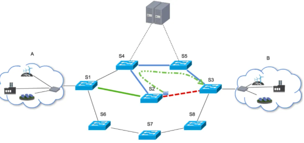
Taking as example the network depicted in Figure 3.4, while calculating the route between A and B, the resilient routing module has chosen the route composed by A-S1-S2-S3-B. This selection was made because at the time this was the shortest path that was compliant with the smart grid applications requirements. Besides the normal route, the controller also calculates backup routes and installs them on each dataplane device so that if a link (or switch) goes down on the normal route, the dataplane device that detects that failure will quickly divert all packets to the backup route.
Chapter 3. Design and Implementation 29
Figure 3.4: Backup route in action
As an example lets assume that the doted line between S2 and S3 represents a link failure detected by S2. In this case accordingly to the backup route, S2 will send the packets to S4, which will detect that these packets are using the backup route. Therefore, it will forward the packets to S6 and then to S3 before final delivery to B, as denoted by the chained line.
More complex cases are also covered, as when the backup route requires the packets to return back a few links before being transmitted through an alternative path (as is visible in 3.5).
Figure 3.5: Complex backup route in action
In this example, the link between S5 and S3 has failed and since S5 had no lateral path to forward the packets that lead to B, packets will return back to S1 and then will follow the backup route composed by S1-S6-S7-S8-S3-B. Therefore, a packet that was sent from A would take the path A-S1-S4-S5-S4-S1-S6-S7-S8-S3-B as denoted by the chained line. This will guarantee that if there is an alternative path, no packet will be lost (starting from the moment the dataplane device S5 detects that its link to S3 is no longer up). After the controller is notified that the link is failed, it will recalculate the routes and
![Figure 1.2: Smart Grid Information Flow [1]](https://thumb-eu.123doks.com/thumbv2/123dok_br/15482879.1038647/19.892.128.767.107.330/figure-smart-grid-information-flow.webp)
![Figure 2.2: Openflow Switch [2]](https://thumb-eu.123doks.com/thumbv2/123dok_br/15482879.1038647/26.892.184.701.100.551/figure-openflow-switch.webp)