Concept Generation and Integration of a Lifting Mechanism on
a Campus Bus
Design Studio/INEGI
Ioana Adina Neacşu
Diploma Project
Orientador na FEUP: Prof. Fernando Gomes de Almeida
Faculdade de Engenharia da Universidade do Porto Mestrado Integrado em Engenharia Mecânica
Summary
The project’s aim is to create a mechanism that will facilitate the transportation of people with disabilities (students and teachers) in a campus bus. This will encourage the integration of disabled people in the community and will also consist a technical
challenge for the designers.
Practically the project has two main parts: researching the field to find all the necessary information and data related to such a mechanism, and the second part being the actual design of the mechanism.
For the first part we talked to specialists, personnel responsible with the rehabilitation of people with disabilities and manufacturers of equipment needed for our project. We analyzed the strengths and weaknesses, the parts we should insist on, creating a
hierarchy of the most important issues that are primary for the project. This analysis was made from two points of view, from the passenger’s point of view and from potential customer’s point of view, that may be interested in buying our product. The second part implies strength and dynamic calculations, 3D simulations, design and selection of proper technologies that would be used for the mechanism.
The results obtained are summarized in the last chapter, consisting of conclusions of the work that has been made.
Acknowledgment
We would like to express our thanks to a series of professors from both the host and home universities that offered us their support throughout the our work on this project: - coordinators: prof. Fernando Gomes de Almeida, University of Porto and prof. Stefan Pastrama, Department of Mechanical Engineering, University POLITEHNICA of Bucharest.
- professors: Jorge Lino, Carlos Aguiar and Xavier Carvalho from Departamento de Engenharia Mecânica e Gestão Industrial, FEUP and prof. Tiberiu Laurian, Department of Mechanical Engineering, University POLITEHNICA of Bucharest.
We offer our thanks also to:
- Mrs. Cristina Crisóstomo from Centro de Reabilitação Profissional de Gaia (CRPG) - Mr. Antonio Bernardes, from the ABER Company.
We are grateful as well to Carla Monteiro, Assistant to EDAM and Transportation Systems MIT PT, and to our colleague Ricardo Almeida, IT & PM consultant, MIT Portugal, PhD student from the Design Studio in FEUP where we performed most of our work on the project.
Index of Contents
1 Abstract ... 9
2 Purpose of the project. Requirements and objectives ... 10
3 Concept development ... 11
4 Dynamic computations ... 35
5 Briefing on Strength analysis ... 58
6 Actuation technology ... 61
7 3D Drafting of the mechanism... ... 71
8 Conclusions. ... 83
Detailed Content and Student’s Individual Contribution to the Project
1. Abstract ………..Ioana Adina Neacşu 2. Purpose of the project. Requirements and objectives …………....Ioana Adina Neacşu 3. Concept Development ………...Ioana Adina Neacşu 3.1 Preliminary Product Research
3.1.1 Identifying customer needs 3.1.2 Gather Raw Data from Customers 3.1.3 Organize the Needs into a Hierarchy
3.1.4 Interpret Raw Data in Terms of Customers Needs 3.1.5 Establish the Relative Importance
3.1.6 Reflect on the Results and the Process
3.2 Product Specifications……….……….…..Ioana Adina Neacşu 3.2.1Establish Target Specifications
3.3 Concept generation………...…………...Andreea Ştefan 3.3.1 Clarify the Problem
3.3.2 Search Externally 3.3.3 Search Internally 3.3.4 Explore systematically
3.3.5 Reflect on the Results and the Process
3.4 Concept Selection………...………Andreea Ştefan 3.4.1 Refine concepts
3.4.2 Expose final designs (Design no. 1, 2 and 3 ).
3.5 Final Concept ………...Andreea Ştefan 3.5.1 Analyzing the mechanism - Design no. 3
3.5.2 Design Details of each of the mechanisms of the final concept 3.5.2a The Scissors linkage
3.5.2b The Translation mechanism 3.5.2c The Ramps-movement mechanism
4 Dynamic Computations………...Ioana Adina Neacşu 4.1 Pre-dimensioning
4.2 Introduction to ADAMS 4.3 Creating the model 4.4 Testing the model 4.5 Reviewing the model 4.5.1 Static analysis 4.5.2 Dynamic simulation
5.Briefing on Strength Analysis ………..………..Andreea Ştefan 6 Actuation Technology
6.1 Selection and design of the hydraulic equipment…………..…Ioana Adina Neacşu 6.1.1 Principal Actuation System
6.1.2 Secondary Actuation System
6.2 Electric Control of the mechanism………Ioana Adina Neacşu 6.3 Sliding mechanism……….……..Andreea Ştefan
6.4 Safety system……….………..Andreea Ştefan 6.5 Front ramp actuation………...……..Andreea Ştefan
6.6 Safety floor...Andreea Ştefan 7 3D Drafting of the mechanism and detailed operation...…………Ioana Adina Neacşu 8 Conclusions
9 Bibliography
Special note
Designing a lifting device mechanism for people with locomotive disabilities to be used on campus bus was considered a complex project, thus the work was assigned to a team of two. Together with my colleague Andreea Ştefan, I have completed the necessary investigations required by such a project. Her work is gathered in the thesis with the title “Design of a lifting device mechanism for people with locomotive disabilities to be used on campus bus”. I have included only a summary of her work in the present paper, and one can refer to her paper to verify in detail the interrelationship between our papers.
1 Abstract
The objective of this thesis is to design a lifting device that facilitates getting in/out of an existing bus of the people with locomotive disabilities.
The present work makes part of the CIVITAS project that is going on at the Faculty of Engineering – University of Porto, Portugal. The CIVITAS project involves the design of a campus bus out of an existing one, that the Faculty has in its possession. Our target is to develop the best solution for the lifting device, taking into account the physical and material constraints as well as the passenger’s safety and easy accessibility of the device.
Nowadays there exist a set of lifting devices that have been implemented on a limited number of public transport busses, on specialized or on personal vehicles. The device developed in this thesis reveals a relatively new concept that is fitting the space, safety and easy-access requirements of the project bus.
To achieve the goals of this project, we followed the product design methodology from specialized books that lead us to the final concept which was submitted to structural analyses and that will be furthermore optimized and animated using a computer aided design program.
Careful consideration of functional and physical domains guided us to an effective solution to this design problem. This solution is viable from the point of view of structural analysis and with continued work we hope that it may someday come to fruition as an effective and useful product.
2 Purpose of the project
The project consists in the development of the product until the stage of an analytical prototype and its modeling, the next stages being continued by the time the material resources are available.
The first aspects of the project were identified in order to be able to start the process of design. Among them there are:
a) Operating Environment. The device will be mounted on a bus that will circulate inside a student campus, with wide roads, 5 days per week.
b) The product has to be able to lift all types of wheelchairs(standard wheelchairs) and the maximum possible weight for these cases, which is 350kg.
c) The product has to adapt to the constraints of the bus design:
- space inside the bus - time of operation - safety
- stability
3 Concept development
Following the steps and indications featured in the publication “Product design and development” by Karl T. Urlich and Steven Eppinger [1], we have developed the concept and chose the most suitable one for our mechanism.
3.1.1 Identifying the customer needs
Like any other product, our attention as producers is focused on the customer needs. The concept of customer in our case can be split into two categories:
- the effective users of the lift, and
- different companies that wish to implement our mechanism on various buses.
The possible buyers of the mechanism shall be referred to as customers, while the term
users will be used for the real beneficiaries of the lift (people with locomotive
disabilities).
In this paragraph we will be discussing in parallel about both types of needs (customers and user needs).
3.1.2 Gather raw data from customers and users
According to the statistics performed by the Bureau of Transportations Statistics - U.S. Department of Transportation, when having to use a lift mechanism, users think about safety and the ability to use the lift first. Other factors include the size of the user, wheelchair size, and how else the van will be used- weather is a normal bus, or a private bus designed especially for disabled people.
From the point of view of customers buying the idea, other issues might be of a greater importance: total cost, maintenance cost and difficulty, easy to be adapted to more types of buses or how much does the mechanism respect the rules and regulations referring to lifts of people with disabilities.
Observing the product in use helps producers notice important details about customer/user needs. During a visit in a rehabilitation center in Gaia (Centro de Reabilitacao Proffisional de Gaia), we took notice of two main solutions for getting disabled persons into the bus:
- side ramp, fulfills its main function and is cheap- advantage to the customer, but needs an additional person that helps the person in the wheelchair to get on the bus- disadvantage for the user;
- folding platform that consists of a metal plate that goes outside the bus, and through an hydraulic actuation, it transports the wheelchair inside the bus. The main drawbacks are that the controller for this system is not available directly to the user (so again another person is needed to hold the controller), and that the security fixing inside the bus cannot be performed by the user himself.
3.1.3 Interpret raw data in terms of customer needs
From the point of view of users the following needs have been identified:
To lift the desired weight
Simple actuation Safety outside
Safety inside Easy access
Relatively short time of operation Back-up system
Stability
From the point of view of customers the following needs have been identified:
Low Cost Easy Adaptable
Long life
To lift the maximum weight
Suitable for a wide range (from standards) of wheelchairs Is lightweight
Short time of operation- when used Can be accessed for maintenance
Utility cost
Allows easy replacement of worn parts
Not to interfere the well functioning of the other parts of the bus Low noise level
Small overall dimensions
Adaptable to different levels of ground
Operational Environment
3.1.4 Organize the needs into a hierarchy
The goal of this step is to organize the above needs into a hierarchical list so that the result is avoiding work with a large number of detailed needs which are difficult to summarize for use in subsequent development activities.
The list will consist of a set of primary needs, each one of which will be further characterized by a set of secondary needs. The triple-star symbol signifies the highest importance.
***To lift the desired weight ***Safety outside
The mechanism is stable
The mechanism is perfectly horizontal The mechanism has anti-slip surface
The mechanism has a threshold warning signal The mechanism has handrails
The mechanism has edge guards ***Safety inside
The mechanism provides security belts inside the bus ***Long life
The mechanism survives heavy use The mechanism can be easily maintained The parts can be easily changed
**Simple actuation
The mechanism can be actuated by simple button pushes. **The mechanism is stable and vibration free
**Low Cost
The device should not exceed the average price of similar products on the market, but opposite, being economically reliable.
**Easy Adaptable
The mechanism is designed to work on more types of buses **Suitable for a wide range (from standards) of wheelchairs
The mechanism works with electric wheelchairs The mechanism works with manual wheelchairs *Is lightweight
**Short time of operation- when used
The mechanism performs the least number of movements **Utility cost
The mechanism consumes little energy and fuel. *Low noise level
The parts in motion permit lubrication to reduce noise The mechanism is phonic isolated
*Small overall dimensions
The mechanism fits easily in the structure of the bus The mechanism occupies little space inside the bus **Adaptable to different levels of ground
The mechanism detects the level of ground *Light for night operation
The mechanism has intermittent lights delimitating the operating space * Easy access
* Relatively short time of operation
* The mechanism has a manual back-up system
3.2. Product Specifications
3.2.1. Establishing target specifications
Customer needs are generally expressed in the ´language of the customer´ being helpful in developing a clear sense of the issues of interest to clients. Even so, they provide little specific guidance about how to design and engineer a product, therefore, at this level our aim (the development team) is to establish a set of specifications which spell out in precise, measurable detail what the product has to do. A specification consists of a metric and a value. For example, ´average time to get the wheelchair inside the bus´ is a metric, while ´less than 15 seconds´ is the value of a metric. Thus, in the early stage of development, the product specifications have been identified and only after this we can proceed to design the product that will meet those specifications.
For establishing the specifications of the product we followed the steps below:
a) Prepare the list of metrics
The most useful metrics are those that reflect as directly as possible the degree to which the product satisfies the customer needs. The importance of a metric is derived from the importance ratings of the needs it reflects.
THE NEEDS-METRICS MATRIX
metric associated with the cell are related. Performance relative to the metric will influence the degree to which the product satisfies the customer need.
b) Development of a cost model of the product
The purpose of this process is to make sure that the product can be produced at the target cost. The target cost refers to the manufacturing cost at which the company can make adequate profits while still offering the product to the end customer at a competitive price. It is also a kind of performance model, but instead of predicting the value of a technical performance model, it predicts cost performance.
In order to estimate the first manufacturing costs, a bill of materials is drafted, which contains a list of all parts and the estimation of the fabrication or purchasing price for each component. The bill of materials is useful throughout the development process and is updated regularly to reflect the current status of the estimated manufacturing cost. At this point of concept development, in the above mentioned list cannot yet be included all the components because of the complexity of the product itself. Table 3.1shows the major components and the subsystems with their corresponding cost boundaries.
Table 3.2 Bill of materials with cost estimates
Component Quantity High[€] Low[€] High total[€] Low total [€]
Platform structure Platform Aid-Handle bar Principal arm Secondary arm Middle bearing Side bearing
Hollow square profile Bushing Translation system Backup system Hydraulic Cylinder Hand pump Belt system Movable floor
Electric motor with gearbox Ramp
Bolts and screws
1 1 1 1 4 2 8 2 6 2 1 1 1 1 1 1 1 20 120 100 20 90 30 50 25 50 10 2000 50 750 400 50 50 110 15 5 75 90 10 75 15 40 15 35 8 1500 40 500 200 40 30 80 10 2 120 100 20 90 120 100 200 100 60 4000 50 750 400 50 50 110 15 100 75 90 10 75 60 80 120 70 48 3000 40 500 200 40 30 80 10 40 Total 6435 € 4568€
3.3 Concept Generation
The concept generation began with a set of customer needs and target specifications and it continued with a sequence of steps that imply the use of some classical tools in the concept development process. In the end it has resulted in a set of product concepts from which the final one was selected on the basis of a continuous refinement.
3.3.1. Clarify the Problem
After reflecting upon the general understanding of the purpose of the project we decomposed the overall problem into smaller problems as it follows:
Electrical Energy --»Convert Electrical Energy into Mechanical Energy --»Store Energy---»Apply Mechanical Energy to the Device
The starting point is sketching our product as a black box with main inputs and outputs, also known as Overall Functional Decomposition, as it can be seen bellow:
Overall Functional Decomposition
The main functions of the product are the inputs of the black box (see sketch above).
Figure 3.1 Applying Mechanical Energy to the weight Function
Refinement of the Functions
A more specific description of the problem is obtained by refining the functions into subfunctions. Each subfunction describes a specific operation or category of operations in order to sum up for the overall function of the product. This process is repeated until we establish that each subfunction can be analyzed separately without implying a specific technological working principle for the product concept.
For example, the Applying Mechanical Energy to the weight subfunction will be further split including subfunctions such as Taking the device out of the bus subfunction that will involve the sequence all actions that will lead to the fulfillment of that specific subfunction. Of course, it is here where the designer has the freedom to develop many ideas and limit the concepts to a reasonable number that will be analyzed further.
Once the problem decomposition has been completed, we have decided to focus on the analysis of the critical subfunctions. Each of the subfunctions will end by being
analyzed taking into account their importance.
The primary subfunction that consists the major interest of the project and that will be analyzed in the next paragraphs is the application of the mechanical energy to the lifting device, the set of movements that will ensure the entire operation of lifting and getting in/out of the bus (see Figure 3.1).
3.3.2 Search externally
During the concept generation stage external search helps to find existing solution to both the overall problem and to the subfunctions previously identified. There are more ways of gathering this kind information, among of them we have used: consulting experts, search patents and search published literature.
Consulting experts is an efficient way of gaining knowledge from experienced professionals that have encountered one or more of the subfunctions that the project is facing. Also, experts can redirect the search in a more specific area which usually returns useful information.
The experts we interacted with during our project work and the information we gathered from there are briefly described bellow:
1) CRPG (Centro de Reabilitacao Profissional de Gaia, near Porto city, Portugal) is a platform of specialized resources, to support people whose career was affected by illness or accident, rehabilitating or converting them professionally at the contexts of work, promoting their adaptation and adjustment, thus enabling the continuation or resumption of employment.
The purpose of our visit was to observe closely the functioning mechanism of a lifting platform for people with disabilities mounted on a special van, and thus to notice which are the drawbacks of such a system, what can be improved and which is the opinion of the end-user.
- the minimum available space provided inside the bus (and also on the lifting platform) should be 0.75x1.0 [m] - the precision stop until the level of the ground should be higher than +/-0.02 [m]
- if the level difference between the floor and the platform is greater 0.75 [m] protection
bars or doors at the access of the platform must be available
- all the edges of the platform (except the ones that allow access) must have protection
shields of at least 0.1 [m]
- the control of the platform must be visible.
2) ABER is a manufacturer of hydraulic equipments and specialized on elevation systems for both heavy industry and home applications. As featured products we can mention gear pumps, oil bent hydraulic motors, hydraulic tipping valves and various models of flow dividers. The discussion with one of their specialists lead us to consider hydraulic actuation as a feasible solution for our lifting problem. Hydraulics offer a good power/weight ratio, are highly reliable with minimum maintenance, can withstand over-loads without damage, are simple to control and have a high rigidity.
The visit to ABER also provided us an insight on the elevation systems, especially on the manufacturing and principle of functioning of the scissors linkage as well as on the hydraulic network, the overall dimensions a hydraulic equipment can have and the way you can purchase it.
Search patents
We have found on United States Patent website several manufacturers that represent a rich source of technical information, containing detailed drawings and explanations of how similar already existing products work. The information we found helped us in our concept development and will be stored in the Annexes part of the project.
Published Literature
Published literature includes journals, conference proceedings, trade magazines, government reports, market, consumer and product information. Thus we have conceived a list of sources of information of existing solutions, mainly using
engineering references such as Mark’s Standard Handbook of Mechanical Engineering and Mechanisms and Mechanical Devices Sourcebook. This part will be included as well to the project’s annexes.
3.3.3 Search internally
Following both individual and group working sessions regarding the subproblem of conversion of energy and set of movements needed for the entire operation of the device, we have made a table with possible solutions for each of the subfuntions involved(see Table 3.2).
Table 3.3 Possible Solutions for the implementation of the Actuation Subfunction Solutions to the subfunction of Taking the device out of the bus Solutions to the sufunction of Adjusting the device to the ground level Solutions to the subfunction of Lifting/Descending the device Solutions to the subfunction of Taking the device inside the bus Hydraulic equipment Proximity
Sensors Arm Actuation Linkages
Pneumatic
equipment Springs Cam Actuation
Pneumatic equipment Linkages Hydraulic Cylinder Rack Actuation Worm drive gearing
Ballscrews Pneumatic Cylinder Pneumatic cylinder Ballscrews Worm drive gearing Cam Rotary hydraylic cylinder Hydraulic equipment Leadscrew driver Leadscrew driver 3.3.4. Explore systematically
Using a systematic exploration we have analyzed the space of possibilities by
organizing and synthesize the solutions we concluded in previous paragraph(see Table
3.3).
There exists two specific tools that we have used in our work for managing the complexity of the problem and organizing the thinking, and these are the concept
Classification Tree and the Concept Combination Table.
The Concept Classification Tree is used to divide the entire space of possible solutions into several distinct classes which will facilitate comparison and pruning. We have used the classification tree to show the alternative solutions to the energy source subfunction.
Figure 3.2 Concept Combination Tree
The Concept Combination Table provides a way to consider combinations of solution fragments systematically. The columns in the table correspond to the subfunctions identified in an earlier stage. For example the subfunction of Applying Mechanical Energy to the Weight and its subfunctions are headed in the columns bellow. The entries in the column of the Taking the Device out of the Bus function are a hydraulic equipment, a lead screw driver, a solenoid or a worm drive gearing.
Partial solutions to the overall problem are formed by combining one fragment of each column. The combination of fragments are refined before an integrated solution emerges(Table 3.4).
Table 3.4 Concept Combination Table for the Actuation Function
3.4 Concept Selection
3.4.1 Refine Concepts
The technical analysis made previously indicated us some potentially viable designs that will be presented in this paragraph. The selection process usually indicates a
comparative analysis of the available design solutions. A decision matrix (Table 3.5) helps to identify the best solution by forcing one to consider a variety of factors in a systematic way.
The decision matrix.
The rows are dedicated to designs and the columns are assigned categories in which the designs are to be judged, such as cost, ease of use, efficiency, performance, reliability and any others that are appropriate to the problem.
Each category is then assigned a weight factor, which measures its relative importance.
Table 3.5. The decision matrix
Cost Safety Performance Reliability RANK
Weight Factor 0.25 0.35 0.15 0.25 1.0 Design 1 5 8 7 7 6.85 1.25 2.8 1.05 1.75 Design 2 4 7 6 5 5.6 1.00 2.45 0.90 1.25 Design 3 7 8 7 7 7.35 1.75 2.8 1.05 1.75
The body of the table(Table 3.4) is filled with numbers which rank each design on a convenient scale, such as 1 to 10, in part. We have examined the designs and have scored each of them.
The scores are then multiplied by the weight factors(which are usually chosen so as to sum up to a convenient number such as 1) and the products summed for each design. The weighted scores then give a ranking of designs.
The Decision Matrix, in the way it is constructed in Table 3.4 reveals the 3 most suitable concepts we concluded and that were analysed at a more detailed level in the next paragraphs.
3.4.2 Expose final designs
After the entire analysis of the concept generation we have concluded 3 potential mechanisms that will be presented briefly in this paragraph. All three of them include the same type of element that stores the weight, more exactly a platform. The difference consists in the way of implementing the movements and the space the device needs for storing.
Design no. 1 Device and Platform Stored under the Bus
The platform is connected to two lateral supports with the help of two sets of actuating arms. The two lateral supports, are sliding on a shell casing that is mounted under the bus floor.
The actuating arms form a scissors linkage that ensures the vertical movemnt upwards and downwards.
- horizontal translation for the exit of the platform outside the bus,
- descending: from the mounting level to the ground – to take the passenger in wheelchair;
- lifting: from the ground to the level of the bus - effective lift. - descending: to the storage level of the device;
- horizontal translation – takes the device inside the storage casing, under the bus level.
The scissors linkage is composed of 3 arms: one main arm and 2 complementary arms placed in paralel on both sides of the main arm, acting synchronously. The mechanism is actuated by the rotation of the main arm that implies the set of movements necessary to lift and to descend the platform in a smooth, safe and efficient way(Figure 3.3).
When the platform is outside the bus, it remains rigid due to the scissors linkages that exists between the supports and the actual platform. In order to achieve a perfect connection between the platform and the bus floor, it is required an additional mini-platform or a complementary movement of the main mechanism towards the interior level of the bus to ensure the smooth passing of the weight inside the bus. The second solution for leveling at the bus floor could be implemented by calculating exactly the lateral sliding of the scissors linkage while lifting, such that the platform itself could ensure the safe passing of the weight in/outside the bus.
Advantages:
implies no space ocuppied inside the bus prevents lateral sway and misalignment
storage compartment in order to prevent from weather conditions small overall dimensions and efficient storage
Disadvantages
the mounting of the platform under the bus implies a lifting/descending of the scissors linkage above the sliding arms that reflects in a stronger and more complex actuation device for the linkage.
the safety handle can not be mounted directly on the platform.
it determines a relatively big height of the device that may affect the access of other passengers inside the bus on a simple basis – no stairs or the implications that the presence of stairs may add.
This device also uses a platform for the lifting function, but in this case the platform is stored vertically, inside the bus, along with the other main components – arms linkage. In this case the mechanism consists in two sets of arms, mounted directly on the lateral sides of the platform. Each set of arms has the shape of a paralelogram that will be actuated hidraulically in order to take the platform out of the bus but it also ensures all the movements necessary for an efficient process(Figure 3.4).
Figure 3.4 Lifting mechanism for the Concept no. 2 (mechanisim in the interior of the bus).
The movements developed by this mechanism are the following:
- rotation of the platform from vertical to horizontal position while also performing a part of the process of descending towards the ground level.
- descending the platform to the ground level and the reverse process which has the exact characteristics.
The whole mechanism is sustained by the paralelogram structure of the arm, actuated by a hydraulic cylinder placed diagonally inside the structure (see Figure 3.4.)
Advantages:
- With dual hydraulic lifting arms, it provides a strong reliability and safety by its lift strength and dependability for a long usage period.
- The hydraulic actuation of the arm structure is compact and ensures alone the majority of necessary movements, implicitly the reversed ones.
Disadvantages:
- As we are dealing with a small campus bus, both the dimensions of the platform, linkages and the actuating system for such a mechanism are very large. This makes this concept, though quiet, reliable and stable, unsuitable for our design case.
- The bus is provided with only one door and it is projected for the use of all students in the campus. Therefore, the storage of such a design would either block the entrance for other passengers or an eventual solution of splitting the platform inside the bus, would still occupy considerable space.
- More expensive than the previous one.
Design no. 3 – Device under the bus, platform at the bus level.
This concept places the main part of the mechanism bellow the interior level of the bus, having the platform stored as an integrated part of the bus floor.
The device is composed of two main mechanisms:
- a sliding mechanism – that takes the platform out of the bus and brings it back in; - a lifting and descending mechanism – lifts the platform from the ground level to the bus floor level on the exterior part; this mechanism fully ensures the reversed operation.
Figure 3.5. Scissors Linkage.
The scissors linakge mechanism used in this concept is similar to the one used for the first concept. This time tough, the movements are limited only between the sliding arms(supports) level and the ground level. More exactly, the scissors linkage has the role of lifting and descending the platform only between two levels(Figure 3.5).
Advantages:
takes less space inside the bus
prevents lateral sway and misalignment
implies a smaller lifting distance as compare to the first concept fewer movements which performed by a less complicated mechanism. storage compartment in order to prevent from weather conditions the safety handle can be mounted directly on the platform.
the storage of the platform at the bus floor level ensures the passing of other passengers as well.
Disadvantages:
the sliding mechanism of taking the platform in and out of the bus would have to ensure the sliding of the weight.(which in the first case was not necessary).
It requires a precise calculation of the space in which it can be mounted and optimal arrangement of the components.
3.5 Final Concept
3.5.1 Analyzing the mechanism
After performing a systematic and overall comparison between the 3 concepts we concluded the that concept that will define our product is the concept no.3 that will consist the subject of the further analyses in our project.
Integrated-platform lifting device – final concept
The concept no.3 (Figure 3.6.) has proven to be our final decision and therefore, from now on the project will be focused on the design of this mechanism.
A detailed description of the chosen concept will be given bellow and, together with the input data of the project, they will consist the basis of further analyses.
Figure 3.6. Final Concept – Design no.3
This concept involves the following main mechanisms:
- the main mechanism: - a scissors linkage, that enables the lifting and descending of the platform.
- the translation mechanism : - a sliding assembly will pull and push the linkages, supports and platform, in and out the storage place.
- Ramp-movement mechanism : - that actuates the ramp attached to the front side of platform.
All these mechanisms come together with a set of sensors that are placed in the key points of the device, in order to ensure the smooth and efficient succesion/superposition between all movements involved(Figure 3.7).
Choosing the type of actuation of the scissors linkage
One of the main concerns of the project was to choose the right type of actuation for the lifting and the lowering of the platform. We decided to keep the idea of using a cylinder, for reliability, controllability and functionality reasons. But making the choice between using a hydraulic or a pneumatic cylinder was based upon the following factors:
- hydraulic systems can develop much higher pressures, thereby producing much higher forces in actuated components.
- the hydraulic fluids are incompressible
- hydraulics give very smooth motion of actuated components, since there is no "bounce" due to the fluid compressing and expanding as in pneumatics.
- hydraulics can easily stop motion in the middle of actuator movement, where pneumatics (without a lot of additional effort) only accurately position at the end stops of actuator movement.
- the speed of actuator movement can be more accurately controlled in hydraulics because of the smooth motion as described above.
- pneumatic systems are often used instead because pneumatic pressure is usually cheaper to obtain, especially since most industrial facilities already have compressed air available.
Besides the characteristics of hydraulic equipment stated above, we can also mention the ability to hold loads rigidly, which is quite essential for our project.
Based on these facts, we can now confirm that the best solution for the lifting and lowering of the platform is using a hydraulic cylinder.
3.5.2 Design details of the final concept’s mechanisms
3.5.2.a Scissors Linkage mechanism.
As previously stated, this linkage will ensure big part of the purpose of the device, more exactly, to lift and descend a maximum weight at the desired level.
The linkage consists in a set of three arms connected in the following way: the main arm(the blue arm in Figure 3.8) is connected at its middle to the other two secondary
the continuation of the other, each on one side of the main arm having a synchronous movement.
As stated previously, there will be two sets of scissors linkages, on both lateral sides of the platform. The main arms are linked together by a transmission rod at the back side of the platform, thus forming an U-shaped arm.
Each scissors linkage will be linked on one side to the platform and on the other side to the sliding arms. When the arms are in horizontal position, aligned with the platform, they will all translate along the sliding arms inside the bus.
The necessity of using three arms is due to the geometry and limitation of high stresses in the joints. The usage of only two arms would not make possible the lifting or descending movement due to the fact that the load to be lifted will be place between the arms and also due to the fact that the linkage implies a complete folding state(completely unachievable with a two arms design).
Figure 3.8 Sketch of Scissors Linkage mechanism
The lifting and descending movements of the arms involves small translation of the whole linkage, either to the left or to the right depending on the direction of actuation. This can be an important characteristic and it can also be useful if is integrated in the mechanism’s purposes.
This translation is ensured by the existence of different types of joints according to the point of connection. There are joints that ensure only rotation, rotation and sliding or multiple joint(that links three arms).
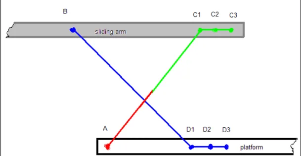
The evolution of each joint’s position in the arm linkage mechanism described above is shown in the Figure 3.9. More exactly, the possible positions are the following:
1) ABC1D1 – the maximum height position – the arms are completely streched; 2) ABC2D2 – intermediary height and position
3) ABC3D3 – the 0 position – the arms are fully folded in horizontal position aligned
with the sliding arms and the platform.
Figure 3.9 Evolution of the sliding joints relative to their support.
The support is thus sustaining one secondary arm(sliding joint) and the main
arm(rotating one) which is connected to the actuation device that will be defined in a separate chapter.
3.5.2.b The translation mechanism.
The translation mechanism refers to the sliding of the platform from/towards the storage space, in our case, the bus floor. As we mentioned before, the supports of the platform are sliding on a shell casing from the storage level, that also contributes to the stability of the device.
The sliding device will be mounted on the shell casing as an intermediary between the latter and the platform.
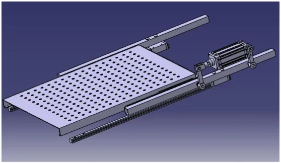
The mechanism that will ensure this translation will be a sliding mechanism, connected to an electric motor, with a proper design that will fit the space(Figure 3.10). It will follow the principle of supporting the sliding arms and translate them along the maximum stroke until outside of the bus.
Once the supports are completely outside the bus, the main mechanism is ready to be actuated. A draft of the mechanism it modeled in the Figure 3.10.
Figure 3.10 3D model of the assembly - Translation motion
3.5.2.c Ramp-movement mechanism.
Another important aspect is the ramp that will be mounted on the front side of the platform for the following reasons:
- connection of levels: it connects the platform with the ground floor when the passenger gets on or out of the platform(Figure 3.11).
- safety: except the moments when it connects the levels, it is stored in vertical position to ensure the safety of the person in the wheelchair during the lifting and descending operations.
The ramp will go down when the platform reaches the ground level at the signal of a sensor of proximity and will be lifted in vertical position after the person in the wheelchair gets on the platform/gets out of the platform.
The way in which this actuation will be done will be discussed in a the actuation technology chapter.
The platform will have to be as light as possible, resistant and eliminate slippery effects.
4 Dynamic computations
4.1 Pre-dimensioning
Before starting the construction and analysis of the model itself, we need to
pre-dimension a series of parts, which will influence the dynamic results. It is to be specified that, our dimensioning refers strictly to lengths, not to thicknesses of parts. This is because the next chapter of our project will feature a dynamic analysis of the system, phase in which the thicknesses of the parts will not yet be required. They will be further calculated in a Finite Element Analysis, when also the materials will be chosen.
What we know so far from the point of view of dimensions are the dimensions of the platform itself and the height from the floor bus to the ground level. The dimensions of the platform are also chosen, based on various reasons: the official legislation that imposes the minimum available space required by the movement and lifting of a
wheelchair, the space available inside and below the bus, comparison with other similar products. Thus, based on these facts, the dimensions of the platform are:
Lplatform=1200 mm
Wplatform=850 mm.
The second known parameter is the height from the floor bus to the ground level, and it is taken from the dimensions of the actual bus:
Table 4.1 Dimensional requirements
What we know What we need to find
Height of the floor of the bus Length of the platform
Width of the platform
Length of the principal arm Length of the secondary arms Height at which the cylinder is mounted Distance form the edge of the platform at
which the cylinder is mounted
The selection of the required dimensions is done iteratively. We start by approximating the length of the main actuating arm (principal arm) with roughly half of the length of the platform. This would imply a value of 600 mm, but taking into account that the arm will not be mounted strictly on the edge of the platform, we can set a value of 580 mm. Making the arm longer than this would add more weight to the arms and higher forces and moments due to the effect of the sliding arm beam principle. The distance between the edge of the platform and the main joint of the principal arm is 50 mm.
Knowing the length of the principal arm we can set the dimension of one secondary arm, being half of the length of the principal arm, i.e. 290 mm.
The length of the supports on which the arms are mounted (sliding arms) must be of at least 1200 mm, so that they travel the distance the platform travels, and still remain inside the bus, with the possibility of supporting the piston on it. For stability reasons it’s better to have sliding arms as long as possible, in the case we choose to fix them in 2 points on the sliding system. Otherwise, if we keep them fixed on the sliding system in only one point, the total length should be less. This will depend entirely on the sliding system chosen, so for the moment, the length of the sliding arms is not settled.
Another aspect about the pre-dimensioning regards the placement of the actuation system (hydraulic cylinder). The higher is the distance from the lever in horizontal position to the rod of the piston, the lower are the reactions that are transmitted in the main lever, and also a lower piston force is required. As advantageous as it may seem to place the piston as high as possible, we need to remember that the actuation system will be inside the bus, and this way it could restrict the space inside and maybe interfere with other equipment.
4.2 Introduction to ADAMS
Having to deal with such a complex system of motions, a dynamic analysis is necessary, so that we can simulate the full-motion behavior of our model with respect to time. This analysis will be performed using the software ADAMS, Automatic Dynamic Analysis of Mechanical Systems.
ADAMS allows testing virtual prototypes and optimize designs for performance, safety, and comfort, without having to build and test numerous physical prototypes. It contains a core package that permits to import geometry from most major CAD systems or to build a solid model of the mechanical system. A full library of joints and constraints is available for creating articulated mechanisms. Once the virtual prototype is complete, ADAMS checks the model and then runs simultaneous equations for kinematics, static, quasi-static, and dynamic simulations. Results are viewable as graph, data plots, reports, or animations that can be easily shared in different formats. One can use the results (loads created from different types of motion) of ADAMS simulation studies to provide loads for many different FEA programs to optimize the structure of a design.
There are 4 main steps that describe the Functional Virtual Prototyping Process, and these steps are the same steps that would be used to build a physical prototype, i.e
Step 1. Build the virtual model
The model in ADAMS/View can be created by:
geometry and realistically view the behavior of the model, which is also the case of our work. Each part was previously drafted in CATIA, and then exported with the extention .stp in order to be imported directly in ADAMS.
Figure 4.2 Geometry of the main mechanism
The parts’ geometries have zero influence on the dynamic of the mechanism. Importing the parts or creating them in ADAMS is useful when creating animations, so that one can get better 3D-views of the behavior. The scissors mechanism that we have to build is symmetric with respect to Y axis and its movements will take place in the XY plane.
However, the actuating system is positioned only one side with respect to this axis, but this will have little influence among the results. The mass of the cylinder is very small in comparison with the mass of the entire system, and moreover can be supported in other directions than the sliding arm. The force that is exerts will be transmitted on the other side by means of the principal arm. This principal arm will have a special geometry, that will be further on discussed. Below is the result of the assembly of the parts that were imported from CAD, specifically:
- 2 Sliding arms - 1 Main arm - 4 Secondary arms - Platform
The geometry of parts is only drafted partially, later on, each part will suffer modifications in thickness, width and shape, but the lengths are kept the same.
Adding constraints and motions to mandate part movements. There is a multitude of constraints that can be added, but for our case the most accessible solution was to use idealized joints, that are mathematical representations of joints that have physical counterparts, such as a revolute (hinge) or translational joint. The joints and their location are the factors that influence the dynamic performance of the system. They are attached to parts, in whatever location is desired (as long as they fulfill the motion), but are preferable to be also positioned in what ADAMS defines as Markers.
Markers define a local coordinate system on any part (flexible, rigid, curve, or ground) in the model. A marker has a location (the origin of the coordinate system) and an orientation. ADAMS/View automatically creates markers at the center of mass of all solid geometry and at anchor points on geometry that define the location of the object in space. They can be translated, rotated, copied to any favorable position. Renaming the markers eases the identification of each marker associated to particular joints. For complex systems is recommended to rename each part, marker, joint.
Having presented the components, we can present now a logical connection between each component, and what type of joint connects them. This is shown in Figure 4.3.
Example (based on Figure 4.3):
Let’s take the case of the sliding arm. It is connected trough a hinge with the cylinder and the principal lever, and a translational joint with the slider (an additional part that allows the translational and rotational movement of the lever with respect with the sliding arm). The connection between the sliding arm and the sliding system is
illustrated into two branches. One of them expresses the translational joint between the two of them, and the other one expresses the motion imposed in this translational joint. In ADAMS, no system can work without applying motions.
These motions are essential for the mechanism and define the trajectories of each part. They can be of three types: Displacement, Velocity, Acceleration; this means that, depending on the function that the user inputs, the program will induce a variation of displacement, velocity or acceleration function of time. Motion implies space variation with time, so before defining our functions we should have a rough idea regarding the repartition in time of each motion. Nevertheless, this repartition is done strictly for analysis purposes, and is likely to be modified further on.
Repartition in time of each motion
0…5 seconds : Horizontal movement to take the platform outside the bus
5…8 seconds : Vertical movement to lower the platform reaching the ground level 8…13 seconds : The platform remains on the ground, waiting for the passenger to go on it
13…16 seconds : Vertical movement to lift the platform and the passenger at the level of the bus
16…21 seconds : Horizontal movement to take the platform along with the passenger inside the bus.
Our system is defined using two motion functions. One attached to the virtual sliding mechanism that takes the platform outside the bus, and the other one attached to the hydraulic cylinder and which simulates the stroke of the rod.
Table 4.2 Motion functions
Function Syntax Result
Sliding mechanism
IF(time-5:1250*sin(π/10*time),1250,
IF(time-16:1250,1250,1250*sin(π/10*(time-11))))
From time 0 to 5 the platform goes outside the bus;
From time 16 to 21 the platform goes inside the bus Cylinder IF(time-5: 0, 0, IF(time-8: (-25*COS(PI/3*(time-5))+25), 50, IF(time-13:50, 50, IF(time-16:(-25*COS(PI/3*(time-16))+25), 0, 0))))
The rod of the cylinder travels the stroke only between time 5 to 8 and 13 to 16
Friction coefficients
Adding friction to each movable joint is permitted in ADAMS, and also recommended, because this way the numeric results are closer to the real case. The power consumption is greatly influenced by the friction forces that appear during the motions, increasing accordingly with the friction coefficients. It is ideal to minimize the friction as much as possible, so that the power consumption for each motion is lower.
Figure 4.4 Friction parameters for different joint types
Adding friction to revolute joints. Joint reactions, bending moment and torque preload
determine the frictional torque in a revolute joint. They are not compulsory, and can be turned off. The joint reactions are converted into equivalent torques using the respective friction arm and pin radius. The joint bending moment is converted into an equivalent torque using pin radius divided by bending reaction arm.
Adding forces to translational joints. Joint reaction force, bending moment, torsional
moment, and force preload are used to compute the frictional force in a translational joint. One can individually turn off the force effects.
But the only way to determine the accurate coefficient of friction between two materials is to conduct complex experiments. This is why, the values introduced in ADAMS are only an approximation of the real cases, and can be used only as guidance for the obtaining of results values comparable with the real case. After a brief research
regarding the values of the coefficients of friction between different materials, we set the following values for our mechanism:
- Friction coefficient in the sliding system: 1.2- dry sliding - Friction coefficient in the piston: 1.05
- Friction coefficient in the joints between the principal lever and the secondary levers: Steel on Steel: 0.57
Adding Forces that Induce or Resist Part Movements. These forces will affect part motion and reaction forces on constraints. In our system we defined an Applied Force to
This is done using the Function Builder in the Applied Force setup menu, and defining a “STEP” function. This function is an approximation of the Heaviside-function with a cubic polynomial. The syntax for this function is:
STEP (x, Begin At, Initial Function Value, End At, Final Function Value)
Applied in our case, we get
F(t)= -step(time,10,0,11,4000).
It sets the force to come in action immediately after the platform has descended onto the ground, and has stabilized completely, and to last until the platform is entirely inside the bus. At time 10 seconds the force begins to actuate on the platform, reaching a value of 4000 N until the 11th second, and preserving the same value during the remaining time until the mechanism stops.
Step 2. Test the virtual model
After we have created the desired model or at any point in the modeling process, we can run tests of the model to ensure that it was created correctly and to verify its
performance characteristics and its response to a set of operating conditions. Adams/Solver formulates and solves the equations of motion for the model,
simultaneous with the display of an animation of the model in motion and displays strip charts tracking the measures previously specified.
Before running any type of simulation, a static equilibrium simulation is required. Performing a static simulation on the model. ADAMS/Solver iteratively repositions all the parts in an attempt to balance all the forces for one particular point in time. Each static simulation is independent of the time-varying effects of velocity and acceleration. Therefore, no inertial forces are taken into account. A positioning of parts for which all forces balance is known as an equilibrium configuration.
There are three types of simulation from which one can choose: static, kinematic or dynamic simulation. The choice between these types of simulations depends on the user, and what is the purpose of the analysis. For our simulation we set the program to
perform a dynamic analysis.
This dynamic simulation is a time-history solution for all displacements, velocities, accelerations, and internal reaction forces in the model driven by a set of external forces and excitations. During a dynamic simulation, ADAMS/Solver solves the full set of non linear differential and algebraic equations (DAEs). It is the most complex and
computationally demanding type of simulation and is meant to be used with models that have one or more degrees of freedom. Unlike kinematic and static simulations, which
involve the solution of only algebraic equations, dynamic simulations are more complex because they involve the solution of differential and algebraic equations (DAEs). Two basic types of algorithms are available in ADAMS/Solver to perform the numerical integration required for dynamic analyses:
Stiff solution methods that use implicit, backward difference formulations (BDF) to solve the DAEs.
Non-stiff solution methods that use explicit formulations to solve ordinary differential equations (ODEs) that are obtained from the DAEs by way of coordinate partitioning methods.
There are other simulation parameters that can be set.
- The duration of the simulation, which can either last for a stated time, or end at a stated time. The frequency of the simulation (in steps/second) represents the total number of times ADAMS/View should provide output information over the entire simulation. In our case, the number of steps is 840, on a total time of 21 seconds of the total time of one cycle of the mechanism. This leads to a frequency of 40 steps/second.
- Measures. A measure allows investigating several predefined and user-defined
characteristics of the model during or after a simulation. Each object in the model can be measured and can give different measurable characteristics. In the table below are the objects and their characteristics that were of interest for our project and which will be shown and explained later on.
Table 4.3 Results that can be found when simulating a model
Joint motion, general point motion Power consumption Element force Element torque Translational displacement Translational velocity Translational acceleration Angular velocity Angular acceleration Projection angles Joint constraint, joint primitive constraint Element force Element torque Translational displacement Translational velocity Translational acceleration Angular velocity Angular acceleration Projection angles Rigid body CM Position CM Velocity CM Acceleration CM Angular Velocity CM Angular Acceleration Kinetic Energy Translational Kinetic Energy Angular Kinetic Energy Translational Momentum Angular Momentum Potential Energy Variation
Step 3. Review the model
The results of the simulation can be viewed and interpreted by plotting them in an ADAMS module called ADAMS/PostProcessor. ADAMS/PostProcessor permits the plotting all of the measures that had been specified, as well as plot the result
components that ADAMS/View automatically generates during a simulation.
Static analysis
Before presenting the results obtained during the dynamic simulation ran in ADAMS, we will present a static analysis, which includes the balance of forces, the sum of moments with respect to several points, and the static matrix. Figure 4.5 shows the platform, the main arm and the two secondary arms, and the reactions that exist in each joint. We will use the same joint notations in ADAMS as we used at this point.
Figure 4.5 Forces acting upon our mechanism
a=290 mm [length of the secondary arm]
b=150 mm [height at which the piston is mounted]
c=20 mm [distance from the edge of the platform to the joint] G=4200 N [maximum force on the platform
Principal arm: ΣXi=0 : HA0+HA+HB=0 ΣYi=0: VA+VB+VC=0 ΣMiA=0 : -b·HA0+a·VB+2a·VC=0 Secondary arms: ΣXi=0 : HD-HB=0 ΣYi=0: VD-VB+VE=0 ΣMiB=0 : -a·VD+a·VE=0 Platform: ΣXi=0 : -HD=0 ΣYi=0: -VD-G-VC=0 ΣMiD=0 : -a·G-2·a·VC=0
Table 4.4 Balance of moments and forces
HA0 HA HB HD VA VB VC VD VE V X 1 1 1 0 0 0 0 0 0 0 Y 0 0 0 0 1 1 1 0 0 0 M_A -b 0 0 0 0 a 2a 0 0 0 X 0 0 -1 1 0 0 0 0 0 0 Y 0 0 0 0 0 -1 0 1 1 0 M_D 0 0 0 0 0 0 0 -a a 0 X 0 0 0 -1 0 0 0 0 0 0 Y 0 0 0 0 0 0 -1 -1 0 G M_D 0 0 0 0 0 0 -2a 0 0 aG 1 2 3 HA0=-16240 N HA=16240 N VA=4055.172 N RA HA2 VA2 =16738 N M 1 0 b 0 0 0 0 0 0 1 0 0 0 0 0 0 0 0 1 0 0 1 0 0 0 0 0 0 0 0 1 0 0 1 0 0 0 1 0 0 0 0 0 0 0 0 1 a 0 1 0 0 0 0 0 1 2a 0 0 0 0 1 2 a 0 0 0 0 1 a 0 1 0 0 0 0 0 1 a 0 0 0 v 0 0 0 0 0 0 0 G 2ac ( ) G lsolve M v( ) 16240 16240 0 0 4055.172 289.655 4344.828 144.828 144.828
HB=0 N VB=289.655 N VC=-4344.828 N VD=144.828 N HD=0 N VE=144.828 N Dynamic analysis.
We can structure the results obtained into 4 categories: a) Results showing motion paths of principal parts
b) Results showing the variation of the velocities and accelerations c) Results showing the reactions and torque in each joint
d) Results showing the power consumption for each motion
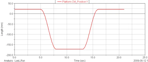
a) The motion paths. Our mechanism has a plane motion, not a three-dimensional one, so, the directions on which parts move can be either X direction, or Y direction. The X direction is the axis along the platform, horizontal, on which the sliding motion occurs. The Y direction is defined as the vertical direction on which the platform will descend in order to lower the passenger in the wheelchair. The first two diagrams describe the trajectory of the platform along the 2 axis.
Figure 4.7 Position of the platform on Y direction with respect to time
Another useful piece of information we can subtract from the motion path graphs is the minimum sliding distance the secondary arms travel on the platform and sliding arms. According to Figure 4.8, when the platform starts to descend, the secondary arms tend to travel backwards from the direction of the platform. When the platform ascends, the process is reversed.
Figure 4.8 The sliding distance graph shows how much the connecting link slides in the special groove. The value is about 34 mm.
We pictured below also the path the cylinder rod travels, because it will help us choose the hydraulic cylinder that we will use, considering also the stroke of the cylinder. From the graph, we now know that the rod travels a distance of 50 mm from when the
Figure 4.9 Position of the rod on X direction with respect to time
Figure 4.10 The evolution on X direction with respect to time of the two secondary levers *All the graphs are plotted with respect to the global coordinate system, thus the starting point on the vertical axis is not 0, but the value at which the part is located in the global coordinates.
b) Variation of velocities and accelerations.
ADAMS/Solver calculates the velocity and acceleration data (the first and the second derivatives of the displacement of the I marker with respect to the J marker) in the global coordinate system. This can be changed by specifying a reference marker, around which ADAMS/Solver will compute all the components of the velocities and
Figure 4.11 Velocity of the platform on the X and Y directions versus time
Figure 4.12 Acceleration of the platform on the X directions versus time
Figure 4.13 Velocity of the rod with respect to time
Figure 4.14 Acceleration of the rod with respect to time
Figures 4.13 and 4.14. Between 0 to 5 seconds and 16 to 21 seconds the velocity and the
acceleration of the rod is higher, because it moves at the same time with the piston and the platform. Between 5 to 8 seconds and 13 to 16 seconds the rod drives the principal arm with a small velocity.
The highest velocity in the system is of 0.4 m/s, which may appear quite high for such an application, but nevertheless this value is normal to be high at the beginning of the motion, due to the inertial forces.The overall velocity can be lowered by modifying the laws of motion and the time duration of each in particular. The values obtained are purely experimental and are referred to as only guidelines.
Each increase in speed leads to an acceleration regime, and each decrease in speed leads to a deceleration of the system. According to the graphs, the platform decelerates when it comes out of the bus, accelerates when it descends, decelerates when it ascends and accelerates when it goes back inside the bus.
c) Reactions and torque.
Each reaction and torque has three components, corresponding to the three directions. One can find and plot the resultant of these components by computing the square root of the sum of the squares of each component. The forces and torque in our system have only one plane components, on X and Y. The joints in which we are interested are the ones denoted with A0, A, B, C, D, E, because based on the following graphs we can
make a comparison between the values obtained in the static analysis and the values obtained in the dynamic analysis.
Figure 4.15 Reactions on X and Y directions in joint A0 versus time
Figure 4.17 Torque characteristic of joint A with respect to time
Figure 4.18 Reaction on Y direction in joint B versus time
Figure 4.20 Reaction on Y direction in joint C versus time
Figures 4.21 Torque characteristic of joint C with respect to time
Figure 4.23 Reaction on Y direction in joint E versus time
All graphics that plot the evolution of the forces in different joints show a sudden increase at time=10 seconds. That is the moment when the maximum force of 4200 N is applied in order to simulate the effect the passenger in wheelchair has on the platform. The force in joint A0 is actually the force required by the piston to lift the maximum
load. The most loaded joints are A (because the piston force is directed transmitted through the principal arm extension) and C. Special care must be taken when designing the joint components (either bearing or bushing with fluid friction or dry friction).
The maximum torque in the system is in joint A, but close to this value is, as expected, the joint that unites the principal arm with the two secondary arms (joint denoted with B). It is recommended to choose the materials in these joints carefully, and perform a strength analysis in order to determine the proper width and thickness of the arms, to that they can undergo forces and moments of this magnitude.
d)Power consumption for each motion
The translation mechanism clearly takes less power than the lifting mechanism, both increasing abruptly when the platform is loaded. The piston results in a power consumption of 430 Watt at most, while the sliding system has a maximum power consumption of 170 Watt. The higher the friction forces in the system, the higher the power consumption (See Section “Building the model” for friction coefficients).
Figure 4.24 Power consumption of the piston with respect to time
Figure 4.25 Power consumption of the sliding system with respect to time
Remark: We notice a correspondence between the values of the forces obtained in the
static analysis with the values obtained in the dynamic simulation. However, the
dynamic simulation yields higher values, because in this type of analysis the masses and inertial forces are taken into consideration, unlike in the static analysis.