Master’s Degree in Sound and Image
Production of 3D Animated Short Films in Unity 5:
Can Game Engines Replace the Traditional Methods?
Specialization in Computer Animation – 2016/17
Luís António Gomes Tarrafa Ramos
Supervisor: Doutora Sahra Kunz Co-Supervisor: Mestre André Cruz
iii
Dedication
I dedicate this work to my parents António Ramos and Cristina Ramos, who trusted me by giving me the opportunity to continue studying and without whom none of my academic progress would have been possible, and to Ânia Guerra for all the support she gave me and for always trying to cheer me up when I needed it.
iv
Acknowledgements
I would like to thank Sahra Kunz and André Cruz, this work’s supervisor and co-supervisor respectively, for all the support and orientation provided during the development of this dissertation. I also acknowledge all the elements of Universidade Católica Portuguesa that were directly or indirectly involved in the development of this work or contributed in any way to its success.
I would like to thank everyone that gave me moral support or useful critique and suggestions during the development of this dissertation.
v
Abstract
In 3D animation cinema, the elements of a scene are created by artists using computer software. To generate the final result, there must be a conversion (rendering) of the three-dimensional models to two-three-dimensional images (frames) that will later be joined together and edited into a video format.
3D animation films have traditionally been rendered using pre-rendering engines, a time consuming and expensive process that usually requires the use of multiple computers rendering at the same time (render farms), renders which may need to be repeated if the results are not ideal.
Videogames, on the other hand, are reactive applications where the player may have different possible courses of action that will generate distinct results. In those cases, it is necessary that the engine waits for the player’s input before it calculates the following frames. To allow for fast calculations in real time, 3D game developers use game engines that incorporate real time rendering methods which can generate images much faster than the pre-rendering engines mentioned above.
To be able to generate a large number of frames per second, there must be an optimization of the entire scene, in order to reduce the number of necessary calculations. That optimization is created by using techniques, practices and tools that are not commonly used by animation cinema professionals.
Due to that optimization necessity, videogames always had a lower graphic quality than that of animated films, where each frame is rendered separately and takes as long as necessary to obtain the required result.
Physically Based Rendering (PBR) technology is one of the methods incorporated by some rendering engines for the generation of physically accurate results, using calculations that follow the laws of physics as it happens in the real world and creating more realistic images which require less effort, not only from the artist but also from the equipment. The incorporation of PBR in game engines allowed for high graphic quality generated results in real time, gradually closing the visual quality gap between videogames and animated cinema.
Recently, game engines such as Unity and Unreal Engine started to be used – mostly by the companies that created the engine, as a proof of concept – for rendering 3D animated films. This could lead to changes in the animation cinema production methods by the studios that, until now, have used traditional pre-rendering methods.
vi
Resumo
No cinema de animação 3D, os elementos de uma cena são criados por artistas através da utilização de programas de computador. Para gerar o resultado final, é necessário fazer-se uma conversão (render) dos modelos tri-dimensionais para imagens bi-dimensionais (frames), que posteriormente serão unidas e editadas para um formato de vídeo.
Tradicionalmente, o rendering de filmes de animação 3D é feita através de motores de
pre-rendering, um processo demorado e dispendioso que geralmente requer a utilização de
múltiplos computadores a trabalhar em simultâneo (render farms), e que poderá ter que ser repetido caso os resultados obtidos não sejam ideais.
Os videojogos, por outro lado, são aplicações reactivas, onde o jogador pode ter várias sequências de acções, que poderão gerar resultados distintos. Nesses casos, é necessário o motor de jogo esperar pela acção do jogador antes de calcular as imagens seguintes. Para possibilitar cálculos rápidos em tempo-real, os criadores de jogos 3D usam motores de jogo que incorporam métodos de renderização em tempo-real que conseguem gerar imagens muito mais rápido do que os motores de pre-rendering mencionados acima.
Para conseguir gerar um grande número de imagens por segundo, é necessário existir uma optimização de toda a cena, para reduzir o número de cálculos necessários. Essa optimização é criada através da utilização de técnicas, práticas e ferramentas que, geralmente, não são utiliadas por profissionais da área de cinema de animação.
Devido a essa necessidade de optimização, os videojogos sempre tiveram uma qualidade gráfica inferior à dos filmes de animação, onde o render de cada imagem é gerado separadamente e pode levar tanto tempo quanto for necessário para obter o resultado desejado. A tecnologia de Rendering Baseado em Física (Physically Based Rendering – PBR) é um dos métodos incorporados por alguns motores de rendering para a geração de resultados físicamente correctos, usando cálculos que seguem as leis da física, tal como acontece no mundo real e criando imagens mais realistas necessitando de menos esforço, não só da parte do artista mas também do equipamento. A incorporação de PBR em motores de jogo possibilitou resultados gerados em tempo-real com grande qualidade gráfica, o que gradualmente vai aproximando a qualidade visual dos videojogos à do cinema de animação.
Recentemente, motores de jogo como o Unity e o Unreal Engine começaram a ser utilizados – maioritariamente pelas companhias que criaram o motor de jogo, como prova de conceito – para renderização de filmes de animação 3D. Este passo poderá levar a mudanças nos métodos de produção do cinema de animação em estúdios que, até agora, utilizaram métodos de pré-renderização tradicionais.
vii Table of Contents List of Figures ... 1 List of Abbreviations ... 3 1. Introduction ... 5 1.1. Subject of Investigation ... 5 1.2. Methodology ... 5
1.3. Structure of the Dissertation ... 6
2. State of the Art ... 7
2.1. The Rise of Animation Cinema and Technology ... 7
2.1.1. Animated Films ... 8
2.2. Real-Time Rendering Engines ... 9
2.2.1. 3D Game Engines ... 9
2.2.2. Pre-Rendering vs Real-Time Rendering ... 10
2.3. Physically Based Rendering ... 11
2.3.1. Light Mechanics in PBR ... 14
2.4. 3D Animated Film Production Technologies ... 17
2.4.1. Modelling and Sculpting ... 17
2.4.2. Rigging ... 19
2.4.3. Animation ... 22
2.4.4. Textures and Maps ... 23
2.4.5. Lighting and Rendering ... 23
2.4.6. Post-Production and VFX ... 25
2.4.7. Other Technologies and Techniques ... 27
2.5. Real-Time Rendered Short Films ... 27
2.5.1. The Gift (2016) – Marza Animation Planet Inc. ... 27
2.5.2. Adam (2016) – Unity Technologies ... 28
2.6. Chapter Conclusion ... 30
3. Analysis of the Production Pipeline ... 32
3.1. Traditional Pipeline Overview ... 32
3.1.1. Pre-Production ... 32
3.1.1. Production ... 33
3.1.1. Post-Production ... 35
viii
3.2.1. Software Set-Up ... 35
3.2.2. Creating 3D Assets ... 35
3.2.3. Textures ... 36
3.2.4. Rendering Paths ... 36
3.2.5. Lighting and Cameras Set Up ... 37
3.2.6. Animation Sequencing Method ... 38
3.2.7. Other Optimization Methods ... 38
3.3. Modelling ... 38
3.4. Procedural Asset Creation and Animation ... 40
3.4.1. Physics and Simulation ... 41
3.5. Rigging and Animation ... 42
3.6. Materials and Textures ... 43
3.6.1. PBR Workflow ... 43
3.7. Lighting and Light Baking ... 45
3.7.1. Light Types ... 45
3.7.2. Global Illumination and Light Baking ... 45
3.7.3. Light Probes and Reflection Probes ... 46
3.8. Rendering ... 47
3.8.1. Single-Pass Rendering ... 47
3.8.2. Multi-Pass Rendering ... 47
3.9. Sound and Post-Production ... 48
3.9.1. Sound ... 48
3.9.2. Image Effects and Shaders ... 48
3.9.3. Lookup Textures (LUTs) ... 49
3.10. Chapter Conclusion ... 49
4. Final Conclusions and Future Work Perspectives ... 51
4.1. Comparison Summary ... 51
4.2. Final Product Analysis ... 51
4.3. Is Real-Time Rendering a Viable Option? ... 52
4.4. The Future of Animated Cinema ... 52
References ... 53
ANNEX A – 3D Production Pipeline ... 62
ANNEX B – PBR Workflows ... 63
1
List of Figures
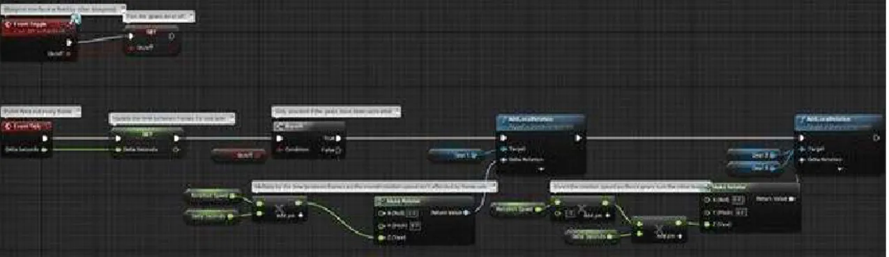
Fig. 1 Unreal Engine 4 blueprint example, retrieved from https://docs.unrealengine.com/latest/INT/Engine/Blueprints/ on June 21, 2017. Copyright Epic Games, Inc. (2017) ... 10
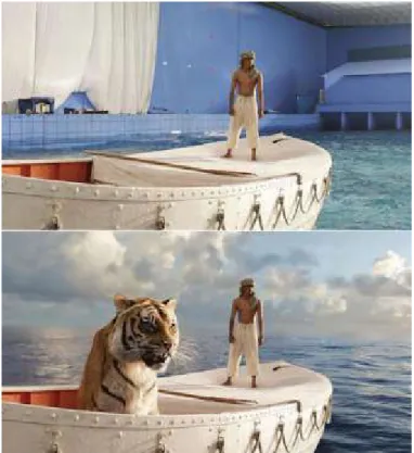
Fig. 2 Life of Pi (2012) screen capture, before and after VFX, retrieved from
https://digitalsynopsis.com/design/movies-before-after-green-screen-cgi/ on June 21, 2017. Copyright Digital Synopsis (n.d.) ... 12
Fig. 3 Raytracing visual representation, retrieved from
https://blog.codinghorror.com/real-time-raytracing/ on June 21, 2017.
Copyright Atwood, J. (2008) ... 13
Fig. 4 Light interaction, retrieved from
https://www.marmoset.co/posts/basic-theory-of-physically-based-rendering/ on June 21, 2017. Copyright Russell, J. (2015) ... 15
Fig. 5 Light interacting with microsurface detail, retrieved from Light and Matter:
The Theory of Physically-Based Rendering and Shading, vol. 1 on June 21, 2017. Copyright McDermott, W. (2015) ... 16
Fig. 6 Facial edge flow in 3D modelling, retrieved from
http://area.autodesk.jp/column/tutorial/character_arpeggio/01_modeling/
on June 21, 2017. Copyright Akasaki, H. (2016) ... 18
Fig. 7 Character rig in Autodesk Maya, retrieved from
https://cgi.tutsplus.com/tutorials/modelling-rigging-a-cartoon-parrot-in-maya-part-9--cms-23933 on June 21, 2017. Copyright Kumari, S. (2015) ... 20
Fig. 8 Rig control curves, retrieved from
https://animationblog.wordpress.com/2016/01/28/r-d-blog-week-2-part-2/
on June 21, 2017. Copyright aneesharai22 (2016) ... 21
Fig. 9 Animation interpolation, retrieved from Multiresolution Mean Shift
Clustering Algorithm for Shape Interpolation on June 21, 2017. Copyright
Chu, H.-K., & Lee, T.-Y. (2009) ... 22
Fig. 10 HDRI example, retrieved from
http://www.lughertexture.com/spherical-hdri-360/spherical-360-nature-trees-plants-sky-hdri on June 21, 2017.
Copyright IuGher (2015) ... 24
Fig. 11 Render passes, retrieved from
http://marcelmarkov.deviantart.com/art/Zbrush-Bust-Render-Passes-337452354 on June 21, 2017. Copyright MarcelMarkov (2012) ... 25
Fig. 12 Marza's tests on the Alembic Importer for Unity, retrieved from Making of
The Gift: Game Changer in Film Production on June 21, 2017. Copyright
Unite Europe (2016)... 28
Fig. 13 Adam's screenshot inside Unity, retrieved from ADAM - Assets Creation for
2
Fig. 14 Storyboard excerpt from Pixar's Brave (2012) feature film, retrieved from
http://pixar-animation.weebly.com/pixars-animation-process.html on June
21, 2017. Copyright Vardanega, J. (2013) ... 33
Fig. 15 Character in the default modelling pose, retrieved from 3D Animation
Essentials on June 21, 2017. Copyright The Basement Design + Motion
(2012) ... 33
Fig. 16 Reflections using LDR and HDR environments, retrieved from
https://gamedev.stackexchange.com/questions/62836/does-hdr-rendering-have-any-benefits-if-bloom-wont-be-applied on June 21, 2017. Copyright
Reed, N. (2013)... 37
Fig. 17 Different Levels of Detail on the same object, retrieved from
http://evgeny-3d.com/3d-modeling/scull.html on June 21, 2017. Copyright Lyapin, E.
(n.d.) ... 40
Fig. 18 Unity's Animator Controller, retrieved from
https://blogs.unity3d.com/2016/08/31/adam-animation-for-the-real-time-short-film/ on June 21, 2017. Copyright Nechevski, K. (2016) ... 42
Fig. 19 Lookup texture in Unity, retrieved from
https://docs.unity3d.com/550/Documentation/Manual/script-ColorCorrectionLookup.html on June 21, 2017. Copyright Unity
3
List of Abbreviations
AO Ambient Occlusion
AR Augmented Reality
BRDF Bidirectional Reflectance Distribution Function
CG Computer Graphics
CPU Central Processing Unity
FK Forward Kinematics
GI Global Illumination
GPU Graphics Processing Unit
HDR High Dynamic Range
HDRI High Dynamic Range Image
IK Inverse Kinematics
LDR Low Dynamic Range
LOD Level Of Detail
LUT Lookup Texture
MoCap Motion Capture
MSAA Multi-Sample Anti-Aliasing
PBR Physically Based Rendering
RGB Red Green Blue
sRGB Standard Red Green Blue
Texel Texture Pixel
Triple-I Information International Incorporated
UE4 Unreal Engine 4
5
1. Introduction
1.1. Subject of Investigation
The main goal of this dissertation is to establish a comparison between two rendering methods used in 3D animation films production: pre-rendering – the traditional method – and real-time rendering, a technology that only recently started being used for animated short films production, and often just as a proof of concept.
The new methods and technologies involved in real-time rendering for film production have the potential to affect the production methods that have been in use for decades, creating a more efficient workflow and allowing for more artist-friendly approaches to some steps of the production pipeline.
By changing the technologies used in animated film production, 3D animation artists may be required to expand their knowledge of game engines and game development in general, while still being able to use their knowledge of traditional rendering methods.
The combination of distinct technological areas or methods can generate new forms of art, such as the incorporation of user interactivity, Virtual Reality (VR) or Augmented Reality (AR) systems in animated films.
Being a recent technology still under development, that could affect the current production methods and change the future of animated cinema, makes this subject worthy of investigation.
1.2. Methodology
In order to create a comparison between the two methods mentioned above, every step of the production pipeline of each method must be analysed and compared, and all the advantages and disadvantages taken into account.
By the end of the research, using the combined collected data from each step, we will be able to conclude in which situations the use of each process will be more advantageous, and possibly speculate if, in the future, there will be room for both methods in large studios, either by using only one of them or by combining the strengths of both.
The research process will follow an explorative and comparative methodology, where the first approach will be a general investigation of existent sources of material and projects developed or in development that relate to the issue being studied. The initial material will be composed of text documents (papers, articles, books, etc.), instructional videos, interviews and/or public talks, and visualization of animated 3D films created using both processes.
This information will compose the first draft of the dissertation, and its analysis will allow for a better planning of the following steps, by showing where there is a lack of information or a need for practical examples.
After these steps are concluded, a more in-depth approach will be taken in the investigation of specific techniques or technologies used in each method, detailing the
6
production pipelines commonly used or analysing other methods that could accomplish a specific goal or result.
The final data will be condensed and combined, and then be put through a critical analysis process in order to reach relevant conclusions.
1.3. Structure of the Dissertation
This dissertation will be divided into three main chapters.
The State of the Art (chapter 2) will be focused on exposing and explaining the existing technology and techniques used in traditional and real-time rendering. This chapter will also introduce the notions and concepts required to understand the following chapters.
The Analysis of the Production Pipeline (chapter 3) will contain an analysis of the production steps used in traditional rendering and use that analysis as a base to compare it with each step to be used in a real-time rendering pipeline.
In Final Conclusions and Future Work Perspectives (chapter 4), the data collected in chapter 3 and the conclusions taken from it will be reviewed and condensed into a critical analysis to reach conclusions regarding the advantages, disadvantages and the future of real-time rendering in 3D animated short films production.
7
2. State of the Art
2.1. The Rise of Animation Cinema and Technology
There are two primary industries using 3D animation today: the entertainment industry, which is the most recognized and includes film, television, video games and advertising, and the scientific industry, which includes medicine, law, architecture and product visualization. 3D animation is a very recent technology, and new ways of using it are constantly appearing, such as augmented reality, using 3D to create art such as sculptures, and projection mapping (Beane, 2012, pp. 2-10).
Despite that most of the technologies being used today by the 3D animated film industry have been developed before the 21st century, from 3D animation software and ray-tracing
rendering technology to real-time rendering engines1. Nowadays, the majority of the
developments in 3D animation technology are improvements of already existing processes in terms of efficiency and capabilities, along with the development of the hardware used in the production of 3D animation. These developments allow the artists to create more realistic and complex models, simulations and animations with less effort.
The terms Computer Graphics (CG) and Computer Animation were created in the 1960s. The term Computer Graphics is credited to William Fetter in 1960. 3D computer animation and rendering, and many of the techniques we still use today were only invented in the 1970s. In this decade, the first 3D animation studios were created, such as Information International Incorporated (Triple-I), Robert Abel and Associates, Digital Effects, and Lucasfilm which also had a CG division called Graphics Group which would eventually become Pixar (Beane, 2012, pp. 10-19).
“This decade [1960s] is when we saw the computer evolve from a strictly calculating device into a tool that allowed for creation and change.” (Beane, 2012, p. 11)
The first commercially available 3D animation software was created by Wavefront Technologies in 1984. Before that, companies that created 3D animation needed to write their own proprietary software. It was only in the 1990s that 3D graphics began to be used in video game consoles, with the release of the Sony Playstation and Nintendo 64 systems (Beane, 2012, pp. 10-19), with one of the most relevant games being Legend of Zelda: Ocarina of Time (1998, Nintendo 64) (Kerlow, 2004, p. 28).
In the late 1990s and beginning of 2000s, films began to have more complex digital effects. Terminator II (1991) had approximately 150 visual effects shots, Batman Forever (1995) had around 250, Titanic (1997) had close to 550, Armageddon (1998) had around 240,
Godzilla (1998) had close to 400 and How the Grinch Stole Christmas (2000) had around 600
(Kerlow, 2004, p. 27).
Since then, 3D animation technology in films and advertising has become so realistic that most people cannot notice they are looking at a CG object or effect (Beane, 2012, pp. 10-19).
1 Vd. chapters 2.2 – Real-Time Rendering Engines and 2.3 – Physically Based Rendering and respective
8
2.1.1. Animated Films
Pixar is one of the most influential animated film studios in the history of 3D animated cinema. Pixar’s Toy Story (1995) was the first animated feature film to be entirely created with three-dimensional computer animation techniques (Kerlow, 2004, p. 26), and it was a huge success. It was expected to get a return of $100-200 million, and although it had only a budget of $30 million and only 110 staff members, it had a worldwide gross of $362 million. The technology was not yet fully developed, but the captivating story and characters made up for it. The film took around 800 thousand machine hours to render – 2 to 15 hours per frame (Bettinger, 2017, paras. 3-15).
George Lucas and Industrial Light & Magic had already revolutionized the film industry with their first Star Wars trilogy (1977-83), and they did it again in the prequels trilogy (1999-2005) by using digital effects and computer animated 3D characters and environments in a live-action film (Lobo, 2014, paas. 5-8). In Star Wars: Episode II (2002) there were 2200 visual effects shots, with 10200 visual effects elements, 5 million frames, 929 animated shots, and a crew of over 250 digital artists (Kerlow, 2004, p. 30).
The prequels were not well received by the fans due to the excess of computer animated characters, although just 2 years after the first movie of the prequel, Lord of the Rings (2001) introduced a very well received Gollum character which was almost entirely created with CGI (Lobo, 2014, para. 6), while also accomplishing great results with crowd simulation (Beane, 2012, pp. 10-19). Despite the unwillingness of many cinema lovers to accept that visual effects and CGI are the future of cinema, the technological developments in these areas have reached the point where most people cannot make out if a visual element is a practical or a visual effect. However, although the quality of visual effects has improved immensely in just a few years, there is still a long way to go until we can create believable humanoid CGI characters (Lobo, 2014, paras. 18-19).
Monsters Inc. (2001) was a very successful film, with a worldwide gross of $525
million. It had a lot of technological improvements relative to Pixar’s first film, particularly in the physics department (Beane, 2012, pp. 10-19). As stated by the Collider entertainment news website writer Brendan Bettinger (2017, para. 47), there were “2.3 million individually animated hairs on Sulley. It took 11-12 hours to render a single frame with Sulley in it.”
Finding Nemo (2003) took Pixar to another level, with a worldwide gross of $868
million. It was on the top 10 of both domestic and worldwide box office charts, and it broke the first-day record for home-release DVD sales with 8 million copies. By the end of 2006 it had sold 40 million copies (Bettinger, 2017, paras. 51-60).
Up (2009) was another important mark in Pixar’s history, grossing $731 million
worldwide. With Up, Pixar started creating 3D animated films that used the 3D screens technology in the cinemas, and even made re-releases of early films with that technology. It was also the first Pixar movie and the first animated movie since Disney’s The Beauty and the
Beast to be nominated for Best Picture at the Academy Awards (Bettinger, 2017, paras.
108-119).
Toy Story 3 (2010) grossed $1.1 billion, almost three times more than Toy Story (1995).
All the models needed to be remade from scratch for this film, because the old character files could not be opened in the new software (Bettinger, 2017, paras. 120-131).
9
The technology in Monsters University (2013) surpassed previous Pixar movies. There were 400 different monsters in the movie, with the average shot containing more than 25. Sully’s character had 5.5 million individual hairs on his body, double of what it had in Monsters,
Inc. (2001), and 100 million CPU (Central Processing Unit) hours2 were needed to render the
final edit – the film took 2 years to be rendered, using 2.000 computers (Bettinger, 2017, paras. 155-169).
2.2. Real-Time Rendering Engines 2.2.1. 3D Game Engines
“The great popularity and growth experienced by computer games and platform games translated into many jobs for three-dimensional computer animators (…)” (Kerlow, 2004, p.
13)
The most popular 3D Game Engines available to the public today are Unity 5, Unreal Engine 4 (UE4) and CryENGINE. All of them have great graphical capabilities with technologies such as Physically Based Shading and real-time Global Illumination, and include particle systems, physics engines, advanced animation systems, and accept major 3D applications’ file formats.
“Global illumination, or ‘GI’, is a term used to describe a range of techniques and mathematical models which attempt to simulate the complex behaviour of light as it bounces and interacts with the world.” (Unity Technologies, Introduction to Lighting and Rendering,
2017, para. 1)
All the engines are able to produce somewhat similar results, depending more on the skill of the developers than the capabilities of the engine itself. When choosing an engine, unless developing for a specific platform that only one of them supports, developers should experiment with all of them and choose the tool that suits them more.
According to Mark Masters (2014, para. 20), instructor at Pluralsight/Digital Tutors, CryENGINE has the steeper learning curve of the three, with the other two being fairly user-friendly and intuitive – Unity’s interface is very easy to learn and handle, and UE4 includes a new Blueprints visual programming system (see Fig. 1– Unreal Engine 4 blueprint example) that makes it easy for new developers to learn how to create interaction. The node-based Blueprints system allows the designers to use many tools that were previously only available to programmers, such as the creation of materials that update themselves according to the environment, random events, or procedural generation and scattering of objects, just by connecting nodes, events, functions and variables in a logical manner (Epic Games, 2017).
2 CPU time represents the total amount of time a computer has been actively used for a given task (Free
10
Fig. 1 - Unreal Engine 4 blueprint example
While Unity and UE4 are free to use commercially up to a predefined income where a royalty is added, CryENGINE uses a paid subscription model (Masters, 2014, paras. 10, 17, 21).
2.2.2. Pre-Rendering vs Real-Time Rendering
The 3D models are created in a computer, where the artist views them as a mathematical representation of points and surfaces in three-dimensional space. Rendering is the process that translates the modelled 3D assets into 2D images, taking into account the model’s position, materials and the scene’s lighting information to determine the colour of each pixel in the final image (Slick, What is Rendering?, 2017, 3-5).
Traditional rendering engines use many processes, techniques and algorithms that were designed for scenes with complex geometry, lighting and shapes, rather than for real-time performance. They also assume that thousands of samples will be taken in each pixel. Some of these design decisions make the engines less efficient at rendering simple scenes, leading to unnecessary work being done, depending on the scene.
These engines support a high range of geometric primitives. By using a ray tracer3 that
only supports simple shapes such as triangles, by tessellating4 all the complex primitives before
performing intersection tests, many calculations can be avoided, giving substantial advantages in performance, memory usage and reduced system complexity (Pharr, Jakob, & Humphreys, 2016, pp. 110, 136-139)
Rendering can be divided into two major categories: real-time rendering and offline or pre-rendering. Real-time rendering is mostly used in gaming and interactive applications, where images must be generated almost instantly depending on user input (Slick, What is Rendering?, 2017, paras. 7-10). Pre-rendered video can also be used for video games, when the processing power of the system is limited or the desired scene is too complex to be rendered in real-time (Kerlow, 2004, pp. 368-369).
“The ability to render polygonal models in real-time is almost as old as three-dimensional computer animation, but today’s systems offer more realistic rendering and more complex models than what was possible a decade ago.” (Kerlow, 2004, p. 120)
Real-time rendering allows the artists to preview the final output of the assets throughout the whole production pipeline almost instantly. This is a huge advantage, but it has its drawbacks. To be able to render in real time, the whole asset production pipeline must have
3 Vd. chapter 2.3 – Physically Based Rendering for more information about the ray tracing technology 4 Tesselation, in CG, refers to a process used to divide each polygon of a model into smaller parts. It is
often used to divide each four-sided polygon (quad) in a model into two or more polygons with three sides each (triangle), which most graphics software and hardware are optimized to use (NVIDIA Corporation, 2017)
11
that end into account, in order to create optimized models by creating lower resolution geometry, textures, and less complex rigs, and reducing as much as possible the need for expensive calculations from the rendering engine (Beane, 2012, pp. 282-283). In order to create a fluid motion, a minimum of 18-20 frames must be rendered each second (Slick, What is Rendering?, 2017, para. 9). In real-time rendering, a lot of information such as scene lighting is often pre-computed (baked) to improve render speed. Static lights information is baked and mixed into static objects’ textures, reflection maps can also be baked and simulations are pre-calculated and baked into geometry animation (Beane, 2012, pp. 284-285). There are many additional ways to decrease the required processing power in a scene: deleting or avoid modelling parts of models that will not be seen from the camera view, reusing assets as much as possible, creating instances of similar objects rather than copies (Cantor & Valencia, 2004, pp. 268-269), creating different levels of detail for the models and textures that will replace each other depending on the camera distance, or the use of billboards (image maps projected in a flat polygon surface) (Kerlow, 2004, p. 122).
Pre-rendering is used in situations where render speed does not affect the final product usability and/or photorealism is required, such as in the animation industry or visual effects. Each frame takes a long time to render, and higher resolution geometry is often used (Slick, What is Rendering?, 2017, paras. 11-13).
In 2013, the difference in graphics quality between pre-rendered cutscenes in videogames and the actual real-time rendered game was very noticeable. With the evolution of real-time rendering technology, videogames started using in-game graphic quality similar to the pre-rendered cutscenes they had in previous games. As stated by Gearnuke gaming news website writer Khurram Imtiaz (2014, para. 4) when comparing the game The Last of Us for
the Playstation 3 (2013) and the future release of The Last of Us Part II for the Playstation 4
(scheduled to be released in 2017), “The large RAM of PS4 will allow them to finally kill the
pre-rendered cutscenes, resulting in real-time gameplay and cutscenes.”
The convergence of various forms of media is the future of technology. Photorealistic 3D real-time rendering will eventually be used by industrial designers, architects, filmmakers, and other industries, which will lead to an increased sharing of information between fields (Sweeney apud Plante, 2015, paras. 6-8).
The use of game engines is also expanding to other industries, like film and architecture visualization. The hybridization of industries allows professionals to learn from each other, and often question themselves why they have not been using that technology all along. Despite that, a change on workflow in any industry requires time and effort, hence the reluctance of some companies to adapt to new technologies that were not originally designed for their industry, even if the software is more affordable than the one being used by the company (Rawn, 2015, paras. 2, 5).
2.3. Physically Based Rendering
“Fast becoming a standard in the games industry due to increased computing power and the universal need for art content standardization, physically based rendering aims to redefine how we create and render art.” (Wilson, 2015, para. 3)
In the early years of computer graphics (CG), computers were expensive and had limited processing power and memory, which made physics simulation for rendering unfeasible.
12
With the evolution of technology, physically based approaches to rendering started to become viable. In the 1980s, physically based rendering techniques such as ray tracing, global diffuse lighting, and microfacet reflection models were introduced. At this time, CG started being used in the animation and film industry in movies such as Star Trek II: The Wrath of
Khan (1982), Tron (1982) and The Last Starfighter (1984). The lack of computing power and
memory made physically based processes like complex reflection models and global lighting effects unusable, and the use of “fake” lighting by strategically positioning invisible light sources in the scene to create more physically accurate results became an industry standard.
In the 1990s, early physically based rendering systems such as Ward’s Radiance and Slusallek’s Vision systems were released, leading to more interest and investigation in the area, producing more efficient algorithms and processes. In the late 1990s and early 2000s, the need for visual effects artists to incorporate realistic rendered images in video footage in the film industry led to the use of physically based approaches. In the animated film industry, photorealistic rendering is also used to create immersiveness, to make the viewer forget that he/she is looking at an environment that does not actually exist (see Fig. 2 – Life of Pi screen capture, before and after VFX). Some of the more modern rendering engines used in the industry today were released, such as Mental Ray, Arnold, and the new version of Pixar’s Renderman with support for ray-tracing rendering.
Fig. 2 - Life of Pi (2012) screen capture, before and after VFX
The term “Photorealistic Rendering” refers to the generation of images that are indistinguishable from photographs captured by a real camera, or that exactly reproduce the actual scene it is representing. Rendering processes, in the early years of the field, were focused on solving fundamental problems such as determining which objects were visible from a given viewpoint. As solutions to those problems were found and developed, and technology advanced, ideas from transversal fields such as physics, astrophysics, astronomy, biology,
13
psychology, the study of perception and mathematics are increasingly included in rendering algorithms and methodologies (Pharr, Jakob, & Humphreys, 2016, pp. xix-xx).
The three most used rendering techniques are Scanline or Rasterization, Raytracing and Radiosity rendering. Scanline rendering performs calculations based on the assets’ polygons instead of computing the results by calculating each pixel, and is often used in real-time rendering. Raytracing uses virtual rays of light that are emitted from the camera and bounce around the scene, interacting with the objects in its path and calculating the colour of each pixel in the final image (see Fig. 3 – Raytracing visual representation). Radiosity performs calculations without depending on the camera. The calculations are surface-oriented instead of calculating pixel-by-pixel. It is often used in conjunction with raytracing (Slick, What is Rendering?, 2017, paras. 17-18).
Fig. 3 - Raytracing visual representation
Most pre-rendering photorealistic rendering engines use the Raytracing algorithm, which involves following the path of a virtual ray of light though a scene, interacting and bouncing off of surfaces it comes in contact with. When it interacts with a surface, it takes into account the properties of the object at the intersection point, such as surface normal5 or material
properties, to calculate physical effects such as indirect light transport, and sometimes generating additional light rays originating at that point. (Pharr, Jakob, & Humphreys, 2016, p. 7-10)
Physically Based Rendering (PBR) is a rendering and shading method that uses a physically accurate simulation of how light interacts with surfaces in order to render assets as physically accurately as possible. In PBR, the assets are easier to create than with traditional shading methods, and they look accurate in all lighting conditions, even if they are created by different artists (Wilson, 2015, paras. 4-6). By using maps that are guided by physics principles, the need for the artist to guess and experiment with values is reduced. (McDermott, Light and Matter: Practical Guidelines for Creating PBR Textures, vol. 2, 2015, p. 3).
Artists with knowledge of the previous generation shading workflow already have most of the knowledge necessary to create content for a PBR system, needing only to learn the concepts and terminology of the new system. Some maps used in PBR have similar names to the ones used in the previous generation workflow, but they often are used in a different way (Wilson, 2015, paras. 8, 18).
14
Very simple light sources like point lights do not exist in the real world. PBR is often based on area lights, a light source that is associated with a geometric object that emits light from its surface. Shadows are computed by casting a ray from the surface being tested, directly towards the light source – shadow rays – and checking if its path is being blocked by an object. In PBR engines, scenes with multiple lights are used as often as possible, since the contribution of each light can be computed individually and then added to each other to calculate the final result (Pharr, Jakob, & Humphreys, 2016, pp. 8-10).
PBR can be used for: predictive rendering, which is used in design and simulation with the objective of creating an exact reproduction of a scene without having to build it in real life;
plausible rendering, which is used in entertainment and visualization applications to create
results that look plausibly real; and visually rich rendering, where the result does not mean to be realistic, but uses the visual richness of reality (Shirley et al, 2013, p. 1). Using a PBR system does not mean that the resulting artwork will automatically be physically accurate, it just means that the calculations involved in the process obey the laws of physics. In a Frequently Asked Questions (FAQ) section on his PBR article, Marmoset lead artist Joe Wilson (2015, para. 17) commented that “A great example of [stylized artwork] is Pixar’s work, which is very stylized,
yet often on the cutting edge of material accuracy.”
A typical rendering pipeline in real-time rendering is composed of three phases: user input, geometry processing and scan conversion. Each of this phases then include several substeps. In the user input phase, the user feeds information to the software. The positions of geometry are calculated. This phase’s behaviour is controlled by the software developers. In the geometry processing phase, coordinate transformations, per-vertex shading and other geometry operations are performed to map the 3D information into a 2D representation. This is the phase that requires the most computing power. In the scan conversion phase, a rasterization process is performed in order to compute the color values for each pixel using the calculations performed in the previous phase (Bao & Hua, 2011, pp. 9-10).
2.3.1. Light Mechanics in PBR
To create realistic materials, it is important for 3D artists to understand that light behaves in different ways when traveling through different media or interacting with different surfaces.
When light hits a surface, it can be reflected off of it (reflection), and/or penetrate the surface (refraction). When light is reflected, it does not transpose the surface – instead it bounces off in an opposite angle relative to the surface normal. When light transposes the surface boundary, entering the illuminated object or medium, it is scattered inside of it, where it can be absorbed completely, or exit the object before that happens. This is known as “diffuse light”, “diffusion” or “subsurface scattering” (Russell, 2015, paras. 4-6). When light is absorbed, its intensity decreases, but the direction of the ray stays the same, and when it is scattered, the intensity stays the same, but the ray direction is changed. As stated by Allegorithmic technical artist Wes McDermott (2015, p. 3), “The further light travels in such
a medium/material, the more it is absorbed and/or scattered. Therefore, object thickness plays a large role in how much the light is absorbed or scattered.”
The light interacts not only with objects, but also with participating media in the environment, such as smoke, fog or dust. These media can absorb or scatter light in different directions – as happens in the real world. When light interacts with volumes (Volume Scattering), the engine uses a probabilistic process instead of creating calculations for each
15
individual microscopic particle. With this process, effects such as atmospheric haze, beams of light and subsurface scattering can be accomplished (Pharr, Jakob, & Humphreys, 2016, pp. 13, 575).
In materials with wider scattering distances, like skin or wax, we can often see light scattering out of the back side of the object. These objects can be called translucent. In some materials, almost no scattering is evident, and light can travel almost unaffected through the medium, as happens in clear glass (Russell, 2015, para. 8).
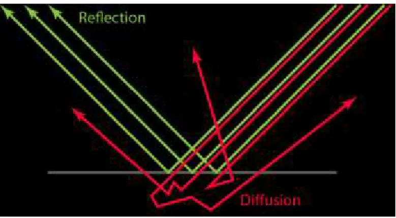
Fig. 4 - Light interaction
Specular reflection is light that is reflected when it hits a surface. Diffuse reflection is light that is refracted, scattered inside the medium, and refracted out again (see Fig. 4 – Light interaction). Diffuse materials are usually very absorbent. When light travels for too long inside them, it either is completely absorbed or it exits the object at approximately the same point it entered it, so the distance between the entry and exit point is usually neglected in the calculations – unless rendering materials with high scattering but low absorption using Subsurface Scattering, where that distance is taken into account (McDermott, Light and Matter: The Theory of Physically-Based Rendering and Shading, vol. 1, 2015, p. 4).
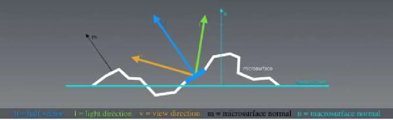
The orientation of the surface is defined by 3 elements: the shape of the mesh, on a larger scale; the normal map6 being applied to it, for large details; and the roughness or
glossiness map7, to represent microfacets8. Calculating the real surface direction at a
microscopic level for each light ray that hits it would need too much memory and computing power, so instead, the roughness map is used to describe a general measure of roughness instead of the actual microsurface details. Microsurface detail has a large effect on light behavior (see Fig. 5 – Light interacting with microsurface detail), and is a very important characteristic of PBR, since in the real world, there is a wide variety of microsurface features. An artist can paint variations of the microsurface roughness directly on the roughness/glossiness map, and PBR will display the change in reflection shape and its relative intensity. Since the reflectivity and microsurface detail values are physically related, it is an advantage for physically accurate rendering that the artist does not have independent control of each value. Marmoset founder and engineer Jeff Russell (2015, para. 36) also states on his article about PBR basic theory that
“Microsurface properties have other subtle effects on reflection as well. For example, the ‘edges-are-brighter’ Fresnel effect diminishes somewhat with rougher surfaces (the chaotic
6 Color image used to control the direction of each vertex’s normal vector in a 3D model (Polycount,
2016)
7 Vd. chapter 3.6.1 – PBR Workflow for more information on each map type and usage 8 microscopic details on a model’s surface
16
nature of a rough surface ‘scatters’ the Fresnel effect, preventing the viewer from being able to clearly resolve it).”
Fig. 5 - Light interacting with microsurface detail
The color of an object is defined by the light wavelengths that are reflected by the surface. The remaining wavelengths are absorbed by the object. The specular highlights on dielectric (not electrically conductive) materials is almost independent of wavelength, so it is usually the same color of the light source (McDermott, Light and Matter: The Theory of Physically-Based Rendering and Shading, vol. 1, 2015, p. 6).
Reflection and diffusion are mutually exclusive – if a light ray is reflected, it does not penetrate the surface, so it cannot be diffused. This means that a material with high reflectivity will show little to no diffuse light, while materials with high diffusion cannot be very reflective. This happens because of the Energy Conservation principle, which states that the intensity of the light leaving a surface must never be higher than that of the light received by that surface. When using PBR, the Energy Conservation principle is always enforced by the shader, which is an advantage for the artists working with it – “(…) [Energy Conservation] allows the artist
to work with reflectivity and albedo values for a material without accidentally violating the laws of physics” (Russell, 2015, para. 11).
A BRDF (Bidirectional Reflectance Distribution Function) is a function that defines the reflectance properties of a surface. For it to be physically plausible, it needs to use the Energy Conservation principle. (McDermott, Light and Matter: The Theory of Physically-Based Rendering and Shading, vol. 1, 2015, pp. 6-7).
The Fresnel effect states that light that lands on a surface at a grazing angle will show more reflectivity, which will make an object appear to have brighter reflections near the edges. For all smooth materials, reflectivity becomes gradually closer to 100% as the surface angle approaches 90º from the subject’s point of view, or as defined by Augustin-Jean Fresnel, the french physicist after whom the effect was named, “(…) the amount of light you see reflected
from a surface depends on the viewing angle at which you perceive it.” (McDermott, 2015, p.
7).
PBR reduces the artist’s control over the Fresnel effect, to create physically accurate representations. It uses material properties such as gloss and base reflectivity to automatically calculate the reflectivity of the material at a given angle (Russell, 2015, paras. 21-23).
PBR materials can be roughly divided into two categories: metals and non-metals (with exceptions). Dielectric materials need an albedo (diffuse) and specular map. The color from metals comes from the reflected light so they do not need a diffuse color, but they need an RGB specular map. Painted metal or rusted parts of metals are treated as a dielectric material. It is
17
important to add that in PBR, every color-related calculation is made in Linear Space, with the gamma value set to 1.0, so that light mimics its real-world behavior. To be displayed on a screen, the image must be in Gamma-encoded Space (sRGB) (McDermott, Light and Matter: The Theory of Physically-Based Rendering and Shading, vol. 1, 2015, p. 11). Electrically conductive materials will often exhibit reflectivities as high as 60-90%, where insulator (dielectric) materials usually have very low reflectivity, in the 0-20% range. Russell (2015, para. 16) adds that “It is this duality between metals and just about everything else that leads
some rendering systems to adopt ‘metalness’ as a direct input. In such systems artists specify the degree to which a material behaves as a metal, rather than specifying only the albedo & reflectivity explicitly”.
2.4. 3D Animated Film Production Technologies
With the evolution and increased accessibility of 3D animated film production technologies and tools, more people can experiment and learn how to create and use 3D assets for films and game development. With increasingly more capable and user friendly software and hardware, more quality indie games and short films are being produced, allowing for smaller teams such as in the short film Adam (2016)9 to create projects with a quality level that
rivals big animated film production companies.
“These days, children as young as five are playing with [3D Art] and older people who could barely draw stick figures can bring to life the beauty that has been in their imagination. Solo artists have already been able to create short animations on their own. Perhaps in the near future, individuals may be able to make entire movies all by themselves.” (Chopine, 2011,
p. 12)
2.4.1. Modelling and Sculpting
Modelling and sculpting are the most common methods used to create 3D assets for animation films. Modelling allows for more control over the individual elements of the 3D mesh, where the artist is able to control each vertex individually when needed. Sculpting gives the artist more freedom to express himself, by mimicking the tools used in physical sculpting to a virtual environment, where the artist can often disregard technical modelling details like geometry, topology and resolution.
Polygon modelling is the most widely used approach in animation and video game industries. A polygon is a virtual element defined by a minimum of three vertices connected by edges (a triangle). Polygon meshes render quickly and are supported by most 3D software packages, which means they can easily be imported and exported between them (Cantor & Valencia, 2004, p. 259).
“One potential disadvantage of polygon models is that they have a tendency to look faceted, so to create curved and smooth surfaces you need to increase the surface’s resolution by using a large number of vertices” (Cantor & Valencia, 2004, p. 259).
Box modelling is the most common polygonal modelling technique, where the artist starts with a low-resolution primitive geometry object (often a cube), that they will modify by moving its components until they get the desired result. Depending on the situation, the final
9 Vd. chapter 2.5.2 – Adam (2016) – Unity Technologies for more information on the production of this
18
result may or may not be subdivided to smooth the hard edges (Slick, 7 Common Modeling Techniques for Film and Games, 2016, paras. 6-8).
Edge modelling is also a polygonal modelling technique, often used to create complex models that require a specific topology and edge flow, as it happens when modelling a character’s face (see Fig. 6 – Facial edge flow in 3D modelling). This is accomplished by using polygons to create outlines of each prominent part of the object, and then filling the gaps between them (Slick, 7 Common Modeling Techniques for Film and Games, 2016, paras. 9-10).
Fig. 6 - Facial edge flow in 3D modelling
NURBS modelling is used for automotive and industrial modelling. NURBS models are not polygon based. They are created by automatically generating geometry connecting two or more Bezier curves (splines), which creates smooth surfaces, and instead of faces, edges and vertices, the geometry is controlled by moving the splines’ handles (Slick, 7 Common Modeling Techniques for Film and Games, 2016, paras. 11-12).
Digital sculpting is a technique that gives the sculptor artistic freedom by allowing them to ignore modelling constraints such as topology and edge flow and use real-world sculpting techniques in a digital environment. It is often done with a graphics pen tablet where the artist can interact with virtual chunks of clay and create high resolution meshes (often with millions of polygons) which allow for the creation of very small surface details (Slick, 7 Common Modeling Techniques for Film and Games, 2016, paras. 13-14).
Procedural modelling uses mathematical algorithms to generate models. It is often used to generate organic models such as trees or foliage, or complex environments such as cities or landscapes, where there can be a great variation that would be too time consuming to create by hand. Some examples of software that use this technique are Vue, Bryce, Terragen, SpeedTree and CityEngine (Slick, 7 Common Modeling Techniques for Film and Games, 2016, paras. 15-17).
Image Based modelling generates 3D models from a set of two-dimensional images. This technique has been used in movies such as The Matrix where time or budget restrictions
19
do not allow for the manual creation of a full 3D model (Slick, 7 Common Modeling Techniques for Film and Games, 2016, paras. 15-16).
3D Scanning, as the name implies, uses 3D scanner technology to generate an accurate mesh from a real-world object. For this technique to be used, a real object must exist before the model is created, which applies only to specific situations (Slick, 7 Common Modeling Techniques for Film and Games, 2016, paras. 17-18).
Most of the modelling packages used in the industry are equally capable, with some being arguably better than others in specific tasks. Each artist should experiment with as many applications as they can in order to find which is better for their needs or which they like working with the most.
One of the most important software aspects for aspiring animation filmmakers is the cost of the software. Short film filmmakers often have a low budget to buy software, rent a studio, equipment and hire a crew, and everything else that is needed in a short film production. Buying expensive software can often be impossible, so many studios opt in using free software or inexpensive indie versions when they are available (Manasseh & Ephraim Studios, 2014, para. 1).
Autodesk Maya and 3ds Max have been the industry standard modelling and animation software for many years. Maya is arguably the best of the two for animation, while 3ds Max is often considered better for modelling and asset creation for game development (Fronczak, 2011, para. 5-6). 3ds Max has been used in video games such as the Grand Theft Auto series, and Maya was used in multiple films such as the Spider-Man and Lord of the Rings series, and is often used in animation films (Smit, 2012, paras. 5-9).
Blender is a free to use commercially, all-in-one package, capable of most of the features offered by the main paid software, and has a large online community with many free courses and tutorials available (Fronczak, 2011, para. 4). It has been used in movies, commercials and games, including some open projects created by the Blender Foundation such as Big Buck
Bunny (2008) and the game Yo Frankie (2008) (Smit, 2012, paras. 12-14).“Their site [Blender] is also full of resources for beginners and experts and the community is warm and friendly with a lot of great insight and tips.” (Smit, 2012, para. 12).
2.4.2. Rigging
“Rigging is the process of setting up a controllable skeleton for the character that is intended for animation.” (Chang, n.d., para. 50)
For a 3D model to be animated, unless it is a simple animation that does not require deformation on the mesh, it needs to be rigged.
20
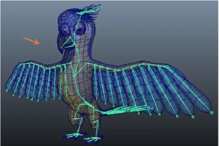
Fig. 7 - Character rig in Autodesk Maya
Rigging is the process of creating an (usually) internal virtual skeleton composed of joint deformers (see Fig. 7 – Character rig in Autodesk Maya) that will then be animated and will cause the model geometry to deform. These joint deformers work similarly in most 3D applications (Chopine, 2011, p. 87). Without a rig, the 3D model can be animated by translating, rotating or scaling it, but the mesh will always be stuck in the same pose it was created in (Pluralsight, 2014, para. 1).
“Joints are the points of articulation you create to control the model.” (Pluralsight,
2014, para. 2).
A model’s rig is a system of joints, bones and control handles following a parent-child hierarchy, which allows the animators to pose and animate the model (Slick, What is Rigging?, 2016, paras. 2-9). Joints in a humanoid 3D model are positioned roughly on the same places our skeleton’s joints are. Generally, the joints will be positioned on a point where the model will rotate or bend, such as an elbow or shoulder (Pluralsight, 2014, para. 2).
After the rig is completed, it is bound to the 3D mesh by a process named skinning (Slick, What is Rigging?, 2016, paras. 2-9). Without skinning, the mesh will not be affected by the joints movements. After skinning, the relationship between joints and mesh is often not ideal, so the rigger uses weight painting, which is a technique that sets the influence (weight) each joint will have on each of the mesh’s vertexes’ movement (Pluralsight, 2014, paras. 9-10). There are two main techniques used by a rig that define the way the joints’ hierarchy will affect the rig’s movement: Forward Kinematics (FK) and Inverse Kinematics (IK).
FK gives more control over the joints hierarchy, but since each joint needs to be positioned independently, it is not ideal in some situations where IK would be more efficient (Pluralsight, 2014, para. 6). In FK, rotating a joint in the rig will also affect all the joints that are below it in the joint’s hierarchy. As an example, in a humanoid rig, when the shoulder joint is rotated, the whole arm – elbow, wrist, hand, etc. – will rotate with it. When using this technique, the animator should follow the hierarchy and move the joints that are higher in the hierarchy first, in this case, start with the shoulder, then elbow, then wrist, and so on (Slick, What is Rigging?, 2016, paras. 10-11).
21
When using IK, the process is reversed: the last joint in the hierarchy of the IK section is the one that dictates the position of the joints above it. This means, using the same example as above, that the animator will position the wrist of the character in the desired place, and the position and rotation of the elements above it (elbow and shoulder) will automatically be calculated by the rig. This technique is often used when the final joint of the hierarchy needs to be placed precisely at one specific location (Slick, What is Rigging?, 2016, paras. 12-14).
“[Inverse Kinematics] allows the animator to animate independently of the chain’s hierarchy. Because of this IK is great when needing to have a character's arm stay planted on something.” (Pluralsight, 2014, para. 5)
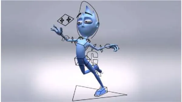
When rigging, most of the rig’s joints are positioned inside the mesh. Controlling the joints directly would be inefficient and cumbersome for an animator, so the rigger creates control curves, which are visual elements, usually positioned outside the mesh around the controllable joins (see Fig. 8 – Rig control curves), so that the animator can easily select and manipulate them (Pluralsight, 2014, para. 7).
Fig. 8 - Rig control curves
Joint Constraints are limits that can be imposed to an object’s position, rotation or scale. As an example, using a parenting constraint on two objects, makes the child object always follow the transformations applied to its parent (Pluralsight, 2014, para. 8). Constraints can be used to restrict the rig’s movements, in order to prevent unrealistic animations such as the elbow bending backwards or the head tilting or rotating too much, or to prevent or control the use of techniques such as squash and stretch, which can deform the mesh in unrealistic ways when exaggerated – although that may be desired, depending on the artistic style of the animation (Slick, What is Rigging?, 2016, paras. 15-17).
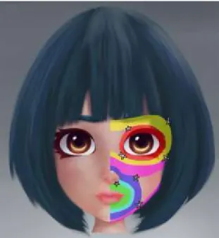
The facial rig for a character is usually separated from the rest of the body’s rig. Facial rigs often use a mixture of joints/bones and blend shapes that directly deform the mesh (Slick, What is Rigging?, 2016, para. 18). When using blend shapes, the artist modifies the mesh
22
directly and saves multiple poses that he will later be able to control using sliders (Pluralsight, 2014, para. 4).
2.4.3. Animation
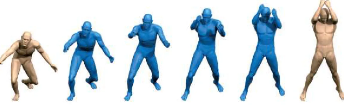
In 3D, animation consists of varying the properties of an object through time, such as position, rotation, shape and surface style, in a three-dimensional space (Rebelo, 2003, para. 1). Modern 3D software has the ability of keyframe interpolation (see Fig. 9 – Animation interpolation), which takes into account the transformations that happen to an object between one keyframe and the next one, and automatically creates the movement in between the two frames (Gray, 2015, para. 6).
Fig. 9 - Animation interpolation
Motion Capture (MoCap) can produce realistic results in animation. It uses cameras and specific suits with markers that have their position tracked by infrared cameras and translated into movement data that can be interpreted by the 3D software and mapped on to the character’s rig (Rebelo, 2003, para. 9). At first, MoCap was seldom used for animation due to the technology’s limitations, but is now used in many 3D animation scenarios, from video games to CG effects in movies (Gray, 2015, para. 7).
MoCap is a costly technology, to which not everyone has access to. It is also a technology that requires a lot of cleaning up after the capture process is finished to correct capture errors or make it more believable, particularly when the target character is not a humanoid character. Artists that don’t have access to a MoCap studio often learn how to incorporate this technique by importing MoCap data from online MoCap libraries (Gray, 2015, paras. 8-9).
“MoCap subjects, usually actors, are placed in a special suit containing sensors that record the motion of their limbs as they move. The data is then linked to the rig of a 3D character and translated into animation by the 3D software.” (Gray, 2015, para. 7).
One of the most important skills of an animator is the capacity to observe the world around them. Learning from film, theatre, comic books and other animators’ work is also important, and some animators also take acting lessons (Gray, 2015, paras. 10-11).
3D animators, while often not in charge of the character’s rigging, should have a good understanding of how rigs and FK and IK systems work. Animating is a craft that requires a lot of practice and attention to detail (Gray, 2015, paras. 13-14).
23
To create realistic animations or real-world behaviours in animation, tools like physics engines can also be used to apply physical laws (such as gravity) to an object to generate its movement (Rebelo, 2003, paras. 6-7).
2.4.4. Textures and Maps
A few years ago, the need for optimization was much higher than today. Textures had to be very small and with limited color palettes, geometry resolution had to be extremely low and even when using many optimization techniques, the results would not even approximate those we can achieve today.
Textures can be created by using image editing software such as Adobe Photoshop or 3D painting software such as Mudbox or ZBrush (Beane, 2012, p. 39).
Maps such as displacement, normal or bump maps can be used as an addition to the assets’ modelling by creating or simulating surface details that would be too time consuming to create using standard modelling tools (Cantor & Valencia, 2004, p. 264). Bump maps are grayscale maps that simulate height on a model’s surface, creating the appearance of depth in the direction of the camera. Normal maps are RGB color maps that simulate height on all three axes, affecting the angle of the geometry normals directly, giving more accurate results. Displacement maps are grayscale maps that affect the geometry directly, which gives the best results, but requires a high amount of processing (Chopine, 2011, pp. 159-160).
When creating maps for real time, their limitations are defined by the system specifications. For optimization, multiple techniques can be used, such as tiling textures so that the final result appears to be a single large map (Kerlow, 2004, p. 234).
Software such as The Foundry’s MARI, Maxon Bodypaint 3D, Pixologic ZBrush, Autodesk Mudbox, Pilgway 3D-Coat and Allegorithmic Substance Painter allow for the painting of textures directly in the 3D model (sandy, 2014).
Adobe Photoshop or Gimp are often used to paint or edit textures in a 2D space, directly over the exported UV Maps (sandy, 2014, p. 1, paras. 42-46). Photoshop’s versions CS6 and CC can now also import 3D asset files into the software and create new textures for it, which can be previewed directly on the 3D model as an UV overlay. The textures can then be edited or painted directly in the 3D model, or as a 2D image. They also allow for texture map reparameterization, which corrects distortion caused by poor UV mapping, creation of tiles for repeating textures, and for the selection of specific parts of the model to be painted or temporarily hidden for ease of use (Adobe Systems Incorporated, 2017).
Knald and xNormal are applications used to generate normal, ambient occlusion and displacement maps from high resolution meshes. Other applications such as Bitmap2Material allow for the generation of those maps from image files (sandy, 2014, p. 2, paras. 1-14).
UVLayout and Ultimate Unwrap 3D are UV Mapping applications, used when the standard UV Mapping functionalities of the main software aren’t enough (sandy, 2014, p. 2, paras. 15-23).
2.4.5. Lighting and Rendering
Aldric Chang, founding Managing Director of Mediafreaks defines lights in 3D as “(…)
24
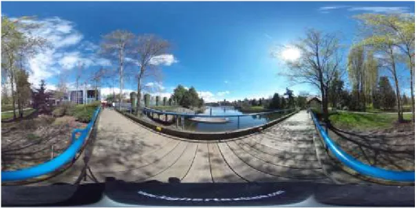
High Dynamic Range Images (HDRI) are spherical images that are often used as a sky dome where light is emitted from the image to illuminate the scene (see Fig. 10 – HDRI example). They allow for realistic renders and for incorporation with live action footage, to match the original video lighting (Chopine, 2011, p. 188).
Fig. 10 - HDRI example
“An HDRI contains not only color information, but also information about the luminosity or intensity of the light.” (Chopine, 2011, p. 188)
Light animation effects can be used to create or change the mood in a scene. Light produced by natural phenomena such as lightning or fire usually require animation to produce realistic results. These animations can either be created by animating the light’s parameters, using procedural animation, lighting “tricks” as used in traditional stage plays or movie special effects, or added in post-production (Kerlow, 2004, pp. 318-320).
“A wide variety of lighting effects that affect the mood of a scene can be created by animating the intensity of a light source as well as its color, cone angle, and fall-off.” (Kerlow,
2004, p. 317)
The rendering setup process varies from engine to engine. Most traditional rendering engines are able to render in passes (see Fig. 11 – Render passes), which is a process that breaks a render into individual pieces, such as color information, shadow information, highlight information or reflection information. By using this method, the compositing artist has more control over the final look of the scene, since each of these pieces can be individually edited and then merged together in the end (Beane, 2012, pp. 244-245).