Universidade de Aveiro Departamento deElectr´onica, Telecomunica¸c˜oes e Inform´atica, 2015
Jo˜
ao ´
Alvaro Couceiro
Cardoso
3D manipulation and navigation methods with
gestures for large displays
M´
etodos de manipula¸
c˜
ao e navega¸
c˜
ao com gestos
Universidade de Aveiro Departamento deElectr´onica, Telecomunica¸c˜oes e Inform´atica, 2015
Jo˜
ao ´
Alvaro Couceiro
Cardoso
3D manipulation and navigation methods with
gestures for large displays
M´
etodos de manipula¸
c˜
ao e navega¸
c˜
ao com gestos
para ecr˜
as p´
ublicos
Disserta¸c˜ao apresentada `a Universidade de Aveiro para cumprimento dos requisitos necess´arios `a obten¸c˜ao do grau de Mestre em Engenharia de Computadores e Telem´atica, realizada sob a orienta¸c˜ao cient´ıfica do Pro-fessor Doutor Paulo Miguel de Jesus Dias, ProPro-fessor Auxiliar, e da Profess-ora DoutProfess-ora Maria Beatriz Alves de Sousa Santos, ProfessProfess-ora Associada com Agrega¸c˜ao do Departamento de Electr´onica, Telecomunica¸c˜oes e In-form´atica da Universidade de Aveiro
o j´uri / the jury
presidente Professor Doutor Joaquim Jo˜ao Estrela Ribeiro Silvestre Madeira
Professor Auxiliar da Universidade de Aveiro
arguente principal Professor Doutor Jos´e Francisco Creissac Freitas Campos
Professor Auxiliar da Escola de Engenharia da Universidade do Minho
orientador Professor Doutor Paulo Miguel de Jesus Dias
agradecimentos / acknowledgements
Servem as seguintes palavras para expressar de uma forma simples, um agradecimento que nunca ser´a pago por palavras. Um agradecimento muito especial aos meus pais e o meu irm˜ao, que se sempre me ajudaram e acred-itaram em mim durante todas as fases da minha vida. `A minha av´o por toda a amizade e carinho durante toda a minha vida. Aos meus grandes amigos, Ruben Costa, Miguel Senos, Luis Silva e Lia Louren¸co por sempre me terem apoiado. Por ´ultimo, mas n˜ao menos importante, aos Professores Paulo Dias e Beatriz Sousa Santos pela orienta¸c˜ao desta disserta¸c˜ao.
Resumo O aumento da utiliza¸c˜ao de ecr˜as p´ublicos levou `a necessidade de desen-volver novas formas de intera¸c˜ao com este tipo de sistemas. A solu¸c˜ao que foi considerada nesta disserta¸c˜ao recorreu `a utiliza¸c˜ao de interfaces de utilizador baseadas em gestos, uma vez que n˜ao exigem que os utilizadores usem qualquer tipo de dispositivos para al´em do seu pr´oprio corpo.
Esta disserta¸c˜ao continua o trabalho realizado anteriormente no ˆambito do projecto DETI-Interact, que consiste num sistema interativo baseado num ecr˜a p´ublico instalado na entrada do Departamento de Electr´onica, Telecomunica¸c˜oes e Inform´atica, para o qual foram desenvolvidas v´arias ap-lica¸c˜oes que permitem intera¸c˜ao com conte´udos 2D e 3D atrav´es de um sensor Kinect.
O principal objetivo deste trabalho foi o de melhorar esses m´etodos com os novos gestos dispon´ıveis pela mais recente vers˜ao do Kinect SDK. Foram realizadas trˆes experiˆencias com utilizadores para avaliar a usabilidade os m´etodos de intera¸c˜ao propostos, proporcionando a oportunidade de mel-horar os m´etodos existentes, levando `a contribui¸c˜ao de um novo m´etodo para manipula¸c˜ao de objectos 3D.
Abstract The increasing usage public displays led to the necessity of new forms of interaction with this type of systems. The solution that was considered in this dissertation involved gesture-based interfaces, since they do not require users to carry or use any input device other than their own body.
This dissertation continues and extends previous work on DETI-Interact, an interactive public display system located at the lobby of Department of Electronics, Telecommunications and Informatics, to which several applica-tions have been developed allowing interacapplica-tions with 2D and 3D contents using a Kinect sensor. The main objective of this work was to improve those methods and develop new ones using the new gestures provided by the latest version of the Kinect SDK.
Three user studies were conducted to evaluate the usability of our pro-posed navigation and manipulation methods, leading to this dissertation main contribution of a novel method for the 3D object manipulation.
Contents
Contents i List of Figures v List of Tables ix 1 Introduction 1 1.1 Objectives . . . 21.2 Outline of this Document . . . 2
2 Related Work 3 2.1 Introduction . . . 3
2.2 DETI-Interact . . . 3
2.3 Interaction with Public Displays . . . 5
2.3.1 Content generation . . . 5
2.3.2 Call-of-attention . . . 6
2.4 Interaction with 3D environments . . . 8
2.4.1 3D Object Manipulation Methods . . . 9
2.4.2 3D Navigation Methods . . . 13
2.5 Conclusion . . . 15
3 Methods for 3D manipulation and navigation 17 3.1 Proposed Methods . . . 17
3.1.1 3D Object Manipulation . . . 17
3.1.2 3D Navigation . . . 19
3.2 Tools . . . 19
3.3 Implementation of the proposed methods . . . 21
3.3.1 OneHand . . . 21
3.3.2 Handle bar . . . 23
3.3.3 Improved Handle bar . . . 25
3.3.4 Handle bar with user representation . . . 27
3.3.4.1 Hands Avatars . . . 27 3.3.4.2 Full-Body Avatar . . . 28 3.3.5 3D Navigation . . . 30 3.3.5.1 BikeHandleBar . . . 31 3.3.5.2 SteeringWheel . . . 32 3.4 Conclusion . . . 33
4 Usability studies 35
4.1 Preliminary experiment with 3D Manipulation methods . . . 35
4.1.1 Experimental Protocol . . . 35
4.1.1.1 Tasks . . . 36
4.1.2 Results . . . 38
4.1.3 Conclusion . . . 40
4.2 Full Experiment with 3D Manipulation using Gestures - Improved ”HandleBar” 41 4.2.1 Participants . . . 41
4.2.2 Hypothesis and variables . . . 42
4.2.3 Tasks . . . 42
4.2.4 Performance measures and other collected data . . . 43
4.2.5 Experimental design . . . 43
4.2.6 Results . . . 43
4.2.7 Conclusion . . . 48
4.3 Third experiment with 3D Manipulation using Gestures – Avatars for the Hands 49 4.3.1 Participants . . . 49
4.3.2 Hypothesis and variables . . . 50
4.3.3 Tasks . . . 50
4.3.4 Performance measures and other collected data . . . 50
4.3.5 Experimental design . . . 50
4.3.6 Results . . . 50
4.3.7 Conclusion . . . 53
4.4 Navigation using Gestures . . . 54
4.4.1 Participants . . . 54
4.4.2 Hypothesis and variables . . . 56
4.4.3 Tasks . . . 56
4.4.4 Performance measures and other collected data . . . 57
4.4.5 Experimental Design . . . 57 4.4.6 Results . . . 57 4.4.7 Conclusion . . . 59 5 Conclusions 61 5.1 Future Work . . . 62 Bibliography 63 Appendices 67 A Code Base Structure 68 A.1 Project Setup . . . 68
A.2 WPF Structure . . . 69
A.2.1 MainWindow . . . 69
A.2.2 MainPage . . . 70
A.2.2.1 Code-Behind of the Main Page . . . 70
A.2.3 Creating a new Page . . . 71
A.3 Kinect controls . . . 72
A.3.2 Kinect User Viewer . . . 73 A.3.3 Kinect Tile Button . . . 73 A.3.4 Kinect Scroll Viewer . . . 73
B Questionnaires 75
B.1 Questionnaire from the accuracy test . . . 76 B.2 Questionnaire from the avatar usability test . . . 80 B.3 Questionnaire from the navigation test . . . 83
List of Figures
2.1 DETI-Interact public display, [Dias et al., 2014]. . . 4 2.2 Digifieds public display, [Alt et al., 2011]. . . 6 2.3 LookingGlass public display - field-study and the three user representations:
No Representation, Silhouette, and Image, [M¨uller et al., 2012]. . . 7 2.4 ChainedDisplays public display - three configurations allow different social
ex-periences by the same system, [Koppel and Walter, 2012]. . . 8 2.5 Handle bar metaphor for virtual object manipulation with a set of recognizable
hand gestures, [Song et al., 2012]. . . 9 2.6 Example of use of the rotation and the list of speech commands in Fusion4D
[Matsumura and Sonnino, 2011]. . . 11 2.7 Multi-hand gestures interaction system for architectural design developed by
[Shiratuddin and Wong, 2011]. . . 11 2.8 Gestures and voice recognizable on the system developed, [Lee et al., 2013]. . 12 2.9 Gesture navigation in the educational application Molecule Viewer, [Lee et al., 2013] 12 2.10 Top Left: The freehand 3D selection technique, Top Right: an example of 3D
interface, Bottom: the workflow of the method, [Ren and O’Neill, 2013]. . . . 13 2.11 Using a flying broomstick as the metaphor for a gesture based navigation
through 3D environments, [Ren et al., 2013] . . . 14 2.12 Right: Camera manipulation using user’s gestures. Left: Set of recognizable
gestures for camera manipulation, [Kim et al., 2012]. . . 15 3.1 The two new methods for 3D object manipulation. . . 18 3.2 NeoAxis 3D Engine - Examples of two applications and the Map and Resource
editors.1 . . . 20 3.3 The two coordinate system used in this dissertation. (a) Kinect coordinate
system. (b) NeoAxis 3D engine coordinate system. . . 21 3.4 Diagram of the ”OneHand” method. . . 21 3.5 Diagram of the ”HandleBar” method. (a) Top view, rotate around Z axis. (b)
Front view, rotate around X axis. (c) Scale manipulation. . . 23 3.6 Skeleton model used by the Kinect SDK ([Microsoft, 2013b]). . . 24 3.7 Diagram of the improved HandleBar method. . . 26 3.8 Animated 3D model of the hand used in the ”HandleBar” method with user
representation. . . 27 3.9 Animations states (grab and idle) and the transitions between both states. . . 27 3.10 Avatars of the hands in the ”HandleBar” method with user representation. . 28
3.11 Correlation between the skeleton of the fully rigged 3D model of a human
character and the skeleton obtained from the Kinect SDK2. . . 29
3.12 Examples of cases in the Kinect skeleton, in which some joints have its local axis system swapped. . . 30
3.13 Diagram of the ”BikeHandleBar” navigation method. . . 32
3.14 Diagram of the ”SteeringWheel” navigation method. . . 32
4.1 3D Manipulation - Rotation accuracy test. . . 36
4.2 3D Manipulation - Rotation and scale accuracy test. With the ”OneHand” method the GUI buttons for scale are visible. . . 37
4.3 Rotation accuracy and Rotation with Scale tests - Questionnaire results. . . . 38
4.4 Rotation accuracy test - Angular Distance and Time. . . 39
4.5 The second experiment: observer and participants work flow, interaction meth-ods and data collected during the experiment. . . 41
4.6 Second experiment rotation accuracy test - Questionnaire results. . . 44
4.7 Second experiment rotation accuracy test - angular distance (left) and time (right). . . 44
4.8 Second experiment rotation accuracy test - first time at 5 degrees. . . 45
4.9 Second experiment rotation with scale accuracy test - Questionnaire results. . 46
4.10 Second experiment rotation with scale accuracy test - angular distance (left) and time (right). . . 46
4.11 Second experiment rotation accuracy test - Scale. . . 47
4.12 Second experiment rotation accuracy test - first time at 5 degrees. . . 47
4.13 The third experiment: observer and participants work flow, interaction meth-ods and data collected during the experiment. . . 49
4.14 Third experiment avatar usability test - Questionnaire results. . . 51
4.15 Third experiment avatar usability test - Angular distance. . . 51
4.16 Third experiment avatar usability test - Time. . . 52
4.17 Third experiment avatar usability test - First time at 5 degrees. . . 52
4.18 Third experiment avatar usability test - User preference. . . 53
4.19 The navigation experiment: observer and participants work flow, navigation methods and data collected during the experiment. . . 54
4.20 Navigation Test - Navigation Methods . . . 55
4.21 The maze used during the experiment regarding the navigation methods. . . 56
4.22 Navigation test - Questionnaire results. . . 57
4.23 Box plot of navigation test results - distance travelled and time spent. . . 58
4.24 Navigation test - Collisions. . . 58
4.25 Navigation test - User Preference. . . 59
A.1 Reference Manager . . . 68
A.2 Main Window structure (eXtensible Application Markup Language (XAML)). 69 A.3 Code-behind of Main Window. . . 69
A.4 Main Page of the new version of DETIInteract. . . 70
A.5 Main Page (XAML) . . . 70
A.6 Sensor Binding. . . 71
A.7 New page structure (XAML) . . . 72
A.9 Kinect Region. . . 72
A.10 Kinect User Viewer. . . 73
A.11 Kinect Tile Button . . . 73
List of Tables
3.1 Color scheme of the handle bar indicating which gesture was detected. . . 26 4.1 Rotation accuracy test - Average and median of the results obtained. . . 39 4.2 Rotation with Scale accuracy test - Average and median of the results obtained. 40 4.3 Second experiment rotation accuracy test - Average and median of the
per-formance measures obtained. . . 45 4.4 Second experiment rotation with scale accuracy test - Average and median of
the performance measures obtained. . . 48 4.5 Third experiment avatar usability test - Average and median of the
perform-ance measures obtained. . . 53 4.6 Navigation Test - Average and median of the results obtained. . . 59
List of Acronyms
API Application Programming Interface DOF Degree of Freedom
DETI Department of Electronics, Telecommunications and Informatics FT5 First time at 5 Degrees
GBI Gesture-based Interaction GUI Graphical User Interface
IEETA Instituto de Engenharia Electr´onica e Telem´atica de Aveiro IDE Integrated Development Environment
MHG Multi-Hand Gesture PBI Pointer-based Interaction SDK Software Development Kit UI User Interface
WPF Windows Presentation Foundation
Chapter 1
Introduction
The widespread use of public displays raised significant research on how users can interact with such systems without cumbersome input devices that are unsuitable for this type of installations.
The recent developments in low-cost tracking systems, such as Leap Motion and Microsoft Kinect and gesture recognition algorithms led to the increasing popularity of gesture-based interfaces [Garber, 2013]. This type of interface makes use of the identification of body movements, so systems may determine which specific command a particular gesture represents and take the appropriate action. On the other hand, gestural interfaces seem to be the best solution for the interaction with public displays since they do not rely on the usage of any controller.
This dissertation continues previous work in the scope of the DETI-Interact project [Duarte, 2011], [Cardoso et al., 2012], [Sousa, 2013], [Cardoso, 2013a], which consists of a public display based system controlled through gestures using a depth sensor. Throughout various projects, some content for this public display has already been developed, although the common approach was 2D based content.
There has been recently an increasing interest on visualize and manipulate information and other 3D content, which led us to consider that it would be a good opportunity to enable 3D content on our public display. This would allow passing by users to manipulate 3D models, navigate through virtual environments or simply have fun with 3D games, which could make the users’ interactive experience much more appealing, bringing more users to DETI-Interact. After the integration of a 3D engine that could support the 3D development within the current version of DETI-Interact, we were able to identify the type of 3D content to be implemented, which implied research on suitable methods for the manipulation of 3D objects and navigation in 3D virtual environments.
1.1
Objectives
The general objective of this work is to integrate 3D content into the public display in the lobby of our department that provides information to students (DETI-Interact). We consider that 3D content in this context should consist of applications that enable the visualization of 3D models or to perform a virtual tour of the campus.
In order to perform such integration an evaluation of how gesture based interfaces could handle the complex interactions for 3D interaction was needed. Thus, our goal is to propose two methods for the manipulation of 3D objects and two methods for navigation in 3D environments using gestures.
1.2
Outline of this Document
The remainder of this document is structured in the following way:
Chapter 2 – Related Work – presents the work related to public displays and gesture-based interaction with 3D environments . We describe several existing public display systems while analysing the problems of developing such systems. We also describe several approaches for gesture-based interaction, specifically for the manipulation and navigation tasks.
Chapter 3 – Methods for 3D manipulation and navigation – proposes the interaction methods for the manipulation of 3D objects and navigation in virtual environments, describing the main concepts, algorithms and implementation.
Chapter 4 – Usability studies – presents the evaluation process of the developed methods during the user study. Describes the tests executed, the implementation and presents the results.
Chapter 5 – Conclusions – presents some concluding remarks and points to further research opportunities.
Chapter 2
Related Work
2.1
Introduction
The objective of this chapter is to give an overview of the current state of the art, analyzing the previous work in relevant areas for this dissertation. This analysis will be divided in two main subjects: interaction with public displays, and interaction with 3D environments using gestures.
Firstly we are going to briefly describe the topic of public displays, since our dissertation is inserted in a project that involves a public display. Within this topic we are going to review similar projects, and the problems that arise with this type of systems.
Since our main objective is to develop and integrate novel ways of interaction with virtual environments, we present a review of the state-of-the-art of gesture-based methods for both 3D object manipulation and navigation.
2.2
DETI-Interact
This dissertation continues previous work on a system including a public display [Duarte, 2011], [Cardoso et al., 2012], [Sousa, 2013], [Cardoso, 2013a]. DETI-Interact is a system that presents information to students on a large display at the lobby of the Univer-sity of Aveiro’s Department of Electronics, Telecommunications and Informatics (DETI) (see Figure 2.1).
DETI-Interact is evolving to its third iteration, being a result of six years of development and contributions from alumni [Dias et al., 2014]. The project started in 2009 with an initial approach using an Android smartphone to interact with the system. This first version of DETI-Interact required an initial configuration in order to perform the pairing between the two devices. This led users to show little interest in the system. To overcome this issue DETI-Interact was redesigned, enabling gesture interaction using a Kinect sensor.
As first approach, two types of interaction were developed [Cardoso, 2013a]: Gesture-based Interaction (GBI) and Pointer-Gesture-based Interaction (PBI). The interaction using GBI consisted of using one hand to perform the gestures: Swipe, Push, Pull and Timed stay. The PBI consisted of controlling the cursor by moving one hand and selecting interface items by pushing with the other hand.
In the academic year of 2012–2013, the layout of DETI-Interact was redesigned to better accommodate the introduction of gesture interaction. Due to some problems detected with
Figure 2.1: DETI-Interact public display, [Dias et al., 2014].
the gesture-based methods implemented previously, the interaction was substituted by hover buttons, where users could place their hand over the button and wait for a timer. This version also introduced a call-of-attention module to capture users’ attention when they pass in front of the display.
One of the main goals of DETI-Interact is to be used as an information display for students and visitors, however, it has become a platform of development of several satellite projects (e.g. final project of Human–Computer Interaction course) [Dias et al., 2014].
2.3
Interaction with Public Displays
Large public displays with different purposes and interaction capabilities are becoming more dominant on our technological landscape. In this section we will do a survey of existing systems, in order to analyse the problems inherent to such applications, particularly types of interaction and content for interaction.
Several projects of continuous development on public displays are presented by ([Friday et al., 2012]) at the Lancaster University, UK. This study describes the authors’ 16 years of experiences with public displays systems, focusing on content creation and con-trol, programmable infrastructures, and applications. Several systems were developed on the context of this study, although some problems inherent to public displays were found, from which we highlight the applications to be implemented and their acceptance by the users, as well the user generated content. In their short survey, [Hinrichs et al., 2013] state that the diversity of these systems and the context in which they are inserted present different requirements regarding interface design and interaction techniques. They also analyse how these technologies could evolve into methods that could change entertainment and information seeking in public spaces, making passive observers into actors.
Motivated by the shortage of generally accepted design guidelines, [Alt et al., 2012] con-ducted a study on how to evaluate public displays systems. Based on a literature survey and on their own experiences, they provide a set of guidelines to be applied when evaluating public displays, in which they considered metrics such as audience behaviour, user experience, user acceptance, user performance, display effectiveness, privacy and social impact. From the presented guidelines we highlight the consideration of the impact of the content and the un-derstanding of the users, who are the main target for these installations. One of the common problems with public displays is the fact that they do not receive a lot of attention.
This happens as passers-by do not expect the interactivity of the display nor they expect to find interesting content. Since creating customized content that reflects the users’ interests is expensive, the solution that is mentioned is the self-generated content.
During our research one of the first issues identified was finding content for interaction, and how to bring users to create content for interaction, as the relevance of the different content to present on public displays is what brings users to interact with this type of systems. 2.3.1 Content generation
[Alt et al., 2011] considered that a public display system could be implemented in order to exhibit the information (classified ads) commonly present at the public notice areas. This led to the development of the Digifieds system allowing users to create, publish, and retrieve classified ads using a public touch-screen display, a mobile application or a web application. This solves the problem of creating content, since the users are the active part on creating it. Although they explored a rather specific application (public notice areas), they concluded that people were interested in public displays as communication medium.
Considering the user-generated content approach, this solution could not be implemented on DETI-Interact, since it is a touch-less gesture based system it becomes difficult for users to create and display their own content. Another problem of user-generated content arises from the fact that a moderator would be needed to filter the content to be displayed.
Figure 2.2: Digifieds public display, [Alt et al., 2011].
[Cardoso, 2013b] contributes with two main subjects concerning public displays: under-standing how users behave and interact with public displays, describing the information that can explicitly or implicitly be gathered from interactions, introducing the concept of digital footprints, and also providing a toolkit – PureWidgets, that provides a software abstraction, supporting various kinds of interaction mechanisms.
The digital footprints concept can be considered as a taxonomy of information generated during the interaction and derives from the public display analysis in the point of view of the information collected during the interaction and how it could be mapped to content adaptation procedures. This information is structured in a conceptual map that establishes the adaptation strategies and the interaction mechanisms (e.g. presence sensing, self-exposure, user-generated content, and actionables).
The PuReWidgets toolkit approaches the content creation problem inherent in public dis-plays systems. The author states that programmers could use this toolkit in order to easily implement interaction features in their web-based applications for public displays. PuReWid-gets is said to provide high-level abstractions of the interaction mechanisms in a form of wid-gets. There are various types of widgets that implement the several interaction mechanisms derived from the digital footprints.
2.3.2 Call-of-attention
Analysing the previous iterations of DETI-Interact, we realized that the application was hardly used by students. Besides the problem mentioned above regarding content, we believed that this was due to a problem mentioned in research papers named call-of-attention. This means that often public displays have difficulties to manifest their interactivity to passers-by. [M¨uller et al., 2012] approached this topic by conducting a field study on how passers-by notice the interactivity of public displays (Figure 2.3). In their paper these authors have focused on the representation of the user as a cue to interactivity, by conducting experiments under these conditions: an interactive colored image of the user (mirror image), a white filled silhouette of the user and a 2D avatar.
The conclusions were that using a mirror image turns out to be the more effective way of communicating that the display is interactive, since it caused passers-by to inadvertently interact with it. Another interesting conclusion was that mirror images are more effective than
silhouettes and avatars, and even more effective than traditional call-to-action modules (e.g. ”Touch to start” label). They also remarked that passers-by noticed late the interactivity of the public display (landing effect ), which means that often they have to walk back to interact. These findings could be useful as guidelines to increase the effectiveness on calling more users to interact with public displays.
Figure 2.3: LookingGlass public display - field-study and the three user representations: No Representation, Silhouette, and Image, [M¨uller et al., 2012].
[Koppel and Walter, 2012] presented another approach to the topic of calling-of-attention called Chained Displays, thus introducing a combination of several screens to create an altern-ative to the traditional flat public displays. In other words, these screens are combined into a large non-flat continuous display surface. These authors conducted a field study to com-pare three chained display configurations: Flat, Hexagonal and Concave (Figure 2.4). They examined how the angularity between the displays impacted the behavior from the person interacting (actor), the people watching the interaction (audience) and people just passing by.
The main conclusions were that the Flat configuration created the highest honeypot ef-fect, which consists of the social effect of people being attracted to the public display by other people standing close to it [Brignull and Rogers, 2003]. This configuration also caused individuals to position at the extremities of the display, groups to divide and occupy multiple screens, and fostered social learning. The Hexagonal configuration permitted up to six users to interact independently on adjacent screens. The Concave configuration limited the num-ber of simultaneously interacting people, and caused groups to split into actors and audience. These results present another way to trigger different user behaviour, and could be considered in order to change how users react to the presence of public displays.
Figure 2.4: ChainedDisplays public display - three configurations allow different social exper-iences by the same system, [Koppel and Walter, 2012].
2.4
Interaction with 3D environments
Currently, mid-air interaction supported by gestural inputs has received increasing atten-tion from both research community and gaming industry. [Bowman, 2014] points 3D user interfaces (UI) as the natural choice for large display contexts. [Bowman et al., 2004] stated that traditional mouse and keyboard are difficult to use because public displays are meant to call to interaction multiple users. Also, users want some liberty of movement in front of the display. Touch screens can solve some of these problems, but not without imposing another set of limitations, e.g. the user must stand at arm’s reach from the display, limiting the amount of the display that can be seen.
The implementation of 3D user interfaces is presented as the optimal solution, in which the usage of a tracked handheld device, the bare hands, or the whole body as the means of input allows the interaction from any location, while enabling multiple users.
The definition of 3D user interface is presented by [Bowman et al., 2004], and consists of ”a User-Interface (UI) that involves a human-computer interaction in which the user’s tasks are performed directly in a 3D spatial context, that can be either physical or virtual, or both”. In their state-of-art review [Jankowski and Hachet, 2014] defined that interactive 3D en-vironments are ”computer generated representations of real-world spaces through which users can navigate and/or in which they can interact with objects in real time”. In their previous work, they mentioned that there are three universal interaction tasks commonly used through-out the literature: Navigation – the process of moving around in a virtual environment; Se-lection and Manipulation – techniques or methods of choosing an object and performing the translation, rotation and scale operations; System Control - the communication between user and the system which is not part of the virtual environment.
In the scope of this dissertation we will only address the manipulation and navigation tasks, since our work is based in applications that only consider the visualization of 3D models and the navigation in virtual environments.
[Parracho, 2013] developed several methods for both manipulation and navigation. “But-ton Mode” and “Mixed Mode” as manipulation methods for handling 3D virtual objects, where a combination of buttons and gestures provided the rotation and scaling operations.
For navigation methods, “BikeMode” and “Free Hand Mode” were developed. “BikeMode” used both hands acting as grabbing a bicycle handler and as the user advances one and re-tracts the other, the view camera will rotate accordingly. “Free Hand Mode” was implemented based on the users propensity to use their dominant hand to control a mouse on a computer system. Thus, this method used it as an advantage, controlling the view camera with only one hand.
This section presents current studies on other methods for both object manipulation in a 3D and gesture navigation in 3D virtual environments.
2.4.1 3D Object Manipulation Methods
The manipulation of 3D objects using gestures is being studied for a long time, as [Bowman and Hodges, 1997] mention this capability as a desirable feature in many VR ap-plications and is typically accomplished using a real-world metaphor.
We start by presenting the work that strongly contributed to the development of our manipulation and navigation methods. [Song et al., 2012] proposed a handle bar metaphor as an effective control between the user’s hand gestures and the corresponding virtual object manipulation operations.
The main strength of this metaphor is the physical familiarity that is presented to the users, as they mentally map their bi-manual hand gestures to manipulation operations such as translation and rotation in a 3D virtual environment. One of the features that proved to be effective was the visual representation of a virtual handle bar corresponding to the ever-changing positions of the user’s hands (Figure 2.5), since it provided a strong sense of control to the user during the interactive visual manipulation.
Figure 2.5: Handle bar metaphor for virtual object manipulation with a set of recognizable hand gestures, [Song et al., 2012].
Their handle bar interaction design offered the 7 degrees of freedom (Degree of Freedom (DOF)) for the manipulation (3 translations, 3 rotations, and 1 scaling), allowing users to change smoothly between these operations.
The system can recognize three basic hand gestures, namely point, open, and close. The point gesture is associated with the handle bar and close is linked to the virtual object. Using the bi-manual gestures will perform basic rotation-translation-scaling manipulation of the handle bar or object, depending on whether point or close gestures are used.
The selected object can be translated in the x, y, and z directions by translating while both hands are with the closed fist gesture activated. The translation of the object is based on the movement of the virtual handle bar mid-point, determined between the two closed fists.
The object rotation about a specific axis is implemented based on the relative angular displacement of the virtual handle bar. Since the wrist-based rotation could not be detected by the depth sensor, the rotations about the x-axis cannot be directly activated using the handle bar. Though, the rotation about the x-axis was obtained by the recognition of the ”pedalling” motion of both hands, which consisted of the bi-manual unidirectional rotation about the x axis. The authors also implemented a constrained rotation variation using a combination of the point and open gestures in each hand to start this manipulation. The handle bar is changed to a ”cranking bar” with a perpendicular extension, and by closing both fists the user enters the constrained rotation state. (see Figure 2.5)
The scaling operation is done by moving the two closed hands towards each other (scale down) or away from each other (scale up).
In their experiments, the authors also have employed this new method on a virtual mo-lecule exploration application, where they have manipulated a virtual camera, concluding that this method could be used as an intuitive and flexible way of performing interactive visual navigation in a 3D virtual environment.
The lack of suitable activation methods led some authors to use a combination of ges-tures and voice recognition to switch between manipulations. [Matsumura and Sonnino, 2011] present Fusion4D, which is an example of such interface for manipulating 3D objects. The interface allows a user to move, rotate, and scale objects directly in a 3D virtual space using hand gestures and speech commands (Figure 2.6). Besides enabling interaction with gestures, Fusion4D also takes advantage of the use of stereoscopy adding a sense of depth when viewing objects. Its initial function was to assist the VIDA project for the Interactive Technologies Laboratory of the Polytechnic School (Interlab) in Brazil: an anatomical atlas to be used to complement the study of representing an alternative use of models and real bodies. However, it is stated that Fusion4D can be used in various medical and educational segments, as well as entertainment, advertising, and other various areas. One of the downsides from this ap-plication is that speech recognition cannot be implemented in apap-plications for public spaces, since it is not adequate in crowded and noisy environments.
Figure 2.6: Example of use of the rotation and the list of speech commands in Fusion4D [Matsumura and Sonnino, 2011].
To overcome this limitation several studies implemented their own hand gesture re-cognition module, in order to track the fingers inferring the various states of the hand. [Shiratuddin and Wong, 2011] proposed a framework for a 3D user interface technique for architectural design, by implementing the recognition of the hand gestures presented in Fig-ure 2.7. These authors have defined the term of Multi-Hand GestFig-ure (MHG) to describe their 3D user interface, which consists of an interaction using gestures performed by a single or multiple users where each user uses either one or both hands. The gesture recognition system is used to detect hand and finger movements, and their positions in real-world space. The main objective of this work was to translate gestures into specific commands or tasks in CAD software. The gestures have been categorized into four different types; navigation, object creation, object selection and object transformation. Another interesting feature presented is the use of 3D user interfaces in a collaborative modelling environment, where users can cooperate and perform tasks such as creating and reviewing designs.
Figure 2.7: Multi-hand gestures interaction system for architectural design developed by [Shiratuddin and Wong, 2011].
[Lee et al., 2013] developed a Kinect-based 3D gesture system for interactive manipulation of 3D objects for educational visualization software. These authors have defined gestures following the rules in Figure 2.8, which map the input commands to interaction functions.
Figure 2.8: Gestures and voice recognizable on the system developed, [Lee et al., 2013]. A module that recognizes human gestures was developed by counting the number of open fingers of each hand, because of the inability of the Kinect SDK (at the time) to identify the state of the hands (open/closed). Results demonstrate an overall average accuracy around 90% in recognizing the hands status and gesture commands under various ambient lighting conditions.
With this module the gestures of the hands are recognized as control commands, manip-ulating the 3D structures visualized in the educational application, Molecule Viewer (Fig-ure 2.9).
Figure 2.9: Gesture navigation in the educational application Molecule Viewer, [Lee et al., 2013]
Although it was not considered in this dissertation, the task of selection has received atten-tion from several studies. A novel selecatten-tion technique is presented in [Ren and O’Neill, 2013] which shows a set of three related studies exploring interaction design, user performance, behaviour and preferences for freehand 3D selection techniques. The concepts, guidelines and
examples for 3D interaction design presented by these authors helped to lay a foundation for further investigations into gestural interactions with 3D user interfaces. The main ideas behind this method are presented in Figure 2.10. Using techniques like raycast, a menu cone is pointed to the selection target (a), with a pull gesture all elements within the cone are selected and then a disambiguation menu appears (b). Performing a directional gesture to-wards left (c), in this case, finally selects the target. Since the techniques are mainly designed for freehand selection using a single sensor, the Kinect, which currently has low tracking res-olution and noisy recognition, the system requires large hand movements and low accuracy requirements of the applications for a robust selection.
Figure 2.10: Top Left: The freehand 3D selection technique, Top Right: an example of 3D interface, Bottom: the workflow of the method, [Ren and O’Neill, 2013].
2.4.2 3D Navigation Methods
Usually, 3D environments represent more space than can be viewed from a single point, meaning that users need a way to move around the scene, in order to get the different views from it.
[Bowman et al., 2001] subdivided the navigation task into the motor component called Travel, and the cognitive component called Wayfinding. Travel is considered the task of moving the viewpoint from one location to another. There are five common metaphors for travel interaction techniques: Physical movement, Manual viewpoint manipulation, Steering, Target-based travel and Route planning. From these categories, Steering is the metaphor that makes more sense in the context of 3D user interfaces, since it is defined as the continuous specification of the direction of motion. A fine example is the gaze-directed steering technique, in which for example the user’s head orientation determines the direction of travel. Pointing is another steering technique, which consists of using the hand orientation to determine the direction of motion.
Wayfinding is described as the counterpart of travel, and consists in the cognitive process of defining a path through an environment. Thus, it is a good practice to provide users with sufficient landmarks so they can acquire the spatial knowledge to build up a cognitive map of an environment. Wayfinding is affected by technological constraints such as small field of view and the lack of vestibular information [Jankowski and Hachet, 2012].
According to [Bowman et al., 2001], navigation may be subdivided into three categor-ies: Exploration, navigation with no explicit target, simply to investigate the environment; Search, moving to a particular target location or Maneuvering, move the viewpoint to a more advantageous location to perform a particular task.
Normally, the control of the viewpoint implicates six degrees-of-freedom (DOF): three dimensions for position (translation) and three for angular placement (rotation). Thus, nav-igation methods basically evolve from the manipulations methods, but manipulating a camera instead of a 3D object.
The gestural navigation techniques designed and evaluated by [Ren et al., 2013] led to several design lessons for freehand gestural navigation on large public displays. In their first study the navigation method consisted on using the hands to control the steering, where the camera direction vector determines the navigation direction; the user’s shoulders controlled the viewing direction. After the first field study, results proved this to be an inefficient way to navigate through a virtual environment, mainly because users considered the way of controlling the view direction with their shoulders very uncomfortable.
Authors modified the gestural interface, using two hands to control both movement and view direction, arguing that changing the view direction should be easier and more natural with the hands than the shoulders. To make the controls easier to understand, a flying broomstick was used as the metaphor (Figure 2.11).
Both experiments used gestural navigation to explore a visualization of a 3D urban en-vironment. To gain further insight into gestural navigation’s characteristics a comparison with keyboard-and-mouse navigation was also performed. These two studies suggested that keyboard-and-mouse and gestural navigation had similar performance and user preference, however, considering that desktop input devices are often difficult to set up and use in public spaces and with large interactive displays, gestural navigation enabled by a single inexpensive camera proved to be a promising interaction method.
Figure 2.11: Using a flying broomstick as the metaphor for a gesture based navigation through 3D environments, [Ren et al., 2013]
[Kim et al., 2012] proposed a gesture interface for controlling a virtual camera in a 3D virtual space, which can be used for navigation. These systems used pattern recognition methods to filter hand position data retrieved from the Kinect and compared to a set of pre-determined gestures (Figure 2.12). The recognized gestures push the corresponding operation
into the view camera, consequently navigating through the 3D virtual space. Experimental results show that the proposed method achieved the gesture recognition ratio of more than 75%.
According to the authors, the system will be improved in two directions: to enhance the ratio of gestures recognition, and expand the transformation capabilities of the objects in 3D space.
Figure 2.12: Right: Camera manipulation using user’s gestures. Left: Set of recognizable gestures for camera manipulation, [Kim et al., 2012].
2.5
Conclusion
In this review we have addressed various studies involving public displays. In section 2.3 -Interaction with Public Displays, some problems inherent to the development of systems based in public displays are presented, such as the selection of the content to display, developing applications and how to call users to interact.
In order to develop our system, we have considered that the best way to bring more users to interact with our system was to develop and integrate better and engaging content, such as 3D-enabled applications. This led us to the need to find a way to make users interact with 3D environments in a public display.
In section 2.4 – Interaction with 3D environments, we reviewed the literature to address this problem, looking for implementations of 3D user interfaces, which could permit the manipulation of 3D objects and the navigation in 3D environments. In our findings we have concluded that best methods for these tasks were the ones that are based in real world metaphors.
This work uses these guidelines and contributes with a suitable method for the 3D object manipulation based upon the bi-manual capacity of human beings to grasp for objects. And also, for the navigation we propose two methods based in real life situations, such as riding a bicycle and driving a car.
Chapter 3
Methods for 3D manipulation and
navigation
Following the work of [Parracho, 2013], this dissertation continues the development of DETI-Interact, expanding it with a set of applications that will feature new methods for manipulation and navigation in virtual worlds.
This chapter presents the new and improved gesture-based methods that were developed for 3D object manipulation and navigation.
3.1
Proposed Methods
3.1.1 3D Object Manipulation
As [Bowman et al., 2004] mentioned, the word manipulation means, the act of handling physical objects using user’s hands. In this chapter we consider the manipulation tasks of Rotating and Scalling, which respectively consists of changing the orientation of an object and increasing/decreasing the size of the object.
[Parracho, 2013] proposed four methods of manipulation, the first two methods attemp-ted to simulate a real-world manipulation, trying to mimic the gestures used to pick up an object: ”Direct Gesture Oriented Mode” and ”Constant Rotation Mode”. The third method, dubbed ”Button Mode” was based on the traditional mouse (or cursor) enabled applications. The hand gesture acts as cursor, and the user interface is composed of several GUI buttons distributed around the screen, where the user has at his/her disposal a total of ten buttons: two for rotation on each axis (total of 6 buttons), two for zoom control, a button to reset the starting position, and another to end the task. The last method, “Mixed Mode” was developed to unite the best of the three, and emerged during the development of previous methods, the interface has only four buttons, the end task button and the reset to the start position, and only two buttons for zoom and rotation actions. The zoom action is accom-plished using a Graphical User Interface (GUI) element, and the rotation is performed using user’s hands gestures.
All these methods suffered of activation issues, leading to low precision of the manipula-tion. The user had to express through a specific gesture or GUI his/her will to activate/de-activate the rotation and zoom functions. This was due to the fact that the Microsoft Kinect
Software Development Kit (SDK) 1.61used did not have any gesture suitable for solving this kind of problem.
This work aims to improve on those methods, presenting two new methods for 3D ob-ject manipulation. Meanwhile we had access to the grab gesture recognition introduced in Microsoft Kinect SDK 1.8, and were able to approach the manipulation without the con-straint of not having a suitable method of activating the manipulation. As a consequence two manipulation methods were proposed: “OneHand” and “HandleBar” . The “OneHand” consisted in mapping the displacement between a grab and release of the user’s dominant hand to the rotation of the object (Figure 3.1a). The “HandleBar” method used both user’s hands position to determine a rotation angle for the object. An handle-bar 3D model was placed at the centre of the object in order to map the position of the hands (Figure 3.1b).
(a) ”OneHand” method. (b) ”HandleBar” method.
Figure 3.1: The two new methods for 3D object manipulation.
Both methods also provided a way of scaling the object. For the “OneHand” we resort to the GUI, using two buttons to increase/decrease the scale factor of the object. In the “HandleBar”, we took the example of mobile phones and multi-touch applications where is recurrent to perform the pinch gesture to zoom (scale). In our case, instead of the fingers, we map the distance between user’s hands to the scale factor.
Throughout the development of the ”HandleBar” method some suggestions for improve-ments have emerged and we have conducted several experiimprove-ments in order to validate each of these enhancements. The timeline of these experiments was:
1. First version of the ”HandeBar”;
2. Enhanced with new gesture for the missing Degree of Freedom (DOF); 3. Avatar usage;
Analysing the results of the preliminary tests regarding the first version of the ”HandeBar”, we have concluded that the handle-bar metaphor was not fully understood by the users, and the lack of one degree of freedom for the rotation, depreciated the method. Some users sug-gested that bringing both hands down (or up) at the same time, might introduce the missing degree of freedom. Also showing 3D hand avatars might make users understand better the
point on having the handle-bar helper for the rotation. An animated 3D hand model was used to show if the hands are opened or closed, where the handle bar is replaced by the users hands avatar. These two features originated a new and improved ”HandleBar” method. 3.1.2 3D Navigation
[Parracho, 2013] also proposed two navigation methods: “Bike Mode” and “Free Hand Mode”, based on simple and easy to learn gestures that do not involve a very high concen-tration for the execution of the various actions.
The “Bike Mode” method used a metaphor similar to the control of a bicycle, i.e., the user initiates the action by placing hands alongside with closed fists as if to grab the handlebar of a bicycle. Thus, when the user put their right hand slightly forward and the left hand back, the camera turns left. Changing the order of the hands, left hand in front and right hand back, turns the camera right. The speed control of the forward (or backward) movement is done by advancing or pulling back both hands in parallel.
The ”Free Hand Mode” was developed for consistency with the interaction methods used in other applications of our interactive system and is based on the fact that users usually control a cursor (mouse) with their dominant hand. The control of the view camera depends on the position of the of users’ dominant hand relatively to the initial pose (up, down, left and right). The navigation speed is controlled giving a step towards or away from the Kinect sensor; the larger the step, the greater the speed of the movement.
The results obtained in user tests suggest users performance was better for the ”Free Hand Mode”, despite the small difference between both methods. Regarding user satisfaction, ”Free Hand Mode” was better in the previously mentioned tests, although several users commented that, with training, ”Bike Mode” might perform better. In retrospective, we considered that one of the main reasons for the poor performance of ”Bike Mode” was the lack of separation between the actions of controlling the camera and the speed of the movement, both based on the position of the users’ hands.
Also in this case the new features available in Kinect SDK 1.8, namely the grab gesture recognition, provided the opportunity to develop a new set of navigation methods that mimic the natural movements users perform in order to navigate. Therefore, the “Bike Mode” method was improved , leading to the method we dubbed as “BikeHandleBar”. We also developed the method called “SteeringWheel”, in which users perform as they were driving a car using a steering wheel, causing the movement of the view camera.
3.2
Tools
The previous iterations of DETI-Interact were fully developed on Windows Presentation Foundation (WPF), which currently does not have support for a native 3D engine. Also, previous works related with this project used diverse development frameworks (XNA and Unity) not supported by WPF, making them impossible to integrate within DETI-Interact. Since the XNA Framework was discontinued by Microsoft, there were two alternatives, either rewrite all DETI-Interact code for the Unity platform, or to search for an alternative that would made possible such integration.
The search for a 3D engine that might be integrated in WPF started by setting the requirements considered to be fundamental for the development of new features for future versions of DETI-Interact:
• Importing models from various formats; • Assembling a scene with 3D objects; • Supporting textures;
• Supporting skeletons for the implementation of avatar; • Continuous development and improvement.
After this search, we concluded that there are not many 3D tools that might be integrated with WPF, and most are open-source and not being developed anymore.
We selected the 3D engines offering most guaranties in terms of continuous development and the one who had more features. The selection was down to two engines: Helix 3D Toolkit2 and NeoAxis 3D Engine3.
While the Helix Toolkit did not have all the previously selected features (e.g. support for textures and rigged models) and its development seemed stagnated, NeoAxis presented all the features and had several updates released recently. So, our choice was to use NeoAxis as 3D engine.
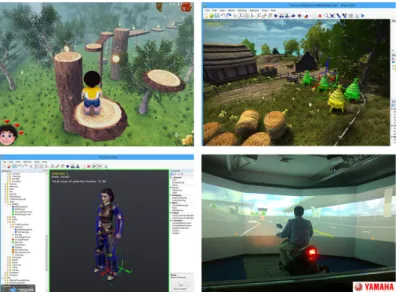
The NeoAxis 3D Engine is a free integrated development environment that allows the creation of video games, the development of simulators as well as virtual reality and visualiz-ation software. It includes a full set of tools for fast and logical development of 3D projects. It uses C# with the .NET 3.5 framework as programming language and the rendering is done by OGRE. Using the .NET framework makes it possible to integrate this 3D engine within WPF applications, which was one of our main requirements.
Figure 3.2: NeoAxis 3D Engine - Examples of two applications and the Map and Resource editors.4 2 http://helixtoolkit.codeplex.com/ 3 http://www.neoaxis.com/ 4http://www.neoaxis.com/showcase/screenshots
3.3
Implementation of the proposed methods
Before explaining how the methods were implemented, it must be clarified that the co-ordinate system from the Kinect sensor is different from the one used by NeoAxis 3D engine. As illustrated in Figure 3.3, the axes from both systems are oriented in a different manner. Therefore, for all methods implemented (navigation included), a conversion between these coordinate systems must take place.
In this dissertation, and in this chapter in particular, the NeoAxis system represented in Figure 3.3 (b) will accompany all diagrams describing the methods, indicating in which axis each manipulation will occur. All transformations mentioned are performed in this coordinate system. The Kinect coordinate system (Figure 3.3 (a)), must be considered when hand, grab or skeleton points are mentioned, as they are determined by the Kinect SDK.
Figure 3.3: The two coordinate system used in this dissertation. (a) Kinect coordinate system. (b) NeoAxis 3D engine coordinate system.
3.3.1 OneHand
Our first approach was to manipulate a 3D virtual object with a single hand, using the cursor-based metaphor of grabbing and manipulating it with the hand movement. We im-plemented the ”OneHand” method(Figure 3.4) in which the rotation is determined using the offset between the grabbing point (where the grab gesture was first detected) and the position of the moving hand. The Microsoft Kinect SDK provided us with the grab and release events for user’s dominant hand.
Figure 3.4: Diagram of the ”OneHand” method.
Z axis are determined using the 2D coordinates of the hand cursor (screen space), provided by the KinectRegion from SDK controls.
Since the rotation of every object on NeoAxis engine is described by a four-dimensional vector space (Quaternion), we have implemented a function to generate a quaternion from an angle and a direction (GenerateQuat). This direction will describe the axis in which the rotation value will be applied. After we have calculated the quaternions for each axis, the object rotation will consist of the multiplication between this two quaternions and the accumulated rotation.
Regarding the accumulated rotation, this defines all previous transformations and is up-dated each time a hand release event occurs. We simply store the current object rotation at this variable.
As mentioned before, for this method the scale manipulation is implemented using two GUI buttons (Figure 3.4 (b) ). By pressing continuously either button it is possible to increase or decrease the scale factor of the 3D object.
Algorithm 1: Algorithm to determine the object rotation in the ”OneHand” method.
input : GrabPoint, HandCursor forall the render tick event do
if grab event then
yOffset = GrabPoint.Y − HandCursor.Y ; zOffset = GrabPoint.X − HandCursor.X ;
rotY = GenerateQuat( Vector(0,1,0 ) , yOffset ) ; rotZ = GenerateQuat( Vector(0,0,1 ) , zOffset ) ; object rotation = rotY ∗ rotZ ∗ accumulated rotation; else
accumulated rotation = object rotation; end
3.3.2 Handle bar
It was clear after some preliminary tests, that the ”OneHand” method had some limita-tions, specifically in the rotation, since it forced the user to perform many rotation manipu-lations to reach the desired orientation. This was due to the cursor-based movement, which implied a mapping of a 2D coordinate space of the cursor to the 3D space of the object. Also, there was the constraint of the Kinect sensor not being able to detect the wrist orientation, not enabling the implementation of all 3 DOF of the rotation.
As opposed to the “OneHand” method, in the method “HandleBar” (Figure 3.5) manipu-lation occurs in 3D space, in which the 3D coordinates of the user’s hands are mapped directly for the manipulation of the object.
This method implements an handle bar metaphor based upon the experiments of [Song et al., 2012]. This metaphor consists of a bimanual interaction to manipulate a single object, using the grab and release gestures. We position a virtual handle bar at the center of the 3D object and it will represent the relative orientation of the users’ hands, providing a helpful visual feedback.
Figure 3.5: Diagram of the ”HandleBar” method. (a) Top view, rotate around Z axis. (b) Front view, rotate around X axis. (c) Scale manipulation.
For this method, we could not rely on the KinectRegion to obtain the hands position and state. So, in order to obtain the 3D positions for the hands we had to access the processing of the skeleton data from the Kinect SDK (Figure 3.6). This was done using the SkeletonFrameReady event, which is fired at the end of the processing of the skeleton data stream by the SDK. A skeleton composed by 20 joints is constructed or updated and the hands positions are retrieved by storing the position of the respective joints from the skeleton.
After this step we do not have the hands state (open, grabbing or pressing); this informa-tion is not available on the skeleton data stream meninforma-tioned above. The hands state can only be accessed by introducing in the application the KinectInteraction Application Program-ming Interface (API). This API provides the InteractionFrameReady event, where the SDK constructs a data structure comprising all the information about the user’s hands.
Algorithm 2 presents how the rotation and scale were implemented for this method. The rotation was implemented for 2 DOF as was done for “OneHand”. For each axis, the rotation of the object is based on the relative offset of the handle bar rotation (hands position). When both hands are closed (grab) the current rotation of the object is temporarily stored, and the offset is determined based upon the position of each hand. Then, similarly to the “OneHand”,
Figure 3.6: Skeleton model used by the Kinect SDK ([Microsoft, 2013b]).
we have the quaternion calculation. This time the vectors for the direction are different, since the rotation DOF differ from the previous method.
Figure 3.5 (a, b) shows the two rotations implemented: to rotate the object around the Z axis, the user must move one of his/her hands forward and the other backwards, we map the angle between the imaginary line between both hands and the X axis of the object to the rotation of the object. To rotate around the X axis, one hand must move one up and the other down, and the angle of the rotation is calculated between both hands and the Y axis of the object.
No absolute angular mapping is needed since each time the user opens at least one hand, the rotation is stored and the user may re-initiate a bi-manual grab gesture at a new position and perform a further rotation. This allows the user to make large angular changes to the 3D virtual object about the two axes without getting into an undesirable situation where, for example, the front hand occludes the back hand, making impossible to determine the rotation.
The object scale is calculated using the distance between the left hand and the right hand, the further the hands, the larger the object. Again we used an accumulation strategy, enabling user to perform successive scale operations. When the user reaches his/her maximum arm stretch or both hands are close together, he/she can release the manipulation by opening at least one hand; this event causes the storage of the current scale of object, and the user can return the hands to another position and start another manipulation.
Also, a color scheme gives feedback to the user if both hands are opened (white) and if both hands are in the grabbing state (green).
Algorithm 2: Algorithm to determine the object rotation and scale in the ”HandleBar” method.
input : HandLeft, HandRight forall the render tick event do
if left and right hands grab event then if grabbing is false then
GrabbedScale = Distance(HandLeft, HandRight) ; GrabbedX = rotationX ;
GrabbedZ = rotationZ ; grabbing = true ; end
//
// calculate and set the object’s rotation //
rotationX = (HandLeft.Y − HandRight.Y) ; rotationZ = (HandLeft.Z − HandRight.Z) ; xOffset = GrabbedX − rotationX ;
zOffset = GrabbedZ − rotationZ ;
rotX = GenerateQuat( Vector(1,0,0 ) , xOffset ) ; rotZ = GenerateQuat( Vector(0,0,1 ) , zOffset ) ; object rotation = rotX ∗ rotZ ∗ acumulated rotation ; //
// calculate and set the object’s scale //
scaleValue = Distance(HandLeft, HandRight) ; scaleOffset = GrabbedScale − scaleValue ; scale = accumulated scale - ScaleOffset ;
if scale > min threshold and scale < max threshold then object scale = scale ;
end else
accumulated rotation = object rotation ; accumulated scale = object scale ; grabbing = false ;
end end
3.3.3 Improved Handle bar
As mentioned before, during the analysis of the results obtained during the preliminary evaluation tests of the previous method (see Section 4.1.2), some users proposed a way to improve the “HandleBar” method (Figure 3.7) by suggesting that we could use both hands movement in the same direction (up or down) to introduce the missing rotation DOF (Y axis).
Figure 3.7: Diagram of the improved HandleBar method.
This improvement was implemented first by checking if both hands are in the grabbing state. Then we analyse if both hands are parallel with each other, i.e. the hands are at the same height. If these conditions are verified during the interaction, we determine the angle between the Y axis (Kinect coordinate system) and the imaginary line going from a reference position (the hip center joint) to the middle point between both hands; with this distance we determine the rotation. This implies that the hip center joint position was retrieved from the skeleton data in each frame. Then the algorithm is similar as described above for the original “HandleBar” method. This improvement provided the full rotation DOFs.
In order to give visual feedback about the different rotations, we added an extra condition to the color scheme of the handle bar; if the new gesture is detected (Table 3.1).
Gesture Rotation Color
At least one of the hands OPENED None White
Both hands CLOSED X and Z axes Green
Hands parallel to each other Y axis Orange
3.3.4 Handle bar with user representation 3.3.4.1 Hands Avatars
During the evaluation of both versions of the ”HandleBar” method and after analysing the questionnaires (Sections 4.1.2 and 4.2.6), we have considered that users misinterpreted the usage of the handle bar 3D model as the representation of the user’s hands. This handle bar model rotated accordingly with the hands position and most of the users were not considering it helpful to determine where in 3D object space the hands were located.
Thus, an animated 3D model of the hand (Figure 3.8)was used. This change was imple-mented using a feature of NeoAxis 3D Engine that enables the 3D models to have a skeleton attached. The rotation of the skeleton bones modifies the object mesh accordingly.
Figure 3.8: Animated 3D model of the hand used in the ”HandleBar” method with user representation.
NeoAxis allows to import pre-established animations for the skeleton of a specific model. This is how we were able to import the animations for closing and opening the hand mimicking the grab gesture detected by the Kinect.
The animations are loaded within the 3D model during the import, in which we establish the range of the frames corresponding to each animation (e.g. grabToIdle - from frame 45 to 80). Then a script containing what NeoAxis calls animation tree needs to be configured in order to establish how the animations are called during run-time. This script indicates the states (grab and released) and the transitions between both states (See Figure 3.9). For each transition the corresponding animation is called automatically by the 3D engine, every time we invoke the opposite state.
Implementing this animation mechanism in conjunction with the detection of the grab gesture using the KinectInteraction API previously mentioned (Section 3.3.2), we were able to implement the visual feedback that indicates the state of the user’s hands during the manipulation.
The avatars’ positions are determined by mapping the data coming from the Kinect re-lative to the hands joints (skeleton info). We consider the torso as anchor and subtract its position (with an offset) from the hands position. Then slight adjustments offset the 3D positions of the models in order to bring them into view (See Figure 3.10). This way we determine that the 3D object is located in front of the user and the hands move around it.
Figure 3.10: Avatars of the hands in the ”HandleBar” method with user representation.
3.3.4.2 Full-Body Avatar
After integrating avatars for the hands, we considered that in some situations it might be helpful to use a representation of the user’s full body.
This was an exploratory work, aimed at establishing the groundwork of the tools for mapping the skeleton provided by the Kinect to a 3D human model. Our goal was to conduct a usability test in the future, in which we would assess the interaction with public displays using a full-body avatar and its usage in manipulation and navigation methods.
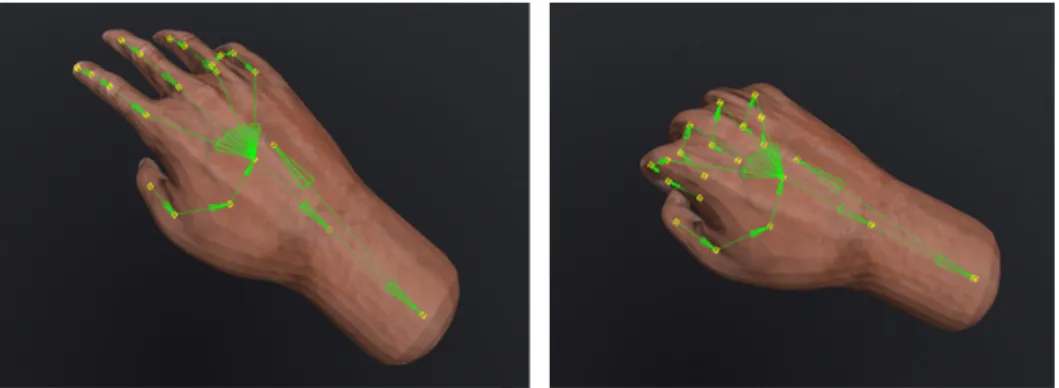
We tried to implement an avateering module in which we could animate a 3D model of a human character using the Kinect and NeoAxis (See Figure 3.11). One issue that must be taken into consideration, is that there must be a correlation between the skeleton of the 3D model that will be animated and the one from the Kinect (e.g. number of bones or joints). Although it is possible to match different skeletons with the one provided by the Kinect (e.g. disparity in the number of joints), the mapping between them could become a very complex task. Thus, we used a 3D model with an identical skeleton to one provided by the Kinect.
We have used the avateering example5 from the Kinect SDK as guide, which consists of a sample application where a humanoid avatar model is animated using Kinect and XNA, a set of tools for video game development that was discontinued by Microsoft, as mentioned previously.
Figure 3.11: Correlation between the skeleton of the fully rigged 3D model of a human character and the skeleton obtained from the Kinect SDK6.
We have used this example’s approach, in which the bone orientations were used for the animation. As the approach of changing the joint positions for the animation often causes problems of stretching the 3D model. For example, when the skeletons from both 3D model and Kinect differ in size, certain parts of the 3D mesh will be stretched. Therefore, using bone orientations enables any 3D model to be animated without stretching.
The Skeletal Tracking pipeline from the Kinect SDK defines its own skeleton and sets each bone orientation. The next step is a process that is called “re-targeting”. This process consists in converting from the Kinect SDK’s Skeletal Tracking joint locations and bone orientations to the 3D model in the NeoAxis.
We have implemented a data structure (DETI Bone) in which a direct map between bones can be established: NeoAxis and Kinect bones. At loading time, a skeleton (DETI Skeleton) composed by the information about the 3D model in NeoAxis is defined, in which for all bones of the model a DETI Bone is instantiated. Then, in the Skeleton-FrameReady event for each bone being tracked, we check its name and store its information in the corresponding DETI Bone.
Because of the different axis systems used between NeoAxis and Kinect SDK (Section3.3), the orientations had to be transformed according to the NeoAxis axis system. There were some joints, in which its axis systems were swapped (Figure 3.12), which required the re-ordering of some axes by swapping the components of the bone orientation quaternion. Because of the disparity between both skeletons, it the introduction of manual rotations (90 degrees) for the arm and leg bones was required in order to correct their orientation.
![Figure 2.1: DETI-Interact public display, [Dias et al., 2014].](https://thumb-eu.123doks.com/thumbv2/123dok_br/15721198.1070487/28.892.191.717.168.447/figure-deti-interact-public-display-dias-et-al.webp)
![Figure 2.3: LookingGlass public display - field-study and the three user representations: No Representation, Silhouette, and Image, [M¨ uller et al., 2012].](https://thumb-eu.123doks.com/thumbv2/123dok_br/15721198.1070487/31.892.275.629.279.654/figure-lookingglass-public-display-representations-representation-silhouette-image.webp)
![Figure 2.4: ChainedDisplays public display - three configurations allow different social exper- exper-iences by the same system, [Koppel and Walter, 2012].](https://thumb-eu.123doks.com/thumbv2/123dok_br/15721198.1070487/32.892.273.627.165.407/figure-chaineddisplays-public-display-configurations-different-koppel-walter.webp)
![Figure 2.5: Handle bar metaphor for virtual object manipulation with a set of recognizable hand gestures, [Song et al., 2012].](https://thumb-eu.123doks.com/thumbv2/123dok_br/15721198.1070487/33.892.207.698.692.991/figure-handle-metaphor-virtual-object-manipulation-recognizable-gestures.webp)
![Figure 2.7: Multi-hand gestures interaction system for architectural design developed by [Shiratuddin and Wong, 2011].](https://thumb-eu.123doks.com/thumbv2/123dok_br/15721198.1070487/35.892.227.678.781.1056/figure-multi-gestures-interaction-architectural-design-developed-shiratuddin.webp)
![Figure 2.11: Using a flying broomstick as the metaphor for a gesture based navigation through 3D environments, [Ren et al., 2013]](https://thumb-eu.123doks.com/thumbv2/123dok_br/15721198.1070487/38.892.237.663.717.953/figure-using-flying-broomstick-metaphor-gesture-navigation-environments.webp)
![Figure 2.12: Right: Camera manipulation using user’s gestures. Left: Set of recognizable gestures for camera manipulation, [Kim et al., 2012].](https://thumb-eu.123doks.com/thumbv2/123dok_br/15721198.1070487/39.892.226.684.303.578/figure-right-camera-manipulation-gestures-recognizable-gestures-manipulation.webp)