Mechanical performance of soil monolith collectors of adjustable dimensions
Desempenho mecânico de um coletor de monolitos de solo de dimensões
ajustáveis
DOI:10.34117/bjdv6n8-290
Recebimento dos originais: 15/07/2020 Aceitação para publicação: 18/08/2020
Marcio Venzon
Professor, Doutor do Departamento de Engenharia Mecânica, Universidade Federal de Rondonópolis -UFR
Avenida dos Estudantes, 5055, Cidade Universitária, Rondonópolis –MT, CEP: 78736-900 -Brasil E-mail: [email protected]
Tonny José Araújo da Silva
Professor, Doutor do Departamento de Engenharia Agrícola e Ambiental, Universidade Federal de Rondonópolis -UFR
Avenida dos Estudantes, 5055, Cidade Universitária, Rondonópolis –MT, CEP: 78736-900 -Brasil E-mail: [email protected]
Edna Maria Bonfim-Silva
Professora, Doutora do Departamento de Engenharia Agrícola e Ambiental, Universidade Federal de Rondonópolis -UFR
Avenida dos Estudantes, 5055, Cidade Universitária, Rondonópolis –MT, CEP: 78736-900 -Brasil E-mail: [email protected]
Renato Tillmann Bassini
Professor, Doutor do Departamento de Engenharia Agrícola e Ambiental, Universidade Federal de Rondonópolis -UFR
Avenida dos Estudantes, 5055, Cidade Universitária, Rondonópolis –MT, CEP: 78736-900 -Brasil E-mail: [email protected]
William Fenner
Doutor em Agricultura Tropical, Universidade Federal de Mato Grosso -UFMT
Av. Fernando Corrêa da Costa, nº 2367, Bairro Boa Esperança - Cuiabá – MT, CEP: 78060-900 - Brasil
E-mail: [email protected]
ABSTRACT
Scientists across the globe face a large challenge during representative soil sample collection when having to carefully retain the physical-chemical structure of the soil. The goal was to validate the performance of a mechanical collector of soil monoliths of adjustable formats and to establish suitable mechanical indicators of the operational equipment. The collector's operating ability, efficiency, and precision were confirmed in terms of the aspects listed: definition of the optimal rotation of work; maintenance of a uniform diameter and height of the monoliths in cylindrical and conical formats; collection efficiency under unfavorable conditions (roots and gravel presence); specification of the ideal soil moisture levels for collection from the various types of soil classes; collection from terrain characterized by uneven topography and evaluation of the wearing out of cutting tool edges (drill).
The data were analyzed using the coefficient of variation and a confidence interval test (p < 0.05). The monolith collector was very efficient, showing a high degree of precision during the sample collection, cutting the samples between 0.15 and 0.80 m in diameter for the cylindrical shaped particles and between 0.17 and 0.50 m for the conical ones. However, soil moisture levels exceeding 18 % limited the equipment’s performance on clayey soils.
Keywords: Agricultural machine, Soil sampler, Undeformed sample. RESUMO
Cientistas de todo o mundo enfrentam um grande desafio durante a coleta de amostras de solo representativas, quando precisam manter cuidadosamente a estrutura físico-química do solo. O objetivo foi validar o desempenho de um coletor mecânico de monólitos de solo de formatos ajustáveis e estabelecer indicadores mecânicos adequados para a operação do equipamento. A capacidade operacional, a eficiência e a precisão do coletor foram confirmadas de acordo com aspectos listados: definição da rotação ideal do trabalho; manutenção de diâmetro e altura uniformes dos monólitos de solo nos formatos cilíndrico e cônico; eficiência de coleta em condições desfavoráveis (presença de raízes e cascalho); especificação dos níveis ideais de umidade do solo para coleta dos vários tipos de classes de solo; coleta do terreno caracterizada por topografia irregular e avaliação do desgaste das bordas da ferramenta de corte (broca). Os dados foram analisados pelo coeficiente de variação e teste de intervalo de confiança (p <0,05). O coletor de monólitos é eficiente, demonstrando alto grau de precisão durante a coleta, coletando amostras entre 0,15 e 0,80 m de diâmetro para as partículas cilíndricas e entre 0,17 e 0,50 m para as cônicas. No entanto, níveis de umidade do solo superiores a 18% limitam o desempenho do equipamento em solos argilosos.
Palavras-Chave: Máquina agrícola, Amostrador de solo, Amostra indeformada.
1 INTRODUCTION
All agriculture-related experiments frequently occur first under controlled conditions, needing to represent natural conditions. In fact, the care required in preserving soil structure for later use in related experiments can be traced to Russia, from the 19th century, and the first studies using monoliths (Allaire; Bochove, 2006; Haddad et al., 2009).
Apart from this, monoliths have found wide usage in various fields of science, including some aspects of soil physics (Paludo et al., 2017), biology (Peres-Oliveira et al., 2017), microbiology, engineering, agrometeorology (Silvério et al., 2017), fertility, hydrology, and plant production in natural environments or greenhouses (Allaire; Bochove, 2006). The model of the sampler and the operator may cause many errors during collection, such as changing the bulk density and soil porosity (Souza et al., 2014).
The soil tillage performed for usage in pots induces alterations in the physical features and affects the water dynamics (Hillel, 1982). Such modifications influence the chemistry, nutrient distribution and can produce a concentration gradient (Gatiboni et al., 2007).
When field experiments are performed in no-tillage systems and under controlled conditions, the original physical properties of the soil need to be preserved as much as possible (Bortolon et al.,
2009). Currently, all assessments performed on soil, most of which are collected in an approximately 100 cm³ sized sample, presume that the collection methods employed did not induce any changes in the sampled soil structure.
Soil samples showing a deformed structure are employed to identify the chemical composition and certain physical properties such as water content, grain size, and specific particle mass, in addition to others. This means that not altering the soil’s physical conditions is crucial (Allaire; Bochove, 2006; Bortolon et al., 2009).
The soil monoliths collected using this equipment extends beyond the use of plastic containers and can provide a speedy and precise collection of soil monolith, larger than those the conventional sizes (0.05 to 0.60 m) (Allaire; Bochove, 2006; Souza et al., 2014), and that can show diversity in diameters and shape are not currently common or easily available.
Thus, this work aimed validate the performance of a mechanical collector of soil monoliths of adjustable dimensions and to establish suitable mechanical indicators of the operational equipment.
2 MATERIAL AND METHODS
GENERAL CHARACTERIZATION
The soil monolith collection equipment was developed, constructed, and evaluated at the Rondonópolis, Mato Grosso State - Brazil, located geographically at 16°27’44.71’’ S, 54°34’48.54’’ W and 290 meters elevation. The following are construction details and operating principles, as well as general aspects of the operation of the soil monolith collector and its evaluation procedures.
COLLECTOR SPECIFICATIONS AND CONSTRUCTION DETAILS
To accomplish this, an implement made up of carbon steel (Society of Automotive Engineers - SAE 1020) working on the principle of "mechanical machining" was developed. This principle is defined as a mechanical operation that confers a defined shape to a component using a cutting tool with the removal of material. In the case of the implement, the defined shape is the soil monolith and the material removed is the soil disaggregated and transported by the helical drill (Groover, 2011). Using the hydraulic power provided by an agricultural tractor hydraulic pump, machine movements were achieved. This equipment was constructed and developed to facilitate the collection of cylindrical or conical shaped monoliths through mechanisms that the operator can adjust and to enable monoliths of varying diameters and shapes to be collected.
Keeping in mind the operating principle of retaining and preserving the physical integrity of the samples, soil "machining" was done during sample collection, at which time the soil was mechanically thinned with the cutting edge of the tool, in a cylindrical format (Groover, 2011). Soil
friction compaction is thus minimized for the sampler. In addition, the shearing resulting from the sampling cylinders employed in the traditional methods (such as sampler type kopeck and Uhland) was reduced and the machine retained the natural soil structure in the samples collected.
In comparison to the term "cutting", “shaving” refers to soil physics studies regarding the preparation of the sample by eliminating excess soil, when soil density or other physical parameters are to be determined. While the soil volume was being adjusted to the collection cylinder, the hand "cutting" process of the soil (hand finishing) was performed, using adequate tools for soil thinning.
To achieve this, accessories such as a spatula, knife, saw blade, stylet, etc. were utilized to adjust the soil volume in volumetric rings. The cutting implement, which produces a mechanical roughing operation through manual effort, was used at the ends of the volumetric ring. As an analogy, the equipment developed in this study used a cutting tool, very similar to a drill, with which the "shaving" operation of the soil was accomplished through the rotary movements developed using the hydraulic energy provided by the system.
The cutting tool developed and used in the monolith sample collection possesses four cut-off edges, 90° apart, at an approximately 30° exit angle (Figure 1A), with a 0.11 m diameter, resulting in a helical drill. During the collection, this tool enables a cutting slot to be opened between the soil and the monolith, making the subsequent removal of the monolith easier (Figure 1B).
Figure 1: A - Cutting edges of the cutting tool; B - Space between the soil and the monolith realized by the cutting tool in the clay soil, Rondonópolis, Mato Grosso State - Brazil, 2014.
The equipment thus developed functions by coupling it to an agricultural tractor (Manufacturer AGCO, model Massey Ferguson 292 Advanced, 112 c.v. - 4x4) having a hydraulic system that can couple the external implements (Figure 2). The equipment can be coupled to other tractors with similar characteristics.
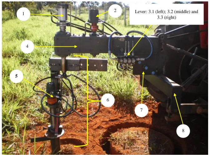
Figure 2: Technical details of the equipment components, 1 - Rotative union (for circular motion and for fluid transfer; allows the helical drill to operate and move up and down); 2 - Hydraulic motor [when actuated, is responsible for the operation of the rotary helical drill system (360 degree rotation movement)]; 3 - Directional control valve bank; 4 - Chassis; 5 - Hydraulic motor of the helical drill; 6 - Rotary helical drill system; 7 - Flow control valve and 8 - Mounted on the tractor´s three-point hitch. Rondonópolis, Mato Grosso - Brazil, 2014.
In the actual building of the cutting tool of the sampler, high tensile strength steel SAE 1085 was used, with high mechanical strength and a high fatigue limit; it was welded and finally, its cutting edges were shaped using a hand grinder.
EQUIPMENT OPERATION
Driven by hydraulic forces, this equipment had the transmission of its movements done through converting the hydraulic force on the motor shaft into a mechanical rotation force (torque). A gear pump in the agricultural tractor and the oil volume (flow) were directly dependent on the rotation transmitted to the hydraulic force.
Thus, the flow that was directly proportional to the rotation of work necessitated calibration as the ideal helical drill rotation of work. This means that the greater the rotation of the pump shaft was (coupled to the tractor), the greater the oil flow (up to the flow limit, which was 80 L min-1, for the tractor model used) and, consequently, the higher the torque and rotation of the helical drill.
2
1 Lever: 3.1 (left); 3.2 (middle) and
3.3 (right) 4 7 6 8 5
The components are described and listed in Figure 2 and the operation and running processes were as follows: After positioning the tractor at the desired place of collection, the operator performed a leveling of the equipment (4) by means of mounting on the tractor´s three-point hitch (8) and adjusting the diameter for cutting of the soil monoliths in the upper part of the rotary drill system (6) (details of the adjustment of diameter can be seen in Figure 3).
Figure 3: A - By loosening these two screws, it is possible to make the desired diameter adjustment. Moving the rotary helical drill system to the left decreases the diameter; moving it to the right increases the diameter. With the adjustment done, the screws are tightened for work; B - Adjustable rotary drill system holder and C - Fixed bracket.
The tractor was operated with the parking brake, and the operator selected the ideal working rotation [any revolution in the range between 1300 and 1500 RPM (Revolutions Per Minute) of the tractor engine to provide a hydraulic pump flow of approximately 80 L min-1] to start collecting the soil monolith. The operator then actuated the helical drill bit by means of the first hydraulic control lever (3.1) and then activated the second lever (3.2) to start the rotary drill system (6). The operator then began to insert the helical drill bit into the ground using the third hydraulic control lever (3.3), which moves the helical drill (up or down) by means of a linear hydraulic actuator that is actuated by the hydraulic control. The desired depth must be measured with a ruler or a measuring tape. As the helicoid pulls out of the ground, the operator advances the drill down to the desired depth. After all the soil is removed by the helicoid, the operator returns the drill to the initial position and removes the tractor from its place to finish the removal of the monolith and its transportation. The rotation of the rotary drill system (6) and drill bit can be changed using the flow control valve (7) according to the operating conditions and soil type. The tractor remains totally stopped during collecting of the soil monoliths. Only the rotary helical drill moves in a circle during the operation.
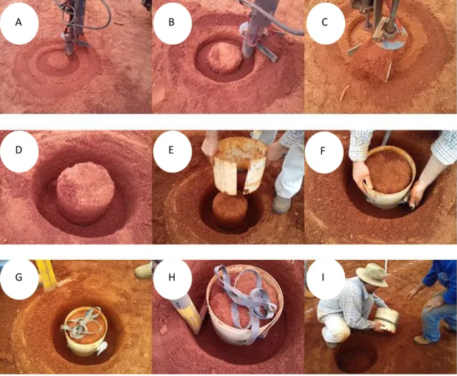
Thus, once the "cutting" process is over, the monolith can be removed from the soil using either a metal wrap or Polyvinyl Chloride (PVC); it is preferable to bubble wrap it to ensure safe transportation, by preventing any disintegration after collection, during transport (Figure 4).
Figure 4: An operational sequence of soil monoliths collected in the clay soil. A and B - Cutting the soil monolith with the equipment; C - The flat steel bars contain loose soil in the upper part of the helical drill, and the possibility exists to transfer the soil in the drill to the outside. D - Soil monolith prepared; E - Involving the soil monolith with the Polyvinyl Chloride (PVC) tube; F – Fixing the PVC tube with a belt and ratchet (suggestion only, to aid removal and
transportation); G - Soil monolith prepared for removal; H - Cutting the base of the soil monolith with a spatula (four cuts around are sufficient to break the base of the soil monolith) and I - Removing the soil monolith. Rondonópolis, Mato Grosso - Brazil, 2014.
COLLECTED VARIABLES
Preliminary tests were done on the equipment to verify its operation and effectiveness. The preliminary tests were not intended to evaluate performances of the equipment or soil monoliths collected but only to verify the equipment's operation and certify the operation of the mechanical and hydraulic components of the system, as well as to carry out the equipment performance evaluation tests and the quality of the soil monoliths collected in the second step. Then, tests were performed using four soil classes, differing in diameters of soil monoliths collection and under unfavorable operating conditions (the presence of gravel and excessive soil moisture), to identify the mechanical resistance, mostly in terms of wearing out of the cutting edge of the tool due to abrasion and friction while in ground contact.
The collecting equipment was then subjected to performance tests, as the monolith sample collections were conducted in the rural areas in the south of the Mato Grosso State, from four textural
A B C
D E F
classes of soils (Table 1): Soil I - clay; Soil II - sandy loam; Soil III -sandy clay loam; Soil IV – sand (Soil Survey Staff, 2014).
Table 1: Physic-hydric characterization of soils used in tests of the soil monolith collector, Rondonópolis, Mato Grosso - Brazil, 2014.
Soil Sand* Silt* Clay* WFC ρs
I 423 133 444 0.28 1.33
II 692 233 75 0.29 1.34
III 562 199 243 0.21 1.57
IV 890 66 45 0.25 1.40
WFC - Water Field Capacity (m3 m-3); ρs - Bulk density (Mg m-3); * g kg-1.
The performance test involved the collection of six monolith samples for each textural soil class from the superficial layer (0 - 0.30 m) and six soil monoliths from irregular terrain, all with a diameter of 0.24 m. The collection points were maintained within a 10-meter radius to maintain a uniform soil sample. Thus, 30 soil monoliths were collected in total to perform the tests.
The following tests were done at the time of the collection: I - The optimum helical drill work rotation of the equipment was determined and time of collection; II - The collected monolith samples of varying diameters for the conical and cylindrical formats were evaluated; III - The variation of the diameter and depth of the monoliths; IV - Monolith samples from the soils with roots present were collected; V - Monolith samples from the soils with gravel present were collected; VI - Samples from soils showing variations in soil moisture levels were collected; VII - Monolith samples collected from regions of uneven topography were collected; and VIII - Wearing off of the edges of the cutting tool was assessed (helical drill).
To determine the work rotation of the helical drill (test I), an optical (non-contact) Victor brand DM 6236P tachometer was used, and the measurements were performed directly on the axis of the helical drill. The parameter work rotation involved the drive axis of the cutting tool because this mechanism produced the greatest rotation confirmed at the time of the assembly of the equipment. The cutting tool revolutions were measured, starting at 700 RPM of the tractor diesel engine, recording a rotation of 140 RPM in the cutting tool axis. The tractor engine used an increment of 100-by-100 RPM in the test (between 700 and 2100 RPM), and for each tractor rotation, the value of the resulting rotation in the cutting tool axis was recorded.
For the assay (tests II and III), the various sized monolith samples, having diameters ranging from 0.15 to 0.80 m in the cylindrical formation, were collected and tested. Additionally, collection
tests were done on the monoliths with conical features and diameters between 0.17 and 0.50 m. The samples were placed in plastic containers like those usually utilized for plant cultivation and/or greenhouse experiments, but with an approximately 7º angle.
Throughout the equipment testing process, approximately 100 monoliths representing the four textural soil classes were machined under the most diverse situations, such as the presence of gravel and roots and in soils with varying moisture levels (tests IV and V).
Apart from this, 24 monoliths were also collected, while retaining the identical restriction of 0.24 m diameter, to test the consistency and repeatability of the equipment in maintaining the predetermined adjustment through successive operations and regions of uneven topography maintain the monoliths diameter (test VII). In terms of the soil moisture limits and operational performance of the equipment, tests were performed using a variety of soil humidity levels (test VI), with a uniform profile in relation to the depth. The moisture equivalent field capacity was identified as 29 %, and the monolith collection was performed under soil moisture intervals from 13 to 21 %.
Once the cutting tool was prepared, testing commenced. The monoliths were collected without repairing or sharpening the cutting edge of the tool to confirm its durability and the quality of the monoliths gathered over time (test VIII).
STATISTICAL ANALYSIS
The variables recorded during the equipment tests (tests I, II, III, VII and VIII) were assessed by the coefficient of variation (CV), classified as low - less than 10 %; average - between 10 and 20 %; high - between 20 and 30 %; and very high - over 30 % (Pimentel-Gomes, 2009). A comparison of the means of the data was done using the confidence interval of the mean at 95 % (p < 0.05) (Payton, 2000). This method involved two or more treatments being considered different when no overlap was evident between the upper and lower limits.
3 RESULTS AND DISCUSSION
Substantial differences were noted between the motor engine RPM and cutting tool, giving evidence for the necessity of identifying the ideal working range to induce the best performance of the collecting equipment while retaining the natural structure of the monolith (Figure 5).
Figure 5: Rotation of the cutting tool as a function of the Revolutions Per Minute (RPM).
For the tractor engine revolutions between 700 and 1300 RPM, larger variations were observed in the cutting tool revolutions, with the CV being reported as 14 %. For revolutions exceeding 1300 RPM, this variation dropped, with the CV being 1 %. When the rotation crossed 1500 RPM, the rotational increments on the shaft were noted to reduce.
These were attributed to this value being the maximum hydraulic flow rate of the tractor, in which no increase in flow was possible, resulting from the increased rotation. However, this did not prove to be limiting the equipment performance. Thus, the flow of the hydraulic pump at 1500 RPM in the tractor engine was sufficient for the optimum operation of the equipment.
The CV was average for revolutions between 700 and 1300 RPM, while it was low for revolutions above 1300 RPM (Pimentel-Gomes, 2009). In the field, while monolith collection was being done, the equipment was observed to have higher performance (maximum collection capacity) when the maximum rotation of the cutting tool was achieved, viz., at 210 RPM; this enabled the conclusion to be drawn that the ideal working range lies between 1300 and 1500 RPM on the tractor engine.
Within this range, we have the maximum flow of the tractor's hydraulic pump that provides the highest rotation of the helical drill with the lowest consumption of tractor fuel, lowest wear of components of the machine and tractor and maximum soil monolith collection capacity. Within this working range, the equipment generated a minimum level of vibrations. Any operation outside of this range can produce clogging in the collecting equipment or even the disposal of the collected soil monolith.
Regarding the diameter, this equipment enables the collection of soil monoliths with diameters between 0.15 (Figure 6A) and 0.80 m (Figure 6B) in the cylindrical format and from 0.17
130 150 170 190 210 230 5 7 9 11 13 15 17 19 21 D ri ll R o ta ti o n (R P M ) Tractor Engine RPM*100 O pe ra ti o n ra n ge
to 0.50 m in the conical format. The diameters presented are, respectively, the minimum and maximum sizes of the collection, defined by the equipment design. Any diameter within this range can be collected.
Figure 6: Cylindrically shaped monoliths with diameters of 0.15 (A) and 0.80 m (B) in the clay soil, Rondonópolis, Mato Grosso State - Brazil, 2014.
From the perspective of the sampling accuracy, the diameter was between 0.230 and 0.245 m (Figure 7), considering all the replicates and soil types collected. The samples thus collected showed a CV value of 1 %. In terms of depth, a variation of 0.228 to 0.270 m (Figure 8) was noted, with the CV being 4 %. A low CV reveals a high degree of precision of the equipment in maintaining the monolith structure.
Figure 7: Monolith diameter collected from the different soils (Soil I - clay; Soil II - sandy loam; Soil III -sandy clay loam; Soil IV - sand). The vertical bars represent the confidence interval (p < 0.05).
0,232 0,234 0,236 0,238 0,240 0,242 0,244 0,246 I II III IV Mo n o li th D ia m e te r (m ) Soil Class A B A B
No difference was observed between the diameters and depth of the monoliths collected, irrespective of the texture of the soil class, thus highlighting the efficiency of this equipment in terms of the uniformity of the samples collected (Figure 8 and 9).
Figure 8: Monolith depth were collected from the different soils (Soil I - clay; Soil II - sandy loam; Soil III - sandy clay loam; Soil IV - sand). The vertical bars represent the confidence interval of the mean (p < 0.05).
Figure 9: Soil monoliths collected from the different soil classes. A - clay; B - sandy clay loam; C – sand.
From the perspective of the collection depth, which refers to the final height of the monolith, the equipment developed enabled the collection of monoliths up to a maximum height of 0.27 m. This parameter was dependent on the terrain slope, roots present and equipment operating method. For the variations in both the diameter and depth of the monoliths observed in this work, the CV was found to be low (Pimentel-Gomes, 2009).
One significant factor to consider was the diameter uniformity observed in the monoliths, as the equipment could maintain uniformity of the circumference throughout the sample during the collections. In Figure 8, the soil monoliths collected from the different soil classes tested are shown, where the uniformity in the diameter along the height of the entire sample was verified. The likelihood of collecting larger monoliths varying in size and shape was the chief technological advancement in
0,22 0,23 0,24 0,25 0,26 0,27 0,28 I II III IV Mo n o li th D e p th (m ) Soil Class A B C
agricultural experimentation, as evidence proves that small samples, such as the ones normally used, are not representative, particularly in maintaining the physical structure of the soil (Allaire; Bochove, 2006).
Visual verification showed that the presence of roots of up to 0.005 m diameter in the soil did not limit the monolith collection. However, when roots of diameter greater than this were present (such as those of trees), they posed a difficulty in collecting the monoliths and could even cause damage to the equipment. The sandy clay loam soil contained high quantities of gravel with a 0.005 m mean diameter, as well as organic material and rotting vegetation. However, these factors were found to exert no limitation on the equipment performance.
The high soil moisture, however, was found to exert a negative effect on equipment operation. This implies that the lower the soil moisture is, the higher the equipment performance, particularly in terms of the soil flow carried away by the helical conveyor (such as an Archimedes screw) coupled to the cutting tool (drill). With the monolith collection being done under three levels of soil moisture (13, 18 and 21 %), it was easy to conclude that when monolith samples containing moisture levels above 18 % were collected, it posed a limitation on the equipment operation, causing problems in the helical conveyor, thus negatively influencing the collection quality.
For soil moisture levels below 18 %, the equipment performed satisfactorily, providing high-quality monoliths for each collection. This was attributed to the action of the cohesive forces and soil adhesion. When the soil was very wet, the adhesion effect was predominant (soil-water), as it altered the soil consistency by raising its plasticity and, in turn, caused equipment clogging. This phenomenon was absent when the soil was dry and when the attraction between soil particles of the same physical state (soil-soil) took place, enabling proper equipment functioning (Schaetzl; Anderson, 2005). Such an occurrence, although in greater intensity, was noted in the high-clay content soils.
The time taken for the collection of monoliths up to 0.30 m was between 00h05 and 00h10, of which 00h7.5 was the average. The collection of monoliths approximately 0.80 m in diameter was also recorded and found to take a mean time of 00h15 for mechanical soil roughing alone, and the time taken to remove the monolith (± 00h05) must be considered.
For the collection time of the sandy clay loam soil, the CV was found to be low, whereas for the other soils, the CV was medium when individual comparisons were performed for each soil type. For the mean collection time, the CV for all the soils was categorized as high (Pimentel-Gomes, 2009).
In the case of the collection time for the 0.24 m diameter monoliths and the different soil types, a statistically difference (p < 0.05) was noted using the mean confidence interval method
(Figure 10); this difference was produced by the collection time in the sandy clay loam, which possessed considerable quantities of gravel, necessitating the equipment to be operated with more caution to prevent mechanical damage to both the equipment and monolith.
Figure 10: Time taken for monolith collection from the different soils (Soil I - clay; Soil II - sandy loam; Soil III -sandy clay loam; Soil IV - sand). The vertical bars indicate the confidence interval of the mean (p < 0.05).
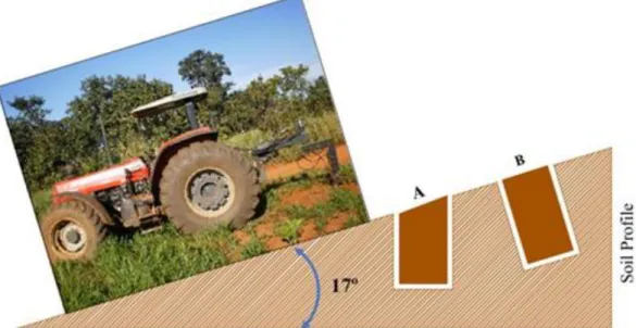
Soil monolith collection could be conducted vertically to the soil profile (Figure 11A), or adjustments could be made to the equipment for any angle from 0 to 17º, if necessary, to collect soil monoliths in areas with slope, enabling the monoliths to be collected perpendicular to the soil profile, up to a 17º slope (Figure 11B) in irregular terrains.
4 5 6 7 8 9 10 11 I II III IV C o ll e ct io n t im e (m in ) Soil Class
Figure 11: Illustration of the collection angle of the monoliths from sloping soils.
A 0.001 m wear of the cutting edges of the tool was recorded for every 100 monoliths collected, which was caused by friction between the soil and the cutting edge of the cutting tool, inducing a slight rounding. When this takes place, more mechanical power must be supplied to the shaft, which makes it more difficult to perform cutting actions and produces more tool deflection (Figure 12).
Figure 12: Illustration of the edge wear post-collection and removal of material for each adjustment done on the cutting tool.
However, the findings recorded demonstrate that the material selected to manufacture the cutting edge satisfied the conditions suggested at the time of developing the equipment; it was found
to be efficient with respect to the durability, mechanical strength and finishing of the monoliths collected, evidenced by the minimal wear on the cutting tool during the tests.
The marginal operational wear noted on the cutting edges (roundness shape) of the cutting tool was accepted as normal, as the reduction in the area that presented the cutting tool and the high degree of friction produced between the soil particles with the rotating movement of the tool caused this wear to occur. Although this is a natural problem, it can be easily overcome by sharpening the edges. The equipment proposed has a provision for the removal of the tool and for a fresh edging to be made using a hand grinder. During this edging process, approximately 0.001 m of the material is removed after every 100 monoliths are collected.
Considering the soils tested, parameters and procedures employed during the monolith collection, the total available tool height of 0.010 m, and the fact that after every 100th monolith, on average, 0.001 m will need to be removed for adjustment in the cutting edges, the tool developed permits the collection of approximately 1000 (thousand) soil monoliths. This proves its efficiency and durability, and the material used in its manufacture can be considered adequate.
4 CONCLUSIONS
The mechanical collector of soil monoliths developed presents satisfactory performance and has the capacity to cut undisturbed soil samples with minimal distortion to their physical structure and cut undisturbed samples with diameters from 0.15 m to 0.80 m for the cylindrical shape and 0.17 to 0.50 m for the conical shape.
The mechanical collector of soil monoliths has high-performance standards and facilitated the collection of soil monoliths, even when roots and gravel were present, in sizes up to 0.005 m and in a clay, sandy loam, sandy clay loam and sand soil classes.
Soil moisture higher than 18 % limit the quality of equipment performance on clayey soils. The cutting tool material used have adequate hardness, minimal wear, and high durability.
REFERENCES
ALLAIRE S.S.; BOCHOVE E.V. Collecting large soil monoliths. Canadian Journal of Soil Science, v.86, p.885-896, 2006.
BORTOLON L.; GIANELLO C.; CONTE O.; OLIVEIRA S.; LEVIEN R. Undisturbed soil sampling equipment for research in controlled conditions. Brazilian Journal of Soil Science, v.33, p.1929-1934, 2009.
GATIBONI L.C.; KAMINSKI J.; RHEINHEIMER D.S.; FLORES J.P.C. Bioavailability of soil phosphorus forms in no-tillage system. Brazilian Journal of Soil Science, v.31, p. 691-699, 2007. GROOVER M.P. Introduction to Manufacturing Processes. Wiley, Hoboken, NJ, USA, 720p, 2011. HADDAD N.I.; LAWRIE R.A.; ELDRIDGE S.M. Improved method of making soil monoliths using an acrylic bonding agent and proline auger. Geoderma, v.151, p.395-400, 2009.
HILLEL D. (1982) Introduction to soil physics. Academic Press, New York, NY, USA, 392p, 1982. PALUDO J.T.S.; BONFIM-SILVA E.M.; SILVA T.J.A.; ZANOTTO M.D.; FENNER W.; KOETZ M. Reproductive components of safflower genotypes submitted of bulk density levels in the Brazilian Cerrado. American Journal of Plant Sciences, v.8, p.2069-2082, 2017.
PAYTON M.E.; MILLER A.E.; RAUN W.R. Testing Statistical hypothesis using standard error bars and confidence intervals. Communications in Soil Science and Plant Analysis, v.31, p.547-551, 2000. PERES-OLIVEIRA M.A.; BONFIM-SILVA E.M.; SILVA V.M.; SILVA T.J.A.; SOUSA H.H.F. Soybean as bioindicator of residual effect of 2,4-D herbicide in an Oxisol from the Brazilian Cerrado. African Journal of Agricultural Research, v.12, p.35-41, 2017.
PIMENTEL-GOMES F. Curso de estatística experimental. FEALQ, Piracicaba, SP, BR, 451p, 2009. SCHAETZL R.; ANDERSON S. Soils Genesis and Geomorphology. Cambridge University Press, New York, NY, USA, 827p, 2005.
SILVÉRIO J.M.; SILVA T.J.A.; BONFIM-SILVA E.M.; IAIA A.M.; DUARTE T.F.; PIRES R.C.M. Drought tolerance of the sugar cane varieties during the initial development. Australian Journal of Crop Science, v.11, p.711-715, 2017.
Soil Survey Staff. Keys to Soil Taxonomy. USDA-Natural Resources Conservation Service, Washington, DC, USA, 2014.
SOUZA B.R.F.; JUNIOR C.A.S.; CARVALHO L.; PELLIN D. Soil sampler’s performance under different plant canopies in the region of Aquidauana-MS. Agrarian Academy, v.1, p.146-158, 2014.