MARIANA COSTA BERNARDES
TESE DE DOUTORADO EM ENGENHARIA ELÉTRICA DEPARTAMENTO DE ENGENHARIA ELÉTRICA
FACULDADE DE TECNOLOGIA
UNIVERSIDADE DE BRASÍLIA
FACULDADE DE TECNOLOGIA
DEPARTAMENTO DE ENGENHARIA ELÉTRICA
GUIDAGE ROBOTISÉ DES AIGUILLES FLEXIBLES
POUR DES PROCÉDURES PERCUTANÉES
MARIANA COSTA BERNARDES
TESE DE DOUTORADO SUBMETIDA AO DEPARTAMENTO DE ENGENHARIA ELÉTRICA DA FACULDADE DE TECNOLOGIA DA UNIVERSIDADE DE BRASÍLIA COMO PARTE DOS REQUI-SITOS NECESSÁRIOS PARA A OBTENÇÃO DO GRAU DE DOUTOR EM ENGENHARIA ELÉTRICA.
APROVADA POR:
Geovany A. Borges, ENE/UnB Orientador
Philippe Poignet, LIRMM/UM2 Orientador
Jocelyne Troccaz, CNRS/TIMC Examinador Externo
Guillaume Morel, ISIR/UPMC Examinador Externo
Chafiaa Hammitouche, ITI/Telecom Brest Examinador Externo
Nabil Zemiti, LIRMM/UM2 Examinador Interno
BERNARDES, MARIANA COSTA
Guidage Robotisé des Aiguilles Flexibles pour des Procédures Percutanées [Distrito Federal] 2012. xi, 127p., 210 x 297 mm (ENE/FT/UnB, Doutor, Engenharia Elétrica, 2012).
TESE DE DOUTORADO – Universidade de Brasília, Faculdade de Tecnologia. Departamento de Engenharia Elétrica
1. guiagem de agulha 2. planejamento de trajetória
3. robótica cirúrgica 4. agulhas flexíveis
I. ENE/FT/UnB II. Título (série)
REFERÊNCIA BIBLIOGRÁFICA
BERNARDES, M.C. (2012). Guidage Robotisé des Aiguilles Flexibles pour des Procédures Percutanées, TESE DE DOUTORADO em Engenharia Elétrica, Publicação PPGEA.TD.068/2012, Departamento de Engenharia Elétrica, Universidade de Brasília, Brasília, DF, 127p.
CESSÃO DE DIREITOS AUTOR: Mariana Costa Bernardes
TÍTULO: Guidage Robotisé des Aiguilles Flexibles pour des Procédures Percutanées. GRAU: Doutor ANO: 2012
É concedida à Universidade de Brasília permissão para reproduzir cópias desta tese de doutorado e para emprestar ou vender tais cópias somente para propósitos acadêmicos e científicos. O autor reserva outros direitos de publicação e nenhuma parte dessa tese de doutorado pode ser reproduzida sem autorização por escrito do autor.
Mariana Costa Bernardes
Departamento de Eng. Elétrica (ENE) - FT Universidade de Brasília (UnB)
Campus Darcy Ribeiro
R O B O T- A S S I S T E D S T E E R I N G O F F L E X I B L E N E E D L E S F O R P E R C U TA N E O U S P R O C E D U R E S
mariana costa bernardes
Guidage Robotisé des Aiguilles Flexibles pour des Procédures Percutanées
Guiagem Robotizada de Agulhas Flexíveis para Procedimentos Percutâneos
A B S T R A C T
This thesis proposes a robot-assisted approach for automatic steering of flexible beveled needles in percutaneous procedures. The method uses duty-cycled rotation of the needle to perform insertion with arcs of adjustable curvature, and combines closed-loop imaging feedback with an intraoperative motion replanning strategy to compensate for system uncertainties and disturbances. Differently from previous approaches, the closed-loop re-planning strategy is suitable for dynamic scenes that present changes of obstacles and target positions. Indeed, we implemented the proposed system using a robotic manipula-tor, and the results obtained fromin vitrotests confirmed the viability of our method. To the best of our knowledge, such results are original, specifically in what concerns the use of an intraoperative fast replanning strategy combined with needle duty-cycling and the use of a commercially available manipulator arm.
R É S U M É
Les travaux de cette thèse proposent une nouvelle approche pour le guidage assisté par robots d’aiguilles flexibles pour des procédures percutanées. La méthode est basée sur l’utilisation d’une rotation de l’aiguille avec un rapport cyclique variable pour réaliser une insertion avec des arcs de rayons de courbure différents. Elle combine un retour visuel avec une stratégie de planification adaptative pour compenser les incertitudes du système et les perturbations. Par rapport aux approches présentées précédemment dans la littéra-ture, la stratégie de planification en boucle fermée est adaptée à des scènes dynamiques qui présentent des changements de position des obstacles et de la cible. Cette approche a été implémentée sur un système robotique et les résultats obtenus in vitro confirment tout l’intérêt de cette technique.
R E S U M O
Esta tese propõe uma estratégia de guiagem robotizada de agulhas flexíveis com ponta chanfrada em procedimentos percutâneos. O método usa duty-cycle de rotação para rea-lizar inserções com arco de curvatura ajustável e combina realimentação de imagem em malha fechada com uma estratégia intraoperatória de replanejamento de movimento para compensar incertezas e distúrbios no sistema. Diferentemente de estratégias anteriores, o replanejamento em malha fechada é adequado a cenários dinâmicos em que há mudanças na posição do alvo e obstáculos. De fato, o sistema proposto foi implementado utilizando um robô manipulador, e os resultados obtidos de testes in vitro confirmaram a viabili-dade do método. Até onde se sabe, tais resultados são originais, especialmente no que diz respeito ao uso de planejamento rápido intraoperatório combinado comduty-cycleda agulha e o uso de um braço manipulador disponível comercialmente.
“Blessed are those who give without remembering. And blessed are those who take without forgetting.” —Bernard Meltzer
A C K N O W L E D G M E N T S
One of the joys of finishing a thesis is to look over the past and remember all the people who have supported me along this long process. The completion of this Ph.D. would not have been possible without the aid of countless friends from both Brazil and France, who have greatly influenced me during this journey. Now, it is finally the opportunity to thank them.
First, I would like to express my gratitude to my two advisors, Prof. Philippe Poignet and Prof. Geovany Araújo Borges, who are not only mentors but dear friends. I could not have asked for better role models on both academic and personal levels. I would also like to thank my examiners, Jocelyne Troccaz and Guillaume Morel, who provided encouraging and constructive feedback. It is no easy task reviewing a thesis, and I am grateful for their thoughtful and detailed comments.
Furthermore, I am thankful to the reviewers Chafiaa Hammitouche and Nabil Zemiti, for their insightful comments both in my work and in this thesis. I sincerely acknowl-edge Prof. Etienne Dombre for the very helpful remarks and encouragement he gave me whenever he was able to attend my presentations. A special thanks goes to Philippe Fraisse, Christine Azevedo-Coste, and Mitsuhiro Hayashibe, whose presence in my daily life served as inspiration and as example of the kind of scientist that I wish to be.
I gratefully acknowledge the funding sources that made my Ph.D. work possible. I was funded by the Coordenação de Aperfeiçoamento de Pessoal de Nível Superior (Capes) through the Colégio Doutoral Franco-Brasileiro Program (CDFB), and the scholarship pro-gram Demanda Social. Thanks also to the ANR ContInt USComp project, through which I had the necessary structure to develop my research activities, and its project manager, Alexandre Krupa, who has been extremely supportive during our joint laboratory activ-ities. In addition, I would like to express my gratitude to Michaela Müller and Euroflex GmbH, for their high quality nitinol samples.
It is also a pleasure to pay tribute to Murilo Marinho and André Augusto Geraldes, theneedle team. Their enthusiasm, intensity, and willingness to repeat experimental trials over and over again were a great source of motivation. My thanks to Marcella Cortat, who experimented and shared with me countless phantom recipes. I would also acknowledge Éderson Dorileo for his invaluable contribution with the image processing module, and for our many motivating discussions that I hope may result in a future cooperation.
The researchers and students of LIRMM have contributed immensely to my work and I would like to thank them for welcoming me as a friend and helping to develop the ideas in this thesis. I am especially grateful for the support of Pawel Maciejasz, Divine Maalouf, Alonso Sanchez, Chao Liu, Johann Lamaury, Alejandro González de Alba, Minh-Quyen Le, Kanty Rabenorosoa, and Nicolas Carlési. Other past students members that I have had the pleasure to work with or alongside of are Alfredo Toriz, Andreaa Ancuta, Lotfi Chikh,
particular Nicole Gleizes, Nicolas Serrurier, and Laetitia Megual, I am grateful for their solicitude and efficiency every time an administrative demand was necessary.
My time in France was also made enjoyable in large part due to the many people that became a part of my life. I am grateful for Tamara Chomont’s company in our memorable trips, and for the pleasant moments spent at LIRMM’s cafeteria with the folks from Mi-croelectronics: Gabriel Marchesan, Luís Vitório Cargnini, João Azevedo, Raphael Brum, Carolina Metzler, Guilherme Botorin, Bruno Paiva, Rafael Garibotti, Leonardo Zordan, and Luciano Ost (see, I did include your name in a publication!). Also, I could not forget the manysoiréesat Montpellier in the presence of Rogério Richa, Daniella Pingret, Natalia Nicole, Fernando and Giselle Fontainha, Flávia Calmon, Guilherme Sartori, Pedro Heitor Barros and Mariana Ferreira.
I am also in debt with my colleagues from Brazil, who have helped make my learning an enjoyable and stimulating experience. The LARA laboratory has always been a source of friendships as well as good advice and collaboration. My special thanks go to Luís Postinho Figueredo, Henrique Menegaz,Alberto Roberto Baptista, Eduardo Alves, Glauco Scandaroli, Pedro⇡ Santana, Claudia Ochoa, David Fiorillo, George Brindeiro, Felipe C. Beckmann Brandão, Bruno Amui, PedroFashion Dória, Rafael Cortes, and Thiago Rocha, who have stuck with me through the highs and lows of my academic life. In addition, I could always count on Pedro and Renata Moreira, Bruno Adorno, Polyana Pereira, An-tônio Bó, and Jovana Jovic, who gave me a home away from home. You have been like a second family, bearing the brunt of the frustrations, and sharing the joy of the successes; thank you for just being there for me.
Lastly, I wish to acknowledge my family, which has put up with my constant absences during the past years. Without their unconditional support, this journey would not have been possible. In special, I thank my parents, Antonio and Virgínia, who instilled within me a love of creative pursuits and science, all of which finds a place in this thesis. My sister, Fernanda, has also been the best of friends and her incentive during the final stages of this Ph.D. is so appreciated. And most of all, I wish to express my heartfelt gratitude for my loving, supportive, and patient husband Tiago, who encouraged me to accept the co-tutelle even if it meant that we would be apart for two years with an ocean between us (thank you, mon amour! All this sacrifice has finally paid off).
C O N T E N T S
List of Figures xiv
List of Tables xv
Acronyms xvi
introduction 1
1 state of the art 7
1.1 Steering Approaches and Devices . . . 7
1.1.1 Beveled needles . . . 9
1.1.2 Base manipulation . . . 10
1.1.3 Tissue manipulation . . . 11
1.2 Robot-assisted needle steering . . . 11
1.2.1 Needle steering motion planning . . . 12
1.2.2 Automatic needle tracking in medical images . . . 14
1.2.3 Image-guided control of steerable needles . . . 15
1.3 Conclusions . . . 16
2 needle modeling 19 2.1 Needle insertion forces . . . 19
2.2 Needle deformation . . . 21
2.2.1 Mechanics-based models . . . 21
2.2.2 Phenomenological models . . . 23
2.3 Beveled needle kinematic model . . . 24
2.4 Beveled needle insertion techniques . . . 27
2.4.1 Helical path . . . 27
2.4.2 Stop-and-turn . . . 28
2.4.3 Duty-cycling . . . 28
2.5 Conclusions . . . 29
3 beveled needle path planning 31 3.1 Path planning basic concepts . . . 32
3.2 Path planning for needle steering . . . 34
3.3 The Arc-RRT algorithm . . . 36
3.3.1 2D planning . . . 39
3.3.2 3D planning . . . 41
3.4 Intraoperative replanning . . . 44
3.5 Entry Point Planner . . . 45
3.6 Results and discussion . . . 45
3.6.1 2D planning evaluation . . . 46
3.6.2 3D planning evaluation . . . 50
3.7 Conclusion . . . 53
3.7.1 Summary . . . 53
3.7.2 Contributions . . . 54
4 beveled needle motion control 57 4.1 Beveled needle actuation . . . 57
4.1.1 Friction Drive and Telescopic Support devices . . . 57
4.1.2 Manipulator with telescopic support . . . 59
4.2 Steering module . . . 60
4.2.1 Duty-cycle control . . . 60
4.2.2 Insertion control . . . 62
4.3 Results and discussion . . . 66
4.3.1 Simulation results . . . 66
4.3.2 Experimental results . . . 69
4.4 Conclusion . . . 70
4.4.1 Summary . . . 70
4.4.2 Contributions . . . 71
5 robot-assisted beveled needle steering 73 5.1 Closed-loop steering system . . . 73
5.1.1 Adaptive motion planning . . . 74
5.1.2 Steering control . . . 77
5.2 Experimental Setup . . . 77
5.2.1 Calibration and identification procedure . . . 79
5.2.2 Initialization procedure . . . 80
5.3 Results and discussion . . . 81
5.3.1 Open-loop insertions . . . 81
5.3.2 Closed-loop insertions . . . 83
5.4 Conclusion . . . 88
5.4.1 Summary . . . 88
5.4.2 Contributions . . . 88
6 conclusions and perspectives 91 6.1 Concluding remarks . . . 91
6.2 Needle steering challenges . . . 92
appendix 95 a quaternions and dual quaternions 97 a.1 Mathematical background . . . 97
a.1.1 Quaternions . . . 97
a.1.2 Dual numbers . . . 98
a.1.3 Dual Quaternions . . . 98
a.2 Rigid body motion . . . 99
a.2.1 Rotations represented by quaternions . . . 99
a.2.2 Points and translations represented by quaternions . . . 99
a.2.3 Rigid motions represented by dual quaternions . . . 99
b manipulator kinematics in the dual task space 101 b.1 The dual task space . . . 101
b.2 The Standard Denavit-Hartenberg convention . . . 102
b.2.1 Coordinate frames assignment . . . 102
b.2.2 Forward kinematic model . . . 103
b.2.3 Analytical Jacobian . . . 105
b.3 Adept Viper s650D-H parameters . . . 107
contents xiii
c.1 Intrinsic parameters calibration . . . 109 c.2 Planar rectification . . . 110 c.3 Identification of the image resolution . . . 111
Bibliography 113
Publications 125
Figure I.1 Robot-assisted minimally invasive procedures. . . 1
Figure I.2 Common percutaneous procedures. . . 2
Figure I.3 Steerable medical devices. . . 3
Figure I.4 Co-tutelle timeline. . . 4
Figure1.1 Needle steering approaches. . . 8
Figure1.2 Common biopsy needles and corresponding tip geometry. . . 9
Figure1.3 Strategies for enhancing beveled needle steerability. . . 10
Figure1.4 Sequence of CT images during base manipulation steering. . . 11
Figure1.5 Modules of an image-guided needle steering system. . . 12
Figure1.6 Most common imaging modalities for needle detection. . . 14
Figure2.1 DiMaio and Salcudean’s modeling of needle insertion. . . 20
Figure2.2 Interaction forces at the needle tip when inserted into tissue. . . 21
Figure2.3 Schematic of a beveled needle interacting with soft elastic medium. . 22
Figure2.4 System model as a flexible beam subject to virtual springs. . . 23
Figure2.5 Motion of the needle tip with respect to the base motion. . . 24
Figure2.6 The standard unicycle kinematic model. . . 25
Figure2.7 The beveled needle kinematic model. . . 26
Figure2.8 Helical paths for different inputs when inserting a beveled needle. . . 28
Figure2.9 Needle insertion techniques. . . 29
Figure3.1 The “Alpha Puzzle” benchmark for motion planning algorithms. . . . 31
Figure3.2 The basic motion planning problem. . . 32
Figure3.3 Sampling-based planners. . . 34
Figure3.4 Sequence for finding a path using the Arc-RRT with point sampling. . 37
Figure3.5 Sequence for finding a path using the Arc-RRT with input sampling . 39 Figure3.6 Needle tip configuration in a2D insertion. . . 40
Figure3.7 2D version of the GET_ARC function. . . 40
Figure3.8 3D version of the GET_ARC function. . . 42
Figure3.9 Simulation scenarios for the Arc-RRT evaluations. . . 46
Figure3.10 Comparison of average path length and CPU time. . . 49
Figure3.11 Simulated trajectories of the needle tip in simulations. . . 50
Figure3.12 Scenario with a difficult combination ofq initandpgoal. . . 52
Figure3.13 Performance of the Intraoperative Replanning. . . 53
Figure4.1 Devices for flexible needle steering. . . 58
Figure4.2 Telescopic mechanism adapted to a manipulator end-effector. . . 60
Figure4.3 Schematic of the steering module. . . 60
Figure4.4 Duty-cycle control state-machine. . . 61
Figure4.5 Architecture of the Adept Viper s650robot. . . 63
Figure4.6 Robot’s end-effector configuration and control primitives. . . 64
Figure4.7 Control of insertion velocity without stabilization of the entry point. . 67
Figure4.8 Stabilization of the entry point. . . 68
Figure4.9 Control of insertion velocity with stabilization of the entry point. . . . 69
Figure4.10 Duty-cycle control results. . . 70
Figure4.11 Insertion control results. . . 70
Figure5.1 Complete robot-assisted needle steering system. . . 73
Figure5.2 Module of the adaptive motion planning. . . 74
Figure5.3 Progress of the needle tracking algorithm. . . 75
Figure5.4 Module of the steering control. . . 77
Figure5.5 Schematic of the experimental setup. . . 78
Figure5.6 Curvature identification procedure. . . 80
Figure5.7 Manual selection of the insertion task through the user interface. . . 80
Figure5.8 Needle trajectory when inserted with different duty-cycle references. 81 Figure5.9 Characterization of simple and pre-bent beveled needles. . . 82
Figure5.10 Curvatures for different combinations of phantom and needle. . . 83
Figure5.11 Loss of tracking after needle deflection. . . 84
Figure5.12 Final needle configuration for each validation scenario. . . 84
Figure5.13 Sequence of images from an insertion experiment. . . 85
Figure5.14 DCreference and tip error, both parametrized in insertion length. . . 85
Figure5.15 Duty-cycle control results. . . 86
Figure5.16 Insertion control errors. . . 86
Figure5.17 Final needle configuration for each robustness trial. . . 87
Figure5.18 Robustness test in non-homogeneous tissue. . . 88
Figure B.1 Links and joints of a planar elbow manipulator with3DOF. . . 101
Figure B.2 Sequence of transformations for the standard D-H convention. . . 104
Figure C.1 Examples of images used to identify the camera intrinsic parameters. 109 Figure C.2 Calibration and rectification steps of the camera images. . . 110
Figure C.3 Corners extracted from rectified image. . . 110
L I S T O F TA B L E S Table2.1 Possible needle trajectories and correspondent inputs. . . 27
Table3.1 Compared expansion velocity for2D version of Algorithms1and2. . 47
Table3.2 Compared performance for2D version of Algorithms1and2. . . 47
Table3.3 Compared performance for3D version of Algorithms1and2. . . 51
Table3.4 Performance for3D version of Algorithm2. . . 51
Table3.5 Performance for the3D version of the Entry Point Planner. . . 52
Table5.1 Curvature radius obtained for different combinations of needle and tissue. 82 Table5.2 Errors forin vitrovalidation trials. . . 84
Table5.3 Errors forin vitrorobustness trials with inducedqinitandmaxerrors. . . . 87
Table B.1 Standard D-H parameter for the Adept Viper s650. . . 107
A C R O N Y M S
CT Computed Tomography
DOF Degree of Freedom
FDA Food and Drug Administration
FEM Finite Element Method
FKM Forward Kinematic Model
IHP Infinite Horizon Programming
LARA Laboratório de Automação e Robótica
LIRMM Laboratoire d’Informatique, de Robotique et de Microélectronique de Montpellier
MDP Markov Decision Process
MPC Model Predictive Control
PEIT Percutaneous Ethanol Injection Therapy
SMA Shape Memory Alloy
RFA Radio-Frequency Ablation
RFID Radio-Frequency Identification
ROI Region of Interest
RPP Randomized Path Planner
PRM Probabilistic Roadmap
RRT Rapidly-exploring Random Trees
I N T R O D U C T I O N
In1985, a PUMA560robot was used to place a needle for brain biopsy using Computed Tomography (CT) guidance in the first reported robot-assisted surgical procedure in his-tory (Kwoh et al., 1988). Two years later, Benabid et al. (1987) experimented with an early precursor to the robot marketed as NeuroMate (Fig. I.1a), which was the first neu-rorobotic device to be approved by the Food and Drug Administration (FDA), as well as the first to be commercially available. Preoperative imaging helped the surgeon to plan the procedure, and a passive robotic arm was able to perform limited tasks in over1000 procedures (McBeth et al.,2004).
In 1991, Integrated Surgical Systems introduced the ROBODOC (Fig. I.1b) to precise core out the femur in hip replacement surgery. Further development of robotic systems was carried out by Intuitive Surgical with the introduction of the da Vinci (Fig. I.1c). The da Vinci System is FDA approved for a variety of surgical procedures including surgery for prostate cancer, hysterectomy and mistral valve repair, and is used in more than1,785 hospitals worldwide. Almost three decades after the first initial efforts, medical robotics has become an expanding field of research and surgical robots are being adopted in a wide variety of medical interventions, especially in minimally invasive procedures.
A minimally invasive procedure is any procedure that is less invasive than open surgery used for the same purpose. It is carried out by entering the body through the skin or through a body cavity or anatomical opening, but with the smallest damage possible to these structures. When compared to the equivalent invasive procedures, minimally in-vasive interventions are significantly becoming the preferred approach since they offer outstanding advantages like less pain, smaller scars and faster recovery time. They also reduce the risk of post operative infection and other complications such as adhesion, intra-operative blood loss, and tissue trauma. Due to these advantages, surgeons are attempting
(a) (b) (c)
Figure I.1: Robot-assisted minimally invasive procedures:(a)neurosurgery with Neuromate robot
(courtesy of Renishaw plc); (b) hip replacement with ROBODOC robot (courtesy of
Curexo Technology Corp.); (c) laparoscopic surgery with da Vinci robot (courtesy of
Intuitive Surgical Inc.).
(a) (b) (c)
Figure I.2: Common percutaneous procedures: (a) PEIT treatment for liver cancer (courtesy of
Johns Hopkins University); (b)prostate brachytherapy (courtesy of the Brachytherapy
Advisory Group);(c)breast biopsy (courtesy of ADAM Ebix Inc.).
to perform more medical interventions as minimally invasive procedures (Fichtinger et al., 2008).
Percutaneous procedures are considered to be one of the simplest and most minimally invasive medical procedures. More generally, “percutaneous”, from its Latin roots, means “by way of the skin” (Collins English Dictionary,2012) and this type of clinical
interven-tion provides access to inner organs or other tissue by puncturing the skin with thin tubular devices like needles, catheters, tissue ablation probes and etc. The benefit of a percutaneous access is in the ease of introducing devices into the patient without the use of cuts, which can be painful and in some cases can bleed out or become infected. A percutaneous access requires only a very small hole through the skin, which seals easily, and heals very quickly compared to a surgical cut down.
Many medical interventions and diagnosis make use of percutaneous access which al-ready comprise a substantial fraction of minimally invasive procedures. For instance, per-cutaneous therapy has become a major cancer treatment method (Fig. I.2). Percutaneous Ethanol Injection Therapy (PEIT) and Radio-Frequency Ablation (RFA) are currently per-formed for liver cancer. In these treatments, a needle is inserted into the cancerous tissue and the tumors are ablated either by the injection of ethanol or by the heat generated with high frequency currents. Brachytherapy is a form of radiotherapy commonly used as an effective treatment for cervical, prostate, breast, and skin cancer and can also be used to treat tumors in many other body sites. In this therapy, a number of small radioactive seeds are permanently implanted inside or next to the area requiring treatment by the use of needles. Other common examples of percutaneous procedures include drainage of fluids, vascular interventions, anesthesia, blood sampling, neurosurgery, biopsy, and etc.
Percutaneous diagnoses and local therapies normally depend on precise positioning of the medical instrument for effectiveness (Abolhassani et al., 2007). Brachytherapy seeds, for instance, must be correctly placed to assure preplanned optimal dosage. Complica-tions can arise in biopsy, in which malignancies may not be properly detected due to miss positioning of the needle tip. In anesthesia, improper needle placement can create traumatic effects and even tiny errors may be fatal to the patient in neurosurgery.
introduction 3
(a) (b)
Figure I.3: Steerable medical devices:(a)steerable diagnostic catheter (courtesy of Biotronik SE &
Co.KG);(b)concentric tube steerable needle (courtesy of Vanderbilt University).
excellent3D spatial reasoning and extensive experience from the physician to compensate for their effects and manually correct the trajectory (Webster III et al.,2006a).
Real-time visual feedback has been proved to significantly enhance human precision in percutaneous procedures (Gerovich et al., 2004), but it has been observed that a clin-ician has limited control over the needle path once it is inserted into the tissue. As a consequence, it is very common that an insertion procedure results in a different trajec-tory from that defined in preoperative planning. When significant errors occur, the usual solution involves retraction and reinsertion of the device, what causes extra injury to the patient and goes against the idea of minimal tissue damage. Thus, many studies have ex-plored ways to improve the accuracy of percutaneous procedures using medical imaging associated with robotics.
The execution of percutaneous procedures in the presence of obstacles is another im-portant clinical problem to be considered. Sometimes, targets are located in regions of difficult access which cannot be reached by rigid medical devices without causing exces-sive, injurious pressure on tissue. This issue is critical in cases where the insertion path is obstructed by vital organs, bones, nerves or vessels, since such devices cannot curve around anatomical structures. One possible solution is the use of flexible steerable in-struments, which have potential to be clinically used in a number of minimally invasive procedures like vascular and cardiac surgery(Fu et al., 2009), cochlear implants (Zhang et al., 2010), and sinuses and skull base surgery (Webster III & Romano, 2009; Torres & Alterovitz,2011).
In general, one can split steerable medical devices into two main categories like il-lustrated in Fig. I.3—steerable catheters and steerable needles. Catheters are typically inserted into either fluid or open space inside the body so their tips can be manipulated with minimal resistance. On the contrary, needles are typically used to target lesions in soft tissue for biopsy, ablation or drug delivery. While both have steering capabilities, catheters pass through channels within the body, and therefore are designed to steer in free space or fluid-filled conduits. Steerable needles, on the other hand, are designed to cut and maneuver through tissue.
Microélec-France
2009 2010 2011 2012 2013
Figure I.4: Co-tutelle timeline.
tronique de Montpellier (LIRMM), in the context of the USComp project whose general objective is to provide methodological solutions allowing real-time compensation of liv-ing tissue motion under 2D Ultrasound (US) images. The period of PhD was divided between both countries according to the timeline from Fig. I.4, being the time in France reserved to the development and implementation of the proposed algorithms, as well as the realization of simulations andin vitroexperiments.
According to the requirements imposed by the two projects, we focused on the prob-lem of steerable needles. Endowing needles with the ability to steer inside the tissue can significantly improve the effectiveness of already existing medical interventions and also expand the applicability of needle-based techniques with the creation of new med-ical procedures that allow access to targets located deep into soft tissue and previously considered out of reach with straight-line trajectories. More specifically, we consider the use of a robot-assisted system to perform automatic needle steering in closed-loop with image feedback.
thesis contributions
The main contributions of this thesis can be highlighted in three parts:
1. A path planning algorithm, the Arc-RRT, was proposed to obtain feasible trajectories that take the needle from the puncture point to a target located deep into soft tissue while avoiding obstacles that represent anatomical structures. The planner uses explicit geometry to produce movement sequences that respect the needle kinematic model, and is compatible with both pre- and intra-operative use due to its high success rate and fast calculation. It can be used for the general three-dimensional needle insertion and for two-dimensional procedures, which are a special case where the needle path must stay in a constant plane during the whole procedure. The2D restriction is desirable if the medical imaging modality that is being used provides only planar information, like an ultrasound equipment.
2. A replanning algorithm that uses image feedback from the current position of the target, obstacles and needle tip was adapted from the Arc-RRT. This resulted in a closed-loop strategy to control the needle trajectory and compensate intraopera-tively for uncertainties like tissue deformation, model approximations, and changes in the target and obstacles locations. As a result, the needle is able to reach the target with satisfactory precision and to avoid the obstacles even under presence of disturbances.
introduction 5
result, we obtained a system that integrates the planning and replanning strategies to a robotic system for2D needle steering with image tracking of the needle tip.
organization of the thesis
The thesis is organized into six chapters, summarized as follows:
Chapter1presents some of the most recent developments in needle steering. Also, the main steering techniques are enumerated with their respective benefits and drawbacks, providing the background and motivation for the approach developed in this thesis.
Chapter 2introduces the kinematic model for steerable needles and compares the dif-ferent insertion techniques for needle steering.
Chapter 3 proposes a path planning method for steerable needles in both 2D and 3D tasks. It also presents a replanning strategy to correct the needle trajectory intraopera-tively from image feedback information.
Chapter4proposes a steering control to perform the needle insertion with a robotic ma-nipulator arm with six DOF. It coordinates the rotation and insertion needle movements to obtain the desired path curvature and consequently, the planned trajectory.
Chapter 5 presents the complete system for automatic needle steering and the experi-mental results obtained fromin vitrotests with the proposed platform.
1
S TAT E O F T H E A R T
Conventional straight needles are widely used in surgical procedures, but they present a major drawback—they cannot perform complex curved trajectories to access difficult targets without causing excessive injurious pressure on tissue. Needle steering is a recent field of study that proposes the use of different techniques to guide needles once they are inserted inside the tissue in order to reach targets inaccessible by a straight-line trajectory while avoiding obstacles.
Robot-assisted needle steering may not only improve already existing procedures, but also allow the development of novel medical techniques that might profit of increased accessibility of targets and more dexterous control of the needle path. There are still several open problems that need to be addressed before needle steering systems are com-mercially available, but recent research has resulted in great advances that show their potential clinical use in needle-based interventions like transperineal prostate brachyther-apy (Reed et al., 2011), renal biopsy and nephrolithotomy (Wood et al., 2010a), breast biopsy (Vancamberg et al.,2010), and neurosurgery (Engh et al.,2006b).
Recently, several methods for subcutaneous needle control have arisen, each one being more or less suitable for an specific application, depending upon a compromise between safety, maximum insertion length inside the body, and needle steerability, which is de-fined as the needle capability to bend and perform curved paths inside tissue. However, if desired, these methods can be combined in order to achieve higher steerability at mul-tiple insertion depths while minimizing tissue damage (Reed et al.,2011).
This chapter offers a general review on the most common needle steering methods and presents the state of the art in steerable needle technologies. For further information on the subject, Abolhassani et al. (2007) provided a survey on the fundamentals of robotic needle insertion in soft tissue while Cowan et al. (2011) introduced a summary of recent research being conducted in the area of steerable needles.
1.1 steering approaches and devices
Steering methods can be roughly divided into active and passive. In active steering, the needle has moving elements that can be actuated inside the tissue to steer the needle. On the contrary, in passive approaches, the needle is manipulated from outside the tissue in order to change its path within it.
Passive steering depends on the interaction forces between needle and tissue which can be complex to determinate, especially when the needle has to penetrate various tissues with heterogeneous properties. In cases like RFA procedures, where the needle has to pass through the derm, the fat, the diaphragm, liver parenchyma and other layers until reaching the target, active needles seem like a promising alternative (Li et al.,2009).
The first design concept for an active needle was presented by Yan et al. (2007), and was based in the deposition of piezoelectric materials along the needle shaft to work as the actuator. However, simulation results indicate that the obtained tip deflection was not
(a) (b)
(c) (d)
Figure1.1: Needle steering approaches: (a) active needle (courtesy of Stanford University); (b)
beveled needles;(c)base manipulation (courtesy of Guide-X Ltd.);(d)tissue
manipula-tion (courtesy of Vanderbilt University).
sufficient to provoke significant orientation change in the needle path. More recently, Ryu et al. (2012) presented a prototype for active needle with a flexible joint near the tip that is actuated by a distributed optical heating method combined with Shape Memory Alloy (SMA) (see Fig. 1.1a). Nevertheless, many improvements still need to be incorporated to the current design until a final product can be proposed for clinical trials.
The main disadvantage of using active steering is that it involves the use of sophisticated and complicated mechatronic parts that bring new risks when inserted into the body. A small electrical or mechanical failure could cause catastrophic results for the patient. The development of devices that are both compact and safe enough for performing active steering is a great engineering challenge.
Alternatively, in passive needle steering approaches (see Fig. 1.1b-d), all the electrome-chanical mechanisms remain outside the patient, enabling the use of thinner needles, larger and lower cost actuators, and a clearer path to clinical application. Passive needle bending has been achieved with two different approaches—one may use the needle to manipulate the tissue or use the tissue to manipulate the needle.
In the first approach, the needle is stiff relative to the tissue and steering is an effect of significant tissue deformation (Glozman & Shoham,2007). In opposition, the second approach uses very flexible needles relative to the tissue and a pre-bent or asymmetric bevel tip so that bending is achieved by needle deflection, without large displacement of tissue (Engh et al.,2006a). The method of steering via deformable tissue seems to have a large steering capability at shallow depths, and this ability degrades as depth increases. On the other side, using flexible needles may generate less steering at shallow depths, but their steering capability does not degrade with depth (Webster III et al.,2006a).
1.1 Steering Approaches and Devices 9
(a) (b)
Figure1.2: Common biopsy needles and corresponding tip geometry: (a)franseen needle
(sym-metric) ;(b)chiba needle (asymmetric).
1.1.1 Beveled needles
Conventional needles can be classified according to its tip shape as symmetric or asym-metric as shown in Fig. 1.2. It is a known effect that when a needle with asymmetric tip is inserted into tissue, the shape of the tip and its interaction with the medium creates an imbalance in the lateral forces, resulting in larger bending if compared to needles with symmetric tips (Okamura et al.,2004).
As a consequence, when inserted into tissue, an asymmetric needle deflects resulting in a slightly curved path that deviates from a straight line trajectory. While such bending is reduced in clinical practice by making the needle shaft as stiff as possible, tissue in-homogeneity and the asymmetric tip can still cause clinically significant placement error (Webster III et al., 2006a). Physicians frequently try to minimize this bending effect by manually spinning the needle during insertion in a drilling-like motion. This reduces the needle friction and cutting forces, and consequently, its bending.
In contrast, one may intentionally use this bending reaction to his advantage by employ-ing very thin and flexible beveled needles that enhance and magnify the needle deflection effect, allowing curved trajectories that could be used to avoid sensitive or impenetrable areas inaccessible with the conventional technique. During the insertion, the lateral forces cause the beveled needle to bend in the direction of its sharpened tip and follow a circular arc of approximately constant curvature. If the needle is flexible relative to the tissue, the rest of the needle shaft will follow the same path as the tip.
Webster III et al. (2006a) showed that the kinematic model of this type of needle can be approximated by that of a nonholonomic bicycle vehicle with constant steering angle. The needle can follow paths in any plane using only two degrees of freedom—insertion and rotation along its shaft. The direction of the needle motion is controlled by rotating the shaft at its base. Since the needle shaft is surrounded and held in place by the tissue, the base rotation is transmitted to the tip, although some lag can be observed due to torsional stiffness (Reed et al.,2009).
(a) (b) (c)
Figure1.3: Strategies for enhancing beveled needle steerability: (a) enlarged tip (courtesy of
Carnegie Mellon University) ; (b) pre-bent tip; (c) concentric tubes (courtesy of
Van-derbilt University).
It is also possible to dynamically change the path curvature during the procedure by “duty-cycling” the needle spinning velocity (Minhas et al.,2007), by changing the offset of the bevel (Ko & Rodriguez y Baena, 2012), or by inserting and retracting a second concentric pre-bent needle to vary the tip asymmetric surface (Okazawa et al.,2005; Walsh et al.,2011; Paul et al.,2012).
This concentric system can be generalized to include a fixed number of concentric pre-curved tubes that interact with each other to change the device shape. Every tube can be individually rotated or inserted, resulting in a large set of possible tip configurations which do not depend on needle-tissue interaction. This so-called concentric tube robots are needle-like devices (see Fig. 1.3c) that can be controlled to trace curved paths through open air or through tissue as proposed in some recent works (Sears & Dupont, 2006; Webster III et al.,2006b).
Planning and executing needle insertion procedures for flexible beveled needles is a dif-ficult problem. For a human operator, steering a flexible needle by manually actuating at its base is challenging and would require extensive training and experience. This problem can be better handled by the use of a robot-assisted system that combines image guidance and path planning software to compute and perform needle motion.
1.1.2 Base manipulation
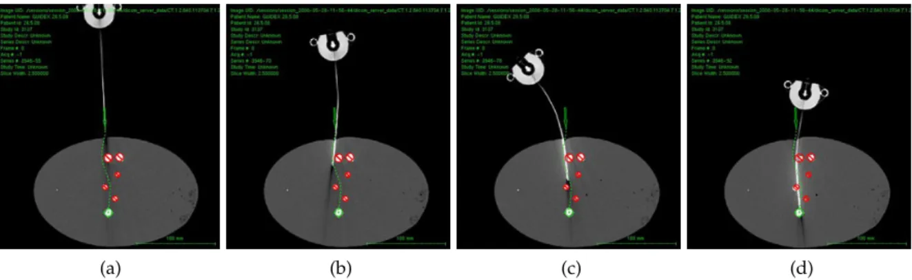
Another possible method for needle steering involves manipulating the base of the needle perpendicular to the insertion direction (DiMaio & Salcudean,2003a; Glozman & Shoham, 2007, 2004). The perpendicular motion causes the entire needle shaft to move inside the tissue like a beam inside a compliant fulcrum (Reed et al.,2011). The insertion point acts as the fulcrum, and once the needle is inserted sufficiently far inside the tissue, the base motion causes the needle tip to move roughly in the opposite direction (see Fig. 1.4).
1.2 Robot-assisted needle steering 11
(a) (b) (c) (d)
Figure1.4: Sequence of CT images during a needle insertion with base manipulation steering
(courtesy of Guide-X Ltd.).
1.1.3 Tissue manipulation
Instead of manipulating the needle to reach a target and avoid obstacles, it is possible to manipulate the tissue in order to move the targets into the needle path or to push obstacles away. Such strategy is often used by physicians which perform it manually, especially in breast biopsy. Inspired by this, recent works have shown that a robotic system can be used to perform image-guided tissue manipulation using blunt-end effectors to achieve the same results in both experiments (Mallapragada et al.,2008; Mallapragada & Sarkar, 2009) and more complex scenarios in simulation (Torabi et al., 2009; Smolen & Patriciu, 2009).
Even though it may be challenging to develop practical mechanisms for deep subsurface targets, robot-assisted tissue manipulation could be used combined with the previously described steering techniques to improve procedure accuracy and target accessibility.
1.2 robot-assisted needle steering
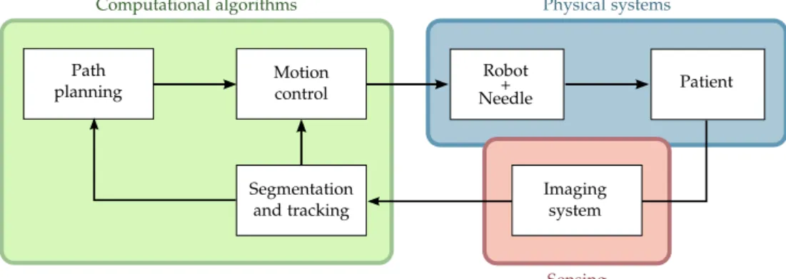
As previously discussed in the Introduction chapter, robot-assisted needle insertion has been an area of active research in recent years to overcome some of the shortcomings of manual needle insertion. Experiments carried out by different groups have shown that a robotic system can insert needles with consistent precision and enables needle steering to obtain complex trajectories inside the body. A robotic device can also be integrated with medical imaging to combine preoperative models and intraoperative images, cutting down procedure times and resulting in an image-guided system that provides timely and accurate feedback about the patient and the intervention.
Path planning
Robot
Patient
Segmentation and tracking
Motion
control Needle+
Physical systems Computational algorithms
Imaging system
Sensing
Figure1.5: Physical systems (blue) and computational algorithms (green) that integrate an
image-guided robotically assisted needle steering system. (Adapted from Cowan et al.,2011).
path planning, motion control, and imaging processing. Each one is described in detail as follows.
1.2.1 Needle steering motion planning
In percutaneous therapy, it is essential to correctly place the medical device in order to have an effective treatment. For this reason, preoperative planning is normally the first step of a needle steering procedure. For steerable needles, this planning is often beyond the capabilities of human intuition due to the complex kinematics and the effects of tissue deformation, tissue inhomogeneities, and other causes of motion uncertainty. To allow the full potential of needle steering, automatic methods have been developed to help clinicians plan paths and needle motion.
Planning can be used purely preoperatively to generate a plan which will be followed during the procedure by the robot or the physician; or intraoperatively by updating the plan online based on intraoperative images or sensor feedback.
1.2.1.1 Deformable tissue planning
The insertion of a needle into soft tissue causes interaction forces between them that result in deformation. Computer simulations that model such forces can be used in pre-operative planning to estimate the deformation behavior and optimize paths for needle insertion procedures.
Alterovitz et al. (2005a) used a2D mesh combined with numerical optimization to com-pute soft tissue deformations and find a locally optimal path for beveled needle insertions. Based in a similar mesh approach, Chentanez et al. (2009) proposed a 3D needle-tissue simulator aiming at surgical planning for a wide variety of needles. This strategy has also been used by Vancamberg et al. (2010,2011) to minimize the final error of a Rapidly-exploring Random Trees (RRT) solution in a breast biopsy application.
1.2 Robot-assisted needle steering 13
forFEMmeshing is quite challenging. Normally, planners that use finite element methods need several minutes to compute a feasible solution, being more suitable for preoperative planning.
If we specifically consider the base manipulation technique, tissue deformation is es-sential to obtain needle steerability and should be carefully considered in the planning and control. DiMaio & Salcudean (2003a) introduced a FEM simulation to estimate defor-mations for tissue and flexible symmetric-tip needles. This method was combined with a numerically obtained manipulation Jacobian and a potential-field-based path planner for planning needle base motion (DiMaio & Salcudean,2005b). Because of its long computa-tion time, the method was designed for offline planning only. Glozman & Shoham (2004) accelerated it by approximating the tissue with a spring model to compute local, instead of global, deformations and thus, enabling fast online planning.
1.2.1.2 Kinematic planning
In the beveled needle insertion technique, one may consider that no significant tissue deformation occurs, and only the needle deforms according to a known kinematic model. Many path planning methods based on the kinematic model of beveled needles have already been proposed in the literature. The first work was that of Park et al. (2005), who introduced a diffusion based approach that considers obstacle-free3D environments. Later, Duindam et al. (2008a) proposed a 3D method for needle path planning which objective is represented numerically as the minimization of a cost function that jointly ex-presses various objectives: deviation of the final needle tip position from the goal location, required control effort, path length and cost associated with penetration of obstacles.
A different solution to the3D motion planning problem is presented by Duindam et al. (2008b, 2010), where instead of optimizing a cost function, they used explicit geometric inverse kinematics for2D and3D needle motion planning. Xu et al. (2008) were the first to apply RRT-based methods to steerable needle planning and more recently, Lobaton et al. (2011) presented a sampling-based method for planning trajectories with multiple goals. However, none of these methods deal with motion uncertainty caused by modeling approximations, tissue deformation and other interaction forces that may cause the needle to greatly deviate from its planned path.
To tackle the uncertainty issue, Alterovitz et al. (2005a;2007) considered uncertainty in needle motion by formulating the planning problem as a Markov Decision Process (MDP) using a discretization of the state space, and a Stochastic Roadmap, respectively. In a more recent work (2008), they presented an approach similar to that of (2005a), but adapted to image-guided procedures. Unlike the previous method, in this work they maximize the probability of reaching the target based on parameters that can be extracted from medical imaging without requiring user-specific cost parameters that may be difficult to determinate.
(a) (b) (c)
Figure1.6: Most common imaging modalities for needle detection:(a)fluoroscopic image showing
a needle steered into ex vivo liver (courtesy of Johns Hopkins University); (b) MRI
image with arrow pointing to a needle artifact (courtesy of Harvard University) ; (c)
ultrasound image with arrow pointing to a needle tip (courtesy of Technion).
1.2.2 Automatic needle tracking in medical images
Automated detection and tracking of the needle make it possible to provide enhanced navigational cues to the clinician or to employ image-based servoing to perform certain tasks of the procedure using medical robotics. Accurate and up-to-date knowledge of the needle position during the insertion is essential to guide the needle and to confirm if the needle tip is at the expected location. Many different medical imaging modalities can be combined with robot-assisted systems for enhancing the performance of automatic needle insertion as discussed below.
Fluoroscopy and CT
Metal needles have high density and tend to be visible in X-ray images such as CT and fluoroscopy. Such images, can be used to localize and reconstruct a needle in 3D when combined with some prior knowledge about the shaft curve (Heibel et al., 2010). A difficulty in using fluoroscopy is that the device must be precisely calibrated, including the relative pose of the fluoroscopy images (Cowan et al., 2011). In CT imaging there is a trade-off between image quality, frame rate and X-ray dose. Modern CT scanners provide short acquisition time with reasonably low radiation dose which is convenient for intermittent observation of the needle and are also able to produce multiple slices for 3D reconstruction.
However, an universal problem of both X-ray based modalities is the exposition to radi-ation. To avoid risks to the human operator, the image acquisition is manually triggered which is a time consuming process and subject to errors. Also, to protect the patient, the X-ray dose should be the minimum possible.
1.2 Robot-assisted needle steering 15
now, most of the reported works on robot-assisted needle steering have used this imaging modality only for confirming the final needle placement (Li et al.,2009; Ding et al.,2008).
MRI
The advantage of MRI over X-ray imaging is the absence of harmful radiation. However, there it requires a compromise between resolution and acquisition rate—intraoperative imaging tends to use much lower resolution than diagnostic images, and the acquisition is usually not real-time. Another disadvantage of MRI, is that metal needles create a large signal void in the image, requiring cumbersome artifact localization (Song et al., 2011) or the use of MRI-compatible needles and robotic devices which do not interfere in the magnetic field (Su et al.,2011; Park & Elayaperumal,2010).
Robotic assistance has already been investigated for automatic insertion of rigid needles under MRI guidance in some medical applications such as transperineal intra-prostatic needle placement (DiMaio et al.,2004,2006), breast biopsy (Fischer & Kutter,2004), and transrectal prostate biopsy (Krieger et al.,2005). Its use for robot-assisted needle steering can also be considered.
Ultrasound
The main drawback of ultrasound is a lower spatial resolution when compared to CT and MRI, and a tendency of US images to be noisy due to reflections, reverberations, shadows, air pockets, and biological speckle, which makes needle localization challenging. It also causes some degree of tissue deformation and dislocation as the transducer makes contact with the tissue scanned.
However, ultrasound imaging has a number of advantages—it is relatively inexpensive and compact, does not involve any ionizing radiation, and does not impose significant ma-terials constraints on the needle and robot design. It also provides real-time information related to tissue properties, target displacement and tool position. Thanks to that, many studies have been conducted regarding needle localization methods in both2D (Okazawa et al.,2006) and3D (Ren et al.,2011) ultrasound images, automatic detection of anatomic structures for anesthesia (Tran & Rohling,2010), and studies on needle-tissue interaction from ultrasound data (Dehghan et al., 2007). Also, it is one of the preferred imaging modalities for robot-assisted needle insertion, with systems developed for conventional insertions with rigid needles (Bassan et al.,2007; Hong et al.,2004) and for needle steering with base manipulation (Neubach & Shoham,2010).
1.2.3 Image-guided control of steerable needles
At the best of our knowledge, the first steering system to integrate planning and con-trol for automatic closed-loop correction of the needle trajectory was that of Glozman & Shoham (2007), which uses the needle base manipulation strategy combined with fluo-roscopic image feedback. In this work, they proposed an inverse kinematics approach to calculate the desired motion of the needle base that would make the tip follow a de-sired trajectory. A similar approach was later used by Neubach & Shoham (2010) with ultrasound guidance.
For the case of beveled needle steering, Kallem & Cowan (2007,2009) proposed a low-level image-based asymptotic controller to stabilize the needle to a desired2D plane. Their non-linear controller only actuates a subset of the needle Degree of Freedom (DOF)’s and has been designed to enforce the plane constraint of2D insertions while working in paral-lel with other higher-level controllers responsible for needle navigation. To deal with the rotation lag between the base and the needle tip caused by torsional stiffness, Reed et al. (2009) have developed a torsion compensator that estimates and controls beveled needles using a mechanics-based model of the rotational dynamics of the needle interacting with the tissue during insertion.
Finally, Reed et al. (2008, 2011) presented a functional steering system that integrates patient-specific 2D pre- and intraoperative planning (Alterovitz & Goldberg, 2007) to-gether with a planar controller (Kallem & Cowan,2007) and torsion compensation (Reed et al., 2009). However, their system requires a dedicated two-DOF device, and the use of intraoperative planning is only suitable for static workspaces since it relies on a roadmap constructed preoperatively.
Some recent works proposed the use of trajectory tracking to follow precalculated paths; for instance, Wood et al. (2010a,b) used a dedicated two-DOF device combined with image feedback to perform trajectory tracking. Ko & Rodriguez y Baena (2012) have proposed another controller for trajectory tracking based on Model Predictive Control (MPC). In both cases, since the controllers do not perform trajectory update, changes in the workspace are not taken into account during the needle insertion.
An alternative to trajectory tracking controllers is the use of intraoperative path plan-ners in order to perform online trajectory update from image feedback information. Hauser et al. (2009) were the first to use this kind of control-loop policy for needle steering. How-ever, only obstacle free environments were considered.
1.3 conclusions
1.3 Conclusions 17
Next, we discussed the use of image-guided robot-assisted systems and presented the state of the art in steerable needle technologies, together with the main challenges of this kind of procedure. Patient motion and physiological changes between preoperative planning and treatment phases are known causes of inaccuracy in percutaneous therapies. Also, the presence of uncertainties due to tissue deformation, tissue inhomogeneity, posi-tioning errors and other modeling approximations often cause the needle to deviate from the original plan. Motivated by this, we propose a closed-loop strategy for needle steering that considers dynamic workspaces and disturbances in the expected needle motion.
2
N E E D L E M O D E L I N G
In Chapter1, we examined the main needle steering approaches and how the interaction forces between the needle and the tissue affect the needle trajectory and the position of anatomical structures inside soft tissue. We also presented the concept of robot-assisted needle steering systems and their main computational modules. For robotically steered needles, an analytical model that predicts tissue deformation and needle deflection is desirable for optimization of the system design, path planning, and real-time control.
In order to model the effects of needle-tissue interaction, the relation between the locally applied force and motion of both tissue and needle have to be measured. However, there is no way to measure the local force directly since force sensors can only detect the force at their attached point. Also, during insertion, the needle punctures and passes through different tissue layers and membranes, varying interaction forces in the tip during each stage. Forces also change with needle depth and angle of insertion and for the same type of tissue, they even vary due to patient specific characteristics. The modeling of such effects is especially complex because of the inhomogeneous, nonlinear, anisotropic, elastic and viscous behavior of soft tissue (Abolhassani et al.,2007) and it has been a subject of much research.
A general survey on tool and tissue interaction models which describes both physics-and non-physics based interaction models is provided by Misra et al. (2008a). However, most of the presented studies are not specific to needle interaction and all of them focus on the description of tissue deformation, disregarding the interaction effects on the tool itself. In this chapter, we present some results from the literature that are more specific to needle insertion modeling. Also, we introduce the nonholonomic kinematic model adopted in this thesis and present some of the possible insertion techniques that have been developed for the steering of beveled needles in2D and3D.
2.1 needle insertion forces
It is important to understand the forces that act during the insertion of a needle into soft tissue because they can help to identify and model different tissue types and provide feedback for robot-assisted systems. However, when measuring needle insertion forces, only the resultant force acting at the proximal end of the needle is available, while in fact penetration forces are distributed along the entire length of the needle axis, resulting from physical phenomena such as cutting, elastic deformation and friction. The measured needle insertion force is actually the integration of such force distribution along the needle shaft.
DiMaio & Salcudean (2002, 2003a, 2005a) performed pioneering work in needle inser-tion modeling and simulainser-tion. They proposed a methodology for estimating the force distribution that occurs along the needle shaft by exploring the relationship between nee-dle forces and2D tissue deformation. It was based on a linear elastostatic material model, discretized using the FEM to derive contact force information that is not directly
(a) A force is applied at the boundary of a deformable body and the resultant tissue deformation is observed.
Force per unit length
Penetration depth
(b) Needle force distribution for a 1mm/s
in-sertion: constant along the needle shaft and higher at the tip because of tissue cutting.
Figure2.1: DiMaio and Salcudean’s modeling of needle insertion is based in:(a)the observation of
2D tissue deformation, and(b)correspondent force distribution along the needle shaft.
(Adapted from DiMaio & Salcudean,2005a).
surable. The obtained force distribution indicated the existence of two forces: an axial friction force between the needle and the tissue, which is uniform along the shaft, and a force peak at the needle tip, which results from the cutting of the tissue as illustrated in Fig. 2.1b.
The work done by Simone & Okamura (2002) modeled such forces from experimental ex vivo studies conducted on bovine liver. They divided the needle insertion process in pre- and post- puncture of the organ membrane. During pre-puncture, we have the pres-ence of stiffness forces due to the elastic properties of the organ, which were modeled as a nonlinear spring with elastic constant obtained by curve fitting the experimental data. As the insertion proceeds, the force value rises steadily until a sharp drop indicates the rup-ture of the liver membrane. During post-puncrup-ture, friction and cutting forces are added to the pre-puncture stiffness force. A modified Karnopp friction model which includes both the static and dynamic friction coefficients was used to model the friction during needle insertion. Finally, the cutting forces were obtained by subtracting the puncture and friction force from the total measured force.
Maurin et al. (2004) studied the forces involved duringin vivopercutaneous procedures into liver and kidney of anesthetized pigs. Their experimental data was fitted to Simone and Okamura’s model and to a second-order polynomial model taken from Maurel (1999), with low errors for both models. Their results also confirmed the increase in insertion forces during membrane punctures. Kataoka et al. (2002) investigated needle deflections with the insertion of a needle with triangular pyramid tip into a canine prostate while measuring the insertion force. By using a needle consisting of an outer and inner part, they were able to separately measure shaft forces and tip forces during needle insertion.
2.2 Needle deformation 21
↵ ↵
(a) Symmetric needle tip
↵
(b) Asymmetric (beveled) needle tip.
Figure2.2: Interaction forces at the needle tip when inserted into homogeneous soft tissue. The
black arrows indicate the tissue compression reaction forces while the red arrow is the resultant direction of tissue cutting. The asymmetry of the bevel produces a resultant transverse load which causes the needle to naturally bend when inserted into soft tissue. (Adapted from Misra et al.,2010).
an element subdivision approach to ameliorate the effects of added computational com-plexity. Their work considered homogeneous models and rigid needles, neglecting again the effects of needle deflection.
2.2 needle deformation
During the insertion of a needle, the tissue around the tip deforms due to compression, and it imposes a reaction force contrary to this compression as shown in Fig. 2.2. In the case of a perfectly symmetric-tip needle being inserted into homogeneous tissue, such forces are equally distributed in all directions and the cut of tissue occurs in the insertion direction. However, when there is an imbalance in the forces distribution due to changes in the mechanical properties of the material into which the needle is inserted, or because of an asymmetric geometry of the tip, the tissue cut happens at an offset angle which depends on the tip geometry, needle flexibility and tissue properties.
In recent works, a lot of effort has been put in the modeling of needle deformation. Some studies propose methods for estimating the tip motion based on fundamental me-chanical and geometrical properties of the needle and tissue, while other approaches use empirical observations of each needle and tissue combination in order to fit model param-eters. Both techniques are discussed in more detail as follows.
2.2.1 Mechanics-based models
Tissue
Pinput
r
C10
Gc µ
α E,I
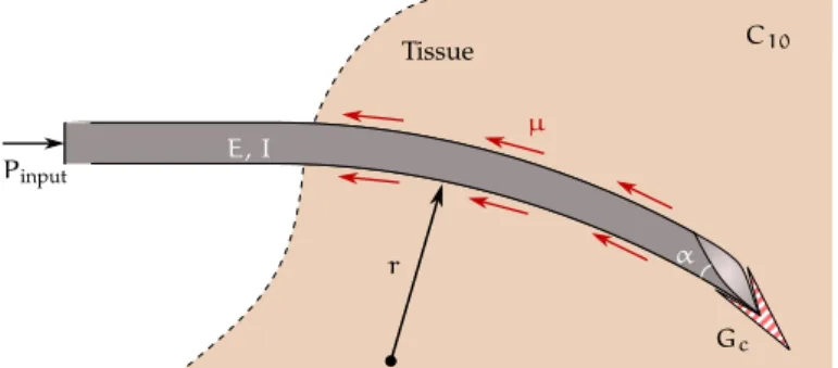
Figure2.3: Schematic of a beveled needle interacting with soft elastic medium. The model
incor-porates the tip bevel angle (↵), the needle’s Young’s modulus (E), and second moment
of inertia (I); the tissue’s nonlinear hyperelastic material property (C10), rupture
tough-ness (Gc), and coefficient of friction (µ); and the input displacement from the robot
(Pinput). (Adapted from Misra et al.,2009).
Okamura et al. (2004) analyzed the effects of needle diameter and tip type on needle deflection. Tests were performed on ex vivo bovine liver and silicone rubber phantoms and confirmed that the size and shape of the needle play an important role in determining both the forces of the needle insertion and the amount of needle deformation. Their work concluded that smaller needle diameters lead to less resistance force but more needle bending, and the use of beveled needles also results in more bending when compared to cone and triangular tips.
The effects of insertion velocity and tip bevel angle were analyzed by Webster III et al. (2005), who performed needle insertions into a relatively stiff phantom. Their results showed that decreasing the bevel angle increases the amount of needle deflection, but the bevel angle has little impact on the amount of axial force. They also found that the velocity of needle insertion in a stiff phantom had no significant effect on the amount of needle deflection, while it did change the amount of the axial force.
A study on the effect of needle shape and tissue material on tip forces and needle de-flection has been presented by Misra et al. (2008b). They performed experimental studies on phantom and real tissues in order to obtain their elasticity and toughness parameters. These tissue properties were incorporated in a finite element simulation to show the rela-tionship between needle bevel angle and the forces generated at the tip. The interaction of the needle tip deforming and rupturing tissue has been modeled with both contact and cohesive zone models. In general, it has been observed that tip forces were sensitive to the rupture toughness and that smaller bevel angles resulted in larger axial and transverse tip forces. Also, for most applications in which the needle would be steered through soft tissue, large variations in tissue elasticity are not expected.
2.2 Needle deformation 23
Tissue
y
k1
ki
kn
x - element number
1 i n
1
Figure2.4: System model as a flexible beam subject to a number of virtual springs. (Adapted from
Glozman & Shoham,2007).
and the inclusion of an energy term to represent friction dissipation still has to be investi-gated in future studies.
2.2.2 Phenomenological models
Instead of using mechanical analysis, some models are based in phenomenological ob-servation of needle and tissue interactions, that is, they try to fit data obtained with experiments to parametric models.
Considering the case of base manipulation—when the needle is stiff relative to the tissue—two models that relate the motions at the needle base to motions at the tip have already been proposed. In Glozman & Shoham (2007), the needle kinematic model is derived by modeling the soft tissue as springs with stiffness coefficients that vary along the length of the needle. In this approach, the needle is approximated by a linear beam subjected to point forces applied by the deformed tissue and modeled as virtual springs (see Fig. 2.4). Images are used to track the needle and detect its shape. The beam is split into many small elements and its displacements are used to calculate spring forces using finite-elements theory. From virtual spring forces applied to each element, they obtain the kinematic model of the needle. The resultant inverse kinematics is then used to determine the needle trajectory from motions applied at its base.
The second model from DiMaio & Salcudean (2003b, 2005b) involves numerically cal-culating the tissue Jacobian which is the matrix that relates the derivatives of needle base and needle tip configurations, as depicted in Fig. 2.5. Using this relation, the tip veloci-ties can be determinated from the velocity of the needle base, and consequently, one may obtain the current needle tip position.
For the case of flexible beveled needles inserted in relatively hard tissues, Webster III et al. (2006a) have developed a kinematic model for needle steering. In contrast to the previously presented approaches (Glozman & Shoham,2007; DiMaio & Salcudean,2003b, 2005b), in this case there is no significant tissue displacement during needle insertion. Thus, they consider that only the needle deforms, and its deflection is caused by asym-metric forces applied on the beveled tip. As the needle is inserted into the tissue, the tissue imposes a reaction force on the bevel that deflects the needle tip.
ef-Obase Otip ✓base ✓tip 2 6 6 4 ˙xtip ˙ytip ˙ ✓tip 3 7 7 5
=J(qk)
2 6 6 4 ˙xbase ˙ybase ˙ ✓base 3 7 7 5 ytip xtip xbase ybase
Figure2.5: Motion of the needle tip with respect to the motion applied to the needle base. The
tissue Jacobian matrix Jq depends on the current needle tip configuration given by
q= [ xtip ytip ✓tip ]T. (Adapted from DiMaio & Salcudean,2005b).
fect of a duty-cycled rotation applied around the needle shaft, initially proposed by Engh et al. (2006a,b). The spinning is used during needle insertion in order to vary the needle path curvature—when the needle is inserted with constant spinning at a rate relatively larger than the insertion velocity, straight trajectories can be achieved. By alternating spin-ning and non-spinspin-ning periods, different curvature values can be achieved with the same needle-tissue combination.
It is still an open question whether mechanics-based, non-physics-based, or some com-bination of these is the best method for modeling needle-tissue interaction in real time. The development of models that can appropriately and accurately describe needle inser-tions whilst being computationally efficient remains as a research challenge.
Although mechanics-based models are capable of providing a fundamental understand-ing of needle-tissue interaction mechanics, they normally require prior knowledge of many geometrical and mechanical properties of the needle and tissue materials, mea-surement of applied torques and forces, and sometimes, even the numerical computation of finite element meshes which can be quite demanding.
On the other side, phenomenological models were primarily design to enable real time use. Even though accurate physics is not deemed a priority in such models, the results presented in the literature have demonstrated that they are able to capture needle-tissue behavior with sufficient accuracy to be used in planning and control. Thus, for modeling the flexible beveled needle behavior, we adopted the kinematic model developed by Web-ster III et al. (2006a) and its duty-cycled variation proposed by Minhas et al. (2007). For convenience, we adapted the mathematical formulation, which was originally presented in Lie algebra, to Clifford algebra. The resultant model is described and presented as follows.
2.3 beveled needle kinematic model