Alternative materials infiltration in 3D ceramic models
printed by Binder Jetting: a feasibility assessment
Edwin Marcelo Ocaña Garzón
Edwin Marcelo Ocaña Garzón
Thesis submitted to the Faculty of Engineering of the University of Porto - FEUP in partial fulfilment of the requirements for the degree of
Doctor in Mechanical Engineering
Advisor: Jorge Lino Alves, PhD
Associate Professor at FEUP
Department of Mechanical Engineering (DEMec) Doctoral Program in Mechanical Engineering (PRODEM)
Faculty of Engineering of the University of Porto (FEUP) Porto, July 2019
vii
and sincerely grateful.
First of all, I am deeply grateful to my Father God, who has always remained at my side, putting angels on my path to get me up every time I fell, and has given me opportunities and privileges in life.
To my parents, Mauro and Rosa, to whom I dedicate all I have obtained, because they gave me everything with so much sacrifice. From them I received the best teachings of life from my first days, leaving me their legacy, honesty, the value of the simple things of life and supporting me at all times also making me know that I always count on them.
To my children, Belén, Sofia and José Daniel, for their motivation and joy that they give me every day with a simple smile, a word and their sweetness encouraging me to take on new challenges and overcome even the most difficult ones.
To my wife, Margoth, who patiently endured and supported me in the good and hard times.
To my brothers Hernán and Nancy who have always sought my personal advancement with their advice and support.
To all my family, of whom I am proud, who are wonderful, namely my grandparents who have been exemplary. All of them have given me their support when it has been necessary.
To my advisor, Professor Jorge Lino, who has trusted me and gave me the opportunity to successfully complete my PhD.
To Carlos Naranjo, and other colleague professors from Universidad de las Fuerzas Armadas-ESPE, who trusted and supported me to obtain the funding to study this doctorate.
To Leonardo Santana, a real friend in and out of the University, who with his sincerity and advice gained my trust and friendship, being also a key support to successfully complete this work.
To Beatriz Graça, Carla Monteiro and Susana Sousa, staff from FEUP, at one time or another, supported me academically with great collaboration.
To Aurelio Netto, Professor of the Instituto Federal de Educação, Ciência e Tecnologia de Santa Catarina- IFSC, who disinterestedly contributed with his time to structure this work.
viii
Finally, to all of those who directly or indirectly contributed to this thesis, and have not been mentioned for a lapse of memory.
“Trust in the Lord with all your heart, and lean not on your own understanding” (Proverbs 3:5-NIV)
July, 2019 Edwin Ocaña Garzón
ix
This research is supported by the: Universidad de las Fuerzas Armadas ESPE, Ecuador under grant – Orden de rectorado Nº 2014-299-ESPE-a-3, and Project NORTE-01-0145-FEDER-000022 - SciTech - Science and Technology for Competitive and Sustainable Industries, cofinanced by Programa Operacional Regional do Norte (NORTE2020), through Fundo Europeu de Desenvolvimento Regional (FEDER).
xi
powder-base materials, is the low mechanical strength of green three-dimensional printed (3DP) components. In order to overcome this disadvantage, post-processing (PP) operations are required, being the infiltration with polymeric materials the mostly used technique. The scarcely available literature, plus the limited infiltrating materials accessible to all types of users, make this stage an arduous task and strongly dependent on solutions offered by BJ technology providers, which are generally higher cost. Based on these limitations, the opportunity to develop a doctoral research was presented with the aim of providing tools to better understand the steps of printing and infiltration, as well as the selection and adequate application of alternative infiltrating materials (not necessarily dedicated to infiltration of 3DP parts), aiming to improve the flexural properties of 3DP models, with simple and fast procedures. For this purpose, the study was divided into five stages: i) characterization of the printing powder, ii) evaluation of 3DP parts in their green condition, iii) thermal and mechanical analysis of 3DP models infiltrated with methods and materials suggested by the supplier of the technology BJ, iv) selection (based on technical, economic and accessibility criteria), characterization and infiltration of 3DP samples with alternative infiltrants, and v) cure improvement (time and flexural properties) of the material with grater challenges to infiltration process, identified in the previous study. Among the main characterizations used, the chemical composition, morphology, particle size distribution, permeability measurement, hydraulic conductivity, pore size distribution, thermal analysis, and mechanical (static and dynamic) tests are highlighted. The obtained results demonstrate the possibility of using alternative infiltrating materials, different of those suggested by the supplier of the technology, thus offering a viable set of solutions to reduce post-processing times and costs, while also improving the mechanical properties of infiltrated 3DP models. More generally, this research contributes to re-stimulate and disseminate scientific studies in the field of BJ technology.
Keywords: 3D Printing, Binder Jetting, plaster powder, infiltration, alternative infiltrants, epoxy resin, flexural properties.
xii
Uma das maiores limitações associadas à tecnologia Binder Jetting (BJ), com materiais à base de pó de gesso, é a baixa resistência mecânica em verde dos componentes impressos tridimensionalmente (3DP). Para superar esta desvantagem, são necessárias operações de pós-processamento (PP), sendo a técnica de infiltração com materiais poliméricos a mais utilizada. A pouca difusão literária, e a restrita quantidade de materiais infiltrantes disponíveis e ao alcance de todo o tipo de utilizadores, tornam esta etapa uma tarefa árdua e fortemente dependente de soluções oferecidas pelos fornecedores da tecnologia BJ, que são geralmente de maior custo. Baseado nestas limitações, verificou-se a oportunidade de se desenvolver uma investigação de doutoramento com o objetivo de fornecer ferramentas para aumentar a compreensão das etapas de impressão e infiltração, além da seleção e aplicação adequada de materiais infiltrantes alternativos (não necessariamente dedicados à infiltração de peças 3DP) visando melhorar as propriedades mecânicas à flexão de modelos 3DP, com procedimentos simples e rápidos. Para tal, o estudo foi dividido em cinco etapas: i) caracterização do pó de impressão, ii) avaliação das peças 3DP na sua condição em verde, iii) análise térmica e mecânica de modelos 3DP infiltrados com métodos e materiais sugeridos pelo fornecedor da tecnologia BJ, iv) seleção (com base em critérios técnicos, económicos, e de acessibilidade), caracterização, e infiltração de amostras 3DP com infiltrantes alternativos, e v) melhoramento da cura (tempo e propriedades à flexão) do material com maiores desafios ao processo de infiltração, identificado no estudo anterior. Entre as principais caracterizações utilizadas ao longo das etapas mencionadas, destacam-se: composição química, morfologia, distribuição de tamanho de partícula, medição da permeabilidade, condutividade hidráulica, distribuição do tamanho de poro, análises térmicas, e ensaios mecânicos (estáticos e dinâmicos). Os resultados obtidos demostram a possibilidade de se utilizar materiais infiltrantes alternativos aos sugeridos pelo fornecedor da tecnologia, oferecendo assim um conjunto de soluções viáveis para reduzir os tempos e custos de pós-procesamento, e melhorar as propriedades mecânicas à flexão dos modelos 3DP infiltrados. De um modo mais geral, esta investigação contribui para reimpulsionar e difundir estudos científicos no âmbito da tecnologia BJ.
Palavras-chave: 3D Printing, Binder Jetting, pó de gesso, infiltração, infiltrantes alternativos, resina epóxi, resistencia à flexão.
xiii
1.1 Problem presentation and thesis motivation ... 1
1.2 General aim ... 2
1.3 Specific aims ... 2
1.4 General Methodology ... 3
1.5 Outline of the thesis ... 4
Chapter 2. Characterization of powder material and three-dimensional printing models in the green state ... 7
2.1 Introduction ... 7
2.1.1 Powder and binder materials ... 9
2.1.2 Printing Parameters ... 11
2.2 Materials and 3D Printer ... 15
2.2.1 3D Printing materials ... 15
2.2.2 3D Printer and parameters ... 15
2.3 Characterization of powder and green 3DP model ... 18
2.3.1 Chemical composition and morphological analysis of powder and green 3DP model ... 18
2.3.2 Powder particle size distribution ... 19
2.4 Results and Discussion ... 20
2.4.1 Powder Characterization... 20
2.4.2 Green body printing part characterization ... 24
2.5 Conclusions ... 26
Chapter 3. Infiltration tests to assess the permeability and hydraulic conductivity of 3D printed plaster parts under different conditions ... 27
3.1 Introduction ... 27
3.2 Materials and methods ... 28
3.2.1 Permeameter development and permeability measurement ... 31
3.3 Results and discussions ... 33
3.4 Conclusions ... 38
Chapter 4. Mechanical and thermal characterization of 3DP parts in green state and infiltrated with conventional infiltrants ... 41
4.1 Introduction ... 41
xiv
4.2.3 Waxes ... 43
4.2.4 Parameters of the post-process infiltration ... 44
4.3 Materials and methods ... 47
4.3.1 Sample preparation ... 47
4.3.2 Infiltration process ... 49
4.3.3 Experimental Techniques ... 51
4.4 Results and discussions ... 53
4.4.1 Tensile and bending test ... 53
4.4.2 Infiltrant absorption ... 55
4.4.3 Thermogravimetric analysis and differential scanning calorimetry ... 57
4.5 Conclusions ... 60
Chapter 5. Selection of infiltrants for plaster-based 3DP models, case study and infiltrant cure improvement ... 63
5.1 Introduction ... 63
I. Selection of alternative infiltrants ... 65
5.2 Requirements of potential infiltrants and their selection ... 65
5.3 Alternative infiltrants materials ... 65
5.3.1 Epoxy resins and cyanoacrylates ... 66
5.3.2 Other infiltrant materials ... 68
5.4 Selection and characterization of alternative infiltrant materials ... 70
5.4.1 Selection of infiltrant materials ... 71
5.4.2 Preparation of specimens and resin samples ... 72
5.4.3 Differential Scanning Calorimetry of resins ... 73
5.4.4 Dynamic Mechanical Analysis of resins ... 73
5.4.5 Tensile and bending characterizations ... 74
5.5 Results and discussions ... 75
5.6 Conclusions ... 82
II. Case study: Mechanical properties of 3DP models with different thicknesses infiltrated with alternative materials ... 85
5.7 Introduction ... 85
5.8 Materials and Methods ... 87
5.8.1 Characterization of infiltrants ... 88
5.8.2 Characterization of infiltrated 3DP samples ... 90
5.9 Results and discussions ... 94
xv
III. Improvement of the cure of the epoxy infiltrant (E3) ... 107
5.11 Materials and Methods: ... 109
5.11.1 Experimental Techniques ... 111
5.12 Results and discussions ... 112
5.12.1 Thermogravimetric analysis of resin 𝐸3 ... 112
5.12.2 Differential Scanning Calorimetry of resin 𝐸3 ... 113
5.12.3 Post-cure treatment of 𝐸3 resin. ... 116
5.13 Final considerations ... 118
5.14 Conclusions ... 120
Chapter 6. Conclusions and suggestions for future works ... 123
6.1 Conclusions ... 123
6.2 Recommendations for future work ... 126
References ... 121
Appendices……. ... 133
Appendix 1 Study of the viability of manufacturing ceramic moulds by additive manufacturing for rapid casting ... 141
Appendix 2 Technical data sheet of the resin Strength Max (E1) ... 147
Appendix 3 Technical data sheet of the resin Biresin CR83-6 (E2) ... 151
Appendix 4 Technical data sheet of the resin Elantas EC131LV / W342 (E3)... 155
Appendix 5 Technical data sheet of the resin Crystal Clear 200 (U) ... 159
Appendix 6 Heating and cooling rates (ramps) and conditioning time before bending test for resin cure improvement EC131LV-W342 (E3) ... 161
Appendix 7 Experimental measurement of viscosity vs. temperature of the mixed components of epoxy resin EC131LV-W342 (E3) ... 167
xvii Figure 2. Schematic of Binder Jetting (10) ... 7 Figure 3. Key parameters on Binder Jetting and infiltration process ... 9 Figure 4. Dehydration and calcination of calcium sulphate (adapted from (23)) ... 10 Figure 5. a) Built orientation relative to Z axis (adapted from (35)), and b) view of three built
orientations in 3D Edit Pro 2.0 software (adapted from (36)) ... 12 Figure 6. 3D printer and printing materials with some printed specimens in the cleaning chamber .... 16 Figure 7. 3D printing process methodology ... 17 Figure 8. 3D model for microscopic analysis a) CAD design, and b) green 3DP model ... 19 Figure 9. Overlay particle size distribution of 3D printing VisiJet PXL core® powder, in volume
density (%) ... 21 Figure 10. SEM analysis of large representative particles of VisiJet PXL core® powder... 21
Figure 11. a) Chemical analyses (wt %) of powder particles 1 and 2, and comparison with b) crystals of α-CaSO4·0.5H2O SEM microphotographs (adapted from (56) ... 23
Figure 12. 3D printed green body (centre) and SEM images of mapping 1 (left) and mapping 2 (right) ... 24 Figure 13. SEM images of elemental chemical analysis of a green body specimen and respective
spectrum according to a) mapping 1, b) mapping 2 ... 25 Figure 14. Research methodology to determine the permeability, hydraulic conductivity and porosity
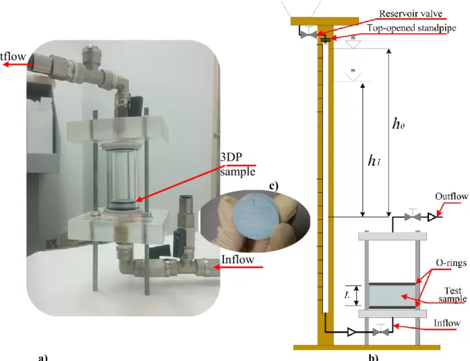
of 3DP parts. ... 29 Figure 15.Configuration and dimensions of saturation binder, a) high saturation "Hs" and b) default
saturation "Ds" for a cubic geometric ... 30 Figure 16. Layout of the 3DP samples in the 3D printer build chamber ... 30 Figure 17. a) Custom-made rigid wall falling head permeameter, b) its scheme and c) 3DP sample... 32 Figure 18. Pareto ANOVA diagram to identify the fitted mean and its standard error of a) hydraulic
conductivity (K), and b) permeability (k) of 3DP samples. The significant factors are highlighted in the yellow square ... 35 Figure 19. Cross section of the 3DP samples mounted on the porosimeter. The fluid passes through
the sample thickness "L" printed with different a) build orientation, and b) binder saturation. The length of the flow path was outlined (in red line) according to the significance found for these factors. ... 36 Figure 20. Intrusion/extrusion cycles into a 3DP sample and pore size analysis (dV/dlog(D) in red
xviii
Figure 23. Cleaning stages: depowdering in the 3D printing chamber with vacuum system for a)
coarse core removal, b) fine core removal and c) depowdering with compressed air gun .... 49
Figure 24. Materials and infiltration methods suggested by technology provider BJ ... 50
Figure 25. Samples infiltrated with a) Epoxy resin (E1) for bending test, and b) Cyanoacrylate (CY) for tensile test ... 50
Figure 26. a) Bending and b) tensile tests of 3DP samples ... 52
Figure 27. a) Maximum flexural strength of infiltrated and not infiltrated 3DP samples vs. manufacturing data, and b) zoom of part a) ... 54
Figure 28. Maximum tensile strength of infiltrated specimens compared with manufacturer data ... 55
Figure 29. Weight of dry infiltrant absorbed by specimens (%) vs. Flexural strength: a) (E1) and (CY), b) (MS), and c) for (W) ... 56
Figure 30. Thermogravimetry of 3DP models infiltrated with water, cyanoacrylate and epoxy resin in air atmosphere ... 58
Figure 31. DSC curves of 3DP specimens infiltrated with water (W), cyanoacrylate (CY), and epoxy resin (E1). ... 59
Figure 32. Test of a) DSC, and b) DMA of cured resin samples E1, E2, E3 and U ... 74
Figure 33. a) Tensile, and b) bending and tests of resin samples ... 75
Figure 34. DSC thermograms of specimens of cured resin (𝐸1, 𝐸2, 𝐸3 and 𝑈) ... 76
Figure 35. Dynamic-mechanical properties of epoxy (𝐸1, 𝐸2, 𝐸3) and urethane (𝑈) resins, a) storage modulus (𝐸′), indicating the values at 40 ºC, and b) loss factor (𝑡𝑎𝑛𝛿). Peaks show the 𝑇𝑔´𝑠 ... 77
Figure 36. Tensile strength (MPa) vs. Young’s modulus (GPa) of 𝐸1, 𝐸2, 𝐸3 and 𝑈 resins compared with other potential infiltrants, supported by (134) ... 79
Figure 37. 3.2 mm thick cross sections of plaster-based 3DP samples infiltrated with black and blue diluted ABS solution. Full immersion for 5, 10 and 150 minutes The clear part shows the non-infiltrated area. ... 81
Figure 38. Flexural strength (MPa) vs. price (€/kg) of 𝐸1, 𝐸2, 𝐸3 and 𝑈 resins compared with other potential infiltrants, supported by (134) ... 81
Figure 39. Diagram of the research stages ... 88
Figure 40. a) Schematic diagram of the vibro-viscometer (adapted from (163)), b) experimental measurement of viscosity (resin 𝐸2) ... 90
Figure 41. Build position and orientation of a batch of samples in the 3D printer chamber ... 92
Figure 42. Simple full immersion method used to infiltrate 3DP samples for flexural test ... 93
xix Figure 45. Pores reduction rate (RP) versus thickness of 3DP infiltrated samples ... 97 Figure 46. Experimental results of; a) fM, and b) B for 3DP infiltrated samples, (averages and
standard deviations) ... 98 Figure 47. ANOVA analysis for RP by resin type and thickness of the samples; a) mean RP for
resins and thickness, b) interaction of the two factors, and c) comparisons by Tukey pairwise, ci=0.95 ... 99 Figure 48. ANOVA analysis for fM by resin type and thickness of the samples; a) means of main
effects (MPa), b) and c) comparisons by Tukey pairwise, (ci=0.95) ... 100 Figure 49. ANOVA analysis for B by resin type and thickness of the samples; a) means of main
effects (GPa), b) their interaction, c) and d) comparisons by Tukey pairwise, (ci =0.95) ... 102 Figure 50. a) Flexural Strength of infiltrated samples and resins, and b) their ratios ... 103 Figure 51. a) Flexural modulus of infiltrated samples and resins, and b) their ratios ... 103 Figure 52. Generalized time-temperature-transformation (TTT) isothermal cure diagram, (adapted
from (99)) ... 108 Figure 53. Thermogravimetry of uncured resin 𝐸3 under inert (𝑁2) and oxidizing (𝑂2) atmospheres
... 112 Figure 54. DSC curves (first scan) of 𝐸3 resin, uncured and submitted to different cure treatments . 114 Figure 55. DSC curves (second scan) of 𝐸3 resin of uncured and subjected to different cure
treatments ... 115 Figure 56. a) flexural strength (𝜎𝑓𝑀) and b) flexural E-modulus (𝐸𝐵) for different cure levels of
resin 𝐸3 ... 117
Figure A 1. Mean effects by factors 𝑅𝑚- 𝐶𝑇 for a) flexural strength 𝜎𝑓𝑀, and b) the E-modulus 𝐸𝐵 ... 163 Figure A 2. Time-temperature data in the curing oven for isothermal cure level 𝑁1 = 140 ºC, with
heating and cooling ramps for a) 𝑅𝑚, and b) 𝑅𝑓... 164 Figure A 3. Flexural strength 𝜎𝑓𝑀 and the E-modulus 𝐸𝐵 for the combination of 𝑅𝑚, 𝑅𝑓 and 𝐶𝑇
factors ... 165 Figure A 4. Temperature of the mixed components of epoxy resin EC131LV-W342 (𝐸3) ... 167
xxi
Table 2. Powder characteristics and the influence on printing (adapted from (15)) ... 10
Table 3. Previous studies on the influence of different parameters in BJ green parts in plaster based materials ... 12
Table 4. Default printing parameters selected ... 17
Table 5. Parameters for particle size analysis of powder by Laser Diffraction (wet and dry conditions) ... 20
Table 6. Chemical composition (wt%) of the 3DP model and plaster powder particles (all certainties are 0.96-1.00) ... 25
Table 7. DoE with factors and levels for 3DP permeability test samples. ... 28
Table 8. Experimental results of hydraulic conductivity-K, permeability-k, and apparent porosity-𝜙𝑜 for L16 orthogonal array sample, measured by falling head permeameter and saturation methods. ... 34
Table 9. Samples permeability (𝑘𝐻𝑔) and apparent porosity (𝜙𝐻𝑔), measured by Mercury Intrusion Porosimetry method, and apparent porosity (𝜙𝑜) ... 37
Table 10. Previous studies of influential parameters in infiltrated plaster-based 3DP parts ... 45
Table 11. Methods and main infiltration parameters ... 49
Table 12. Endothermic peaks found in thermogravimetric analysis (TGA) of infiltrated 3DP samples ... 57
Table 13. Exothermic temperature, and endothermic phases for 3DP samples infiltrated with W, CY and E1 ... 59
Table 14. Physical, mechanical and thermal data of 2-cyanoacrylate (130) ... 68
Table 15. Main physical data of the infiltrants, adapted from (108, 149-151) ... 72
Table 16. Experimental conditions for cure and post-cure... 73
Table 17. Exothermic peak temperatures (𝑇𝑔 𝐷𝑆𝐶 ) and energy released by the cured resin samples ... 76
Table 18. Glass transition temperatures (𝑇𝑔 𝐷𝑀𝐴 ), useful operating temperature range and storage modulus 𝐸′ of cured resin samples obtained in DMA test ... 78
Table 19. Average values and standard deviation of tensile and bending tests of cured resins 𝐸1, 𝐸2, 𝐸3 and 𝑈 ... 79
Table 20. Studies of plaster-based 3DP parts infiltrated with not dedicated infiltrants ... 86
Table 21. Factors and assigned levels for DoE of 3DP samples ... 91
xxii
Table 25. Viscosity, flexural strength and flexural modulus of epoxy resins, average with standard deviation and coefficient of variation (%) ... 96 Table 26. Experimental results of mass measurements, RP, fM, and B of 3DP infiltrated samples
(average and standard deviation for each condition) ... 97 Table 27. ANOVA of porous reduction rate (RP) vs. resin and thickness of the sample (ci = 95%) ... 98 Table 28. ANOVA of Flexural Strength "fM " vs. resin and thickness of the sample (ci = 95%) ... 100 Table 29. ANOVA of flexural Modulus “B” vs. resin and thickness of the sample (ci = 95%) ... 101 Table 30. Ratios (3DP models over resins) of flexural strength and flexural E-modulus ... 104 Table 31. Pre-selected variables for the analysis of curing time and temperature conditions... 110 Table 32. levels of cure time-temperatures proposed to study ... 111 Table 33. Levels of the control variables in post-cure conditions ... 111 Table 34. Exothermic peak temperatures and energy released by the samples during post-cure
treatments. ... 114 Table 35. Glass transition temperatures obtained with post-cure treatments. ... 115 Table 36. Average and standard deviation of flexural strength (𝜎𝑓𝑀) and flexural E-modulus (𝐸𝐵)
for different cure levels of resin 𝐸3 ... 116 Table 37. Viscosity and bending properties of 𝐸3 resin compared to reference resin 𝐸1 ... 117 Table 38. Analogy of 𝜎𝑓𝑀 of infiltrated 3DP parts when they are infiltrated with resins E1 at RT,
and E3 at 40ºC. ... 119 Table 39. Maximum flexural strength achieved in plaster-based 3DP parts with infiltrants of
different viscosities ... 120
Table A 1. Initial ramps and conditioning time before bending test ... 161 Table A 2. Flexural strength 𝜎𝑓𝑀 and the E-modulus 𝐸𝐵 for the combination of 𝑅𝑚- 𝐶𝑇 factors ... 162 Table A 3. Analysis of variance for flexural strength 𝜎𝑓𝑀 versus 𝑅𝑚 and 𝐶𝑇 ... 162 Table A 4. Analysis of variance for E-modulus 𝐸𝐵 versus 𝑅𝑚 and 𝐶𝑇 ... 163 Table A 5. Flexural strength 𝜎𝑓𝑀 and the E-modulus 𝐸𝐵 for the combination of 𝑅𝑓- 𝐶𝑇 factors .... 164
xxiii
k permeability
K hydraulic conductivity
Ks saturated hydraulic conductivity
𝜙𝑜 apparent porosity measured by saturated liquid technique
Lv low viscosity
Hv high viscosity
Do default print orientation Vo vertical print orientation
Ds default saturation level of binder/volume ratio Hs high saturation level of binder/volume ratio
Cl colour binder
nCl colourless binder
ℎ0 initial fluid level
ℎ1 final fluid level
L length of porous sample
A cross-sectional area of porous specimen
t time
fluid dynamic viscosity (or absolute)
fluid density
g gravity acceleration
𝑚𝑑 weight in dry state
𝑚𝑠𝑢𝑏 weight measured in an immersion liquid
𝑚𝑠 weight of porous specimen saturated with liquid
𝜙𝐻𝑔 apparent porosity measured by MIP technique Thermal and mechanical analysis
Tg0 glass transition temperature of uncured resin
gel Tg glass transition temperature where gelation and vitrification can simultaneously occur Tg∞ glass transition temperature of a fully reacted material
α degree of cure of thermosetting material CY cyanoacrylate infiltrant (ColorBond™) MS magnesium sulphate infiltrant (Epsom Salt) W distilled water as infiltrant
E1 epoxy resin as infiltrant (StrengthMax™) E2 epoxy resin as infiltrant (Biresin CR83-6™)
E3 epoxy resin as infiltrant (Elantas EC131LV / W342™) U urethane resin as infiltrant (Crystal Clear® 200) 𝜎𝑓𝑀 maximum flexural stress
xxiv
∆ℎ𝑡𝑜𝑡𝑎𝑙 total reaction heat or total enthalpy of reaction
ℎ(𝑡) specific (residual) reaction heat at time “t” (specific enthalpy of cure) 𝜈 dynamic viscosity of the infiltrant resins (or absolute)
RP reduction porous rate
𝐶𝑇 conditioning time before bending test
xxv
3D Three Dimensional
3DP Three-Dimensional Printing
AM Additive Manufacturing
ANOVA Analysis of Variance
BJ Binder Jetting
CAD Computer-Aided Design
CPJ Colour Jet Printing
DGEBA Diglycidyl Ether of Bisphenol-A DMA Dynamic Mechanical Analysis
DOE Design Of Experiments
DSC Differential Scanning Calorimetry EDS Energy Dispersive Spectroscopy
FEUP Faculty of Engineering of the University of Porto FTIR Furier Transform Infrared Spectroscopy
LD Laser diffraction
LDPS Laboratory of Development of Products and Services MIP Mercury Intrusion Porosimetry
MJ Material Jetting
PCL Poly(ε-caprolactone) PEEK Polyether Ether Ketone
PF Phenol Formaldehyde
PMMA Polymethyl Methacrylate
PP Post-Processing
PSD Particle Size Distribution / Pore Size Distribution
RC Rapid Casting
RIC Rapid Investment Casting
RP Porous Reduction rate
RP&T Rapid Prototyping and Tooling RSD Relative Standard Deviation
RT Room Temperature
RTM Resin Transfer Moulding SED Secondary Electron Detector SEM Scanning Electron Microscopy SGM Spiral Growth Manufacturing
SLA Stereolithography
SLM Selective Laser Melting TGA Thermogravimetric Analysis TTT Time-Temperature-Transformation
UFA-ESPE Universidad de las Fuerzas Armadas - ESPE
xxvii
of different thickness infiltrated with alternative materials Int J Adv Eng Technol. 2019; 3(2):27-37.
Ocaña-Garzón Edwin, Leonardo Santana, Alves J. L. Study of permeability and hydraulic conductivity of 3D Printed plaster parts by Binder Jetting. 1st International Conference on Advances in Mechanical and Mechatronics Engineering; 8 -9 nov 2018; Ankara, Turkey 2018. p. 119-24.
Ocaña Garzón Edwin J. L. A. Infiltration for improvement of the mechanical and thermal properties of 3D printed parts with plaster powder material. 2nd Doctoral Congress in Engineering; jun 2017; Porto, Portugal.
Ocaña G. E., Alves J. L., Neto R. Study of the viability of manufacturing ceramic moulds by additive manufacturing for rapid casting. Ciência & Tecnologia dos Materiais. 2017; 29(1): e275-e80.
Ocaña G. E., Alves J. L., Neto R. Influence of Infiltration Post-Processing in Binder Jetting Technology In: Advanced Structured Materials. Lucas F.M. da Silva, editor. 65. Porto, Portugal: Springer; 2016. p. 416.
Submitted Publications.
Ocaña Garzón Edwin., Leonardo Santana, Lino J. Permeability and hydraulic conductivity of 3D printed plaster parts. Engineering Science and Technology, an International Journal, 2019.
Publications to submit
Ocaña Garzón Edwin., Leonardo Santana, Lino J. Alternative infiltrants for 3D parts printed with plaster powder-based material by Binder Jetting; journal of the brazilian society of mechanical sciences and engineering, 2019.
1
1.1 Problem presentation and thesis motivation
The fast-paced evolution of the industrial sector in basically all its areas, make its manufacturing processes increasingly competitive and flexible, which has forced the incorporation of new technologies that allow its rapid adaptation and evolution. Such is the case of additive manufacturing (AM), also known as three-dimensional printing (3DP) (1).
AM is the process of fabricating objects from a three-dimensional Computer-Aided Design (CAD) data in which materials are laid layer-by-layer (2), to produce the final shape of the part by addition of materials, in contrast to conventional machining methods such as milling, drilling or grinding, which are subtractive in nature. Due to its very nature, AM has an enormous potential manufacture complex geometries (3).
Today, AM technology, more than being a support for existing processes, it is also capable of producing parts that go into final products (direct manufacturing) and completely independent functional parts (1, 4).
Binder Jetting (BJ) technology was one of the first AM developed technologies, known as 3D printing in its origins, and remaining as one of the seven categories of AM processes approved by the ISO/ASTM 52900 standard in 2012 (5). Applications of BJ processes are extremely dependent upon the material being processed. The most common material used for this process is plaster-based powder to build parts.
Low-cost BJ machines commonly use plaster-based powders and water-based binders, in some cases colourful, to print models (6). Due to its a relatively low cost raw material, it has instigated an interest in applications of conceptual models, prototypes for different applications, illustration models for architecture or sculptures.
One of the major limitations of this process and such materials is the low mechanical resistance offered by the green parts printed that necessarily require post-processing (7, 8). One of the most used post-processing methods is infiltration, usually with polymeric materials.
Some of the disadvantages about the infiltration process on plaster-based powder 3DP parts is associated with the lack of deep literature that does not allow its clear understanding, restricting the identification of infiltrating materials that satisfactorily fulfil their task with competitive properties. This comprises a restriction on the amount of infiltrants available, thus increasing costs and dependence on the current solutions offered by this technology´s manufacturers. Additionally, this dependence leads to a set of infiltration guidelines that occupy
2
consumer times and reduce the efficiency and competitiveness of this AM technology when compared to others.
Based on the present scenario, it was verified the opportunity to develop a research that provides a better understanding about the infiltration process of plaster-based 3DP models build by BJ technology, focusing on a proposal of alternative infiltrant materials. Always seeking to improve the mechanical properties with respect to the traditionally proposed, with simple and rapid infiltration processes that are available to all types of users. To achieve this, the need to evaluate the characteristics of the medium to be infiltrated such as porosity and permeability was also verified.
1.2 General aim
To identify the influence factors in the infiltration process by immersion of plaster-based 3DP models, and to propose the use of alternative infiltrants with simple and efficient processes when compared to the suggestions of the Binder Jetting technology provider, aiming to improve the final mechanical properties of the infiltrated 3DP models.
1.3 Specific aims
Characterize the printing powder by identification of its particle size distribution, chemical composition, and morphology;
Characterize the 3DP model in green state (prior to infiltration) by an analysis of its chemical composition, morphology, mechanical properties (tensile and bending), permeability, and porosity;
Analyse the mechanical (tensile and bending), and thermal properties of 3DP parts infiltrated with infiltrants suggested by the supplier of the BJ technology;
Selection and characterization of alternative infiltrants through mechanical (statics and dynamics) thermal and viscosity tests;
Evaluate the influence on flexural mechanical properties of printed parts with different thickness when infiltrated with alternative materials of various viscosities;
Optimize the flexural mechanical properties of the alternative infiltrants, seeking a decrease in the infiltration process time, operating the variables of their curing process.
3
In order to fulfil the research goals, the methodological structure presented in Figure 1 was used.
Figure 1. Methodological Structure of the thesis
The study began with the identification of the printing raw materials and its characterization. The chemical composition, particle size distribution (PSD), and morphology of the printing powder were analysed by Energy Dispersive Spectroscopy (EDS), laser diffraction (LD) and Scanning Electron Microscope (SEM), respectively. No individual characterizations of the binder were made, but it was considered the chemical analysis of a green 3DP model and the literary review.
The chemical composition, morphology and mechanical behaviour of 3DP parts in bending and tension in green state were analysed by EDS, SEM and mechanical tests. In all the studies of this thesis, both materials and printing parameters were fixed, in order to allow a better analysis of the processes of infiltration (elimination of noises).
However, the actual influence of the main printing parameters on the permeability of 3DP models as well as the hydraulic conductivity (when it is crossed by a fluid) were subsequently verified and measured experimentally, in a permeameter specifically developed for this purpose. The hydraulic conductivity was measured with viscosity fluids similar to the commonly used infiltrants, thus simulating the infiltration process. These studies were reinforced with the evaluation of the porosity and pore size distribution (PSD) of the 3DP models.
4
3DP specimens infiltrated with materials and methodologies according to the suggestions of this technology supplier (traditional), were evaluated at thermal and mechanical level (tensile and bending). The best results obtained were the reference base for later comparisons.
The alternative materials selection was based on criteria adjusted to physical and mechanical properties that allow surpassing final properties in 3DP models with infiltration processes and lower costs than the referential ones. These materials were previously characterized, both mechanically and thermally, and later contrasted in a wide range of possibilities. The proposed infiltrants were analysed by being infiltrated in 3DP models of different thickness to verify their real influence on the mechanical properties of bending.
Finally, an improvement of the cure process of the most suitable alternative infiltrant to optimize its flexural mechanical properties with shorter process times was proposed.
1.5 Outline of the thesis
Each chapter is comprised by an introduction and literature review focusing on the respective theme under analysis.
In chapter 2, the plaster-based powder printing material is characterized by its particle size distribution, chemical composition and morphology, and additionally, the chemical composition and morphology of a green 3DP model are evaluated.
In Chapter 3, the influence of the main printing parameters on the permeability and hydraulic conductivity of plaster-based 3DP porous models, with fluids of different viscosity, is experimentally evaluated.
In Chapter 4, the tensile and bending mechanical properties of 3DP parts in green state and infiltrated are analysed. The materials and methods of infiltration were based on the BJ technology manufacturers´ suggestions. Later, the morphology and thermal behaviour of the infiltrated parts are investigated.
Chapter 5 deals with the application of alternative infiltrants on 3DP parts, with improved mechanical properties and processing times. This was divided into three parts:
i. In part I, alternative infiltrating materials to those suggested by the BJ technology manufacturer are discussed and selected, besides mechanically and thermally characterized to compare them with infiltrating potentials, where their costs were also observed.
5
3DP samples of different thickness infiltrated with alternative materials.
iii. In part III, it is proposed to improve the flexural properties and penetration capacity of the infiltrant by optimizing its cure process and reducing its viscosity. In Chapter 6, a discussion about the conducted research is summarized, presenting the conclusions of the work and suggesting topics for the continuation of this line of research.
Additionally, in Appendix 1, an initial exploratory study was presented evaluating the viability of printing moulds for aluminium direct casting, with the use of infiltrants commonly used in investment casting.
7
printing models in the green state
2.1 IntroductionBinder Jetting (BJ) technology was originally called 3DP, and although the term was never registered (1), it has undergone innumerable development and adaptations to fit different applications. BJ is a process in which a liquid bonding agent is selectively deposited through inkjet print nozzles, in droplets of approximately 80 𝜇𝑚 in diameter to join powder materials in a powder bed creating a layer, and provide bonding to the previously printed layer. After printing a layer, the powder bed is lowered and a new layer of powder is spread onto it (usually through a rolling mechanism). These processes (printing binder into bed; recoating bed with new layer of powder) are repeated until the part, or array of parts, is completed (1, 6, 9). A schematic of the BJ process is shown in Figure 2.
Figure 2. Schematic of Binder Jetting (10)
Colour Jet Printing technology (CJP) use inkjet print heads from commercial printers to print the binder with or without colour. Most CJP equipment build layer thicknesses of around 100 𝜇𝑚. Considering this thickness, one voxel (volumetric pixel) represents a 100 𝜇𝑚 cubic volumetric space. This process could be particularly interesting to build structures with controlled porosity, depending on the grain size and post-processing. This process is planning
8
by the software, discretizing it in filling patterns established by the manufacturer in two regions: a perimeter region receives a greater quantity of binder (shell with a greater density and mechanical resistance) while the internal region is bounded with less density, to avoid the saturation of the powder by the fluid (3).
An overview of the main features as well as the capabilities of BJ technology with dry powder-based materials are summarized in Table 1.
Table 1. Overview of the main features and capabilities of BJ technology (3, 7, 11)
Features
+ Broad material range + No support structure needed
+ Cost efficient, unused print material is recycled and high speed printing + Printing in full colour quality
- Small green strength
- High porosity and poor stability
- Depowdering difficult due to weak bonding between particles in green state - Powder can be trapped inside the body
- Post-processing are usually required to get dense parts with final properties, increasing the processing time. Capabilities
Smallest layer thickness for dry powder method 50 𝜇𝑚, with Lab Platform (ExOne, USA) (6) Smallest feature for dry powder method: 350- 500 𝜇𝑚 (12)
The models built by 3DP, especially in ceramic powders, are not strong enough to be used as functional parts such as those made by other prototyping technologies, so they require post-processing (PP) to improve the desired strength or final characteristics. The mechanical strength is a factor in the design of the vast majority of printed pieces and even more in brittle materials such as plaster. For functional components, PP is a critically important aspect of 3DP, but it is often overlooked in literature and by the media.
Complete 3DP process involves 3DP plus PP, to which is a considered a challenge (7, 13). PP encompasses all activities that occur from the time a build is complete (green body) to the moment a 3DP part is ready for its intended use (final part). Green strength refers to the initial strength after printing and before any post-processing. After printing, a typical green body can be composed by 30% – 75% vol. powder, 10% vol. binder, and the rest is void space (14).
Successful realization of a specific 3DP process involves not only the printing process itself, but also powder and binder material system (15) understanding, along with printing process details, such as printing parameters and PP, all of them playing a major role in determining the final mechanical properties of the parts produced.
9
mechanical properties of 3DP models raised the need for a systematic investigation of printing powder for 3DP (11) and PP.
Good quality of a printed piece with a specific 3DP process involves not only the printing process itself, but also a combination of a powder and binder material system along with process details for printing and PP, both of which playing a major role in determining the mechanical properties of the printed parts (16). Figure 3, summarizes the main parameters of both BJ printing and infiltration, which combined will affect the final characteristics of the functional model.
Figure 3. Key parameters on Binder Jetting and infiltration process
2.1.1 Powder and binder materials
The main property of the powder is the depositability, which depends on the size and shape of the particles. For dry state, preferred particles are less than 20 microns, while particles smaller than 5 microns can be deposited both dry and wet (17). Fine powders (~ 1𝑚) tend to agglomerate due to the Van der Waal’s forces and moisture effect (18).
To exploit the advantages of powders with small and large particles, multimodal powders are used. Larger particles allow the powder mixture to be easily spread in dry state, while the smaller particles fill the interstices among the large particles, to increase the density of the printed part (19).
In both dry and wet deposition methods, the particle shape is less important than the size, but spherical powders are preferred for dry deposition because they tend to have a better flow
10
(20) and low internal friction (16). Table 2 shows the powder characteristics and the influence on printing.
Table 2. Powder characteristics and the influence on printing (adapted from (15))
Size Advantages Disadvantages
Large particles >20 µm Can be spread dry, large pores
facilitate fluid migration in bed Largest minimum layer thickness particle establishes Small particles <5 µm Increased sinterability, lower
surface roughness, thinner layers, smaller minimum features
Difficult to spread, agglomerate, may require slurry deposition Shape
Spherical Tend to flow well, low internal friction
Faceted/Anisotropic (20) Potentially increased packing ratio Inhibits spreading
One of the most common materials used for 3D printing by BJ is calcium sulphate-based powder. Among various transformations presented by calcium sulphate, it is found two different hydrates and anhydrous form. Its di-hydrate is known as gypsum (CaSO4.2H2O), and the chemical transformation is promoted by heat and/or pressure above 120 °C, where the gypsum loses three quarters of its water to become plaster of Paris, and the rest at 163 °C to become calcium sulphate (21-23). This process is summarized in dehydration and calcination as shown in Figure 4.
Figure 4. Dehydration and calcination of calcium sulphate (adapted from (23))
Calcium sulphate hemi-hydrate 𝛼 or hemi-hydrate 𝛽 are produced depending on the calcination method, if performed in an autoclave or open atmosphere, respectively (23). However, the chemical reaction of curing or hardening is the same for both products and is reversible at atmospheric temperatures and pressures (21, 24).
There are different ways for binding the powder particles. Some of the common selection criteria are (i) binder location (in-liquid vs. in-bed), (ii) binder residue in the final part, and (iii) binder material limitations. It is also important to review the binding methods, some of the most common are: organic liquids, in-bed adhesives, hydration systems, acid/base systems,
11
25).
The most relevant parameters of the liquid binder material are: the viscosity and surface tension (15). The spread characteristics are important because a liquid that wicks out considerably from the impact area results in a rougher surface texture. Higher liquid binder viscosity delays the spreadability (20), while a viscosity reduction is achieved by lowering the solids loading or adding dispersants (26).
Within the line of plaster-based materials for 3D printing, commercially available in the market, are those provided by 3D Systems (ex-Z Corporation). They suggest the combination of core powder/binder (called as high performance composites): zp®150/zb®60, zp®151/zb® 60, and zp®150/zb63, depending on the adaptability of the 3D printer (27). Some of these materials have been characterized in previous studies in terms of grain size, chemical composition and thermoanalysis (11, 28-31). Currently 3D Systems has replaced this high performance composites range with the powder/binder combination: VisiJetPXL Core®/VisiJet PXL®.
The VisiJet PXL® clear binder solution is an aqueous commercial clear solution with a viscosity similar to pure water, which is a colourless liquid that is miscible with water and most common organic solvents. The viscosity of the binder was almost similar to water.
2.1.2 Printing Parameters
The parameters inherent to the printing process are: droplet size (32), binder saturation level (33), printing layer thickness, orientation and location of the printed part (see Figure 5), which influence the strength and surface quality of the 3D printing process.
The saturation level is the ratio of ink to bed pore volume and depends on the droplet size, droplet spacing, layer thickness, and bed packing density (25). The saturation level needs to be high enough to allow the ink to penetrates into the previous layer to bind the part in the vertical direction (16), but not so high that excess ink wicks away from the impact zones and roughens the surface finish by binding extra powder (34).
Part orientation relative to the print-head travel path affects printing. Test parts should either be designed to examine this behaviour, or the same test part should be printed at various orientations (15).
12
a) b)
Figure 5. a) Built orientation relative to Z axis (adapted from (35)), and b) view of three built orientations in 3D Edit Pro 2.0 software (adapted from (36))
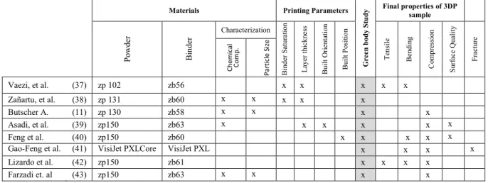
Several studies have been conducted to characterize the plaster-based printing materials as well as to optimize their parameters aiming to achieve best characteristics of the green 3DP models. The main characteristics analysed are: mechanical strength, surface quality and accuracy of green specimens. These studies are summarized in Table 3.
Table 3. Previous studies on the influence of different parameters in BJ green parts in plaster based materials
Materials Printing Parameters
Gre en b od y S tu
dy Final properties of 3DP sample
Po w de r B in de r Characterization B inder S atu ra tion L aye r thi ckne ss B uil t Or ienta tion B uil t P os itio n T ens ile B ending C ompr es sion Sur fa ce Qua li ty Fr ac tur e Ch e m ic al Co m p . Pa rt ic le S ize Vaezi, et al. (37) zp 102 zb56 x x x x x Zañartu, et al. (38) zp 131 zb60 x x x x x Butscher A. (11) zp 130 zb58 x x x x Asadi, et al. (39) zp150 zb63 x x x x x x Feng et al. (40) zp150 zb60 x x x x x
Gao-Feng et al. (41) VisiJet PXLCore VisiJet PXL x x x x
Lizardo et al. (42) zp150 zb61 x x x x
Farzadi et. al (43) zp150 zb63 x x x x
The significant effects of printing parameters such as layer thickness and binder saturation level on flexural and tensile strengths properties, integrity, and dimensional accuracy of the 3DP were studied by Vaezi, et al.(37). Mechanical tests and microscopic examinations were carried out to find that layer thickness and binder saturation level, combined together, have a significant effect on strength, integrity, and dimensional accuracy of green body part.
13
volume per layer, type of binder and temperature on mechanical properties of green body parts, made with an experimental 3DP equipment based on a spiral growth manufacturing (SGM) device. Two types of binder fluids (zb®60 and demineralized water) and one plaster-based material (zp®131) were used and characterized. They found that the layer thickness has the highest effect on apparent density, hardness and fracture strength on the green 3D printed parts. The binder saturation is significant on fracture strength when considered together with the layer thickness.
Relevant calcium phosphate-based powder properties such as powder particle size, flowability, wettability and compaction rate were analysed and discussed in order to optimize these properties and achieve successful results. These characterizations formed the basis for obtaining geometric and dimensional accuracy in structures for scaffold engineering built by 3D printing (11).
The major printing parameters examined by Asadi et al. (39), were layer thickness, delay time of spreading the next layer, and build orientation of the specimens, to optimize them in the manufacture of a prototype scaffold with calcium sulphate-based material, and commercial 3DP material (zp®150 and zb®63). They identified that layer thickness is the most influential parameter on the quality of scaffolds built by 3D printing. In addition, when coupled build orientation and new layer spreading delay time, they constitute the most important factors influencing the dimensional accuracy, compressive strength, and porosity of the samples.
Feng et al. (40), conducted tests with printed samples using commercial 3DP materials (zp®150 and zb®60). The surface structure of cubic 3DP samples, such as layered microstructure, striped structure and orthotropy was analysed. In addition, compression and bending tests were performed to determine the mechanical behaviour. They verified that the materials are orthotropic, and that both mechanical properties and failure depends on inter-layer and inter-strip (when the print nozzle applies the binder solution at predetermined locations, strip by strip until one layer is constructed), suggesting that the behaviour of 3D printed structures depends strongly on the printing direction.
The dynamic coalescence of cracks and the mechanical behaviour on bending and compression were studied in 3DP cubes with commercial plaster-based powder (Visijet PXLcore®). The behaviour of these 3DP models was compared with natural rocks. The crack paths and their development were captured by a high-speed camera revealing that the wing
14
crack may or may not occur at the tip of the present cracks. No characterizations were made to the 3D printing materials (41).
Pristine and infiltrated 3DP samples built with plaster-based material (ZPTM 150, and their ZbTM 61 binder) were tested in tensile, bending and compression. In this case, the 3DP models in green state were used as a reference to compare its mechanical behaviour when they were subsequently infiltrated. Likewise, no characterizations of the printing materials were made (42).
The effects of layer printing delay parameters on the physical (morphology) and mechanical properties (compressive strength, toughness and tangent modulus) of printed scaffolds were investigated. All mechanical properties of samples printed with a delay of 300 ms. were observed to be higher than other samples built with lower printing delays. This study carried out a brief chemical characterization and distribution of particle size analysis of the printing powder Zp 150® (43).
Most studies about binder jetting technology using plaster-based materials mainly analyse the printing parameters, and the final properties of some pristine structures (basically scaffolds), leaving a gap in characterization of printing materials.
The particle size and chemical composition of printing powder, along with other parameters, play an important role during 3D printing, also impacting the intermediate and final quality (morphology) of the product, while also having a direct influence on the infiltration process. Therefore, an appropriate knowledge of this material is required (44).
For particle size analysis, optical instruments based on the measurement of laser light scattered by the particles such as laser diffraction (LD) have now become a popular and standard laboratory technique. Compared with other particle sizing techniques, LD has the advantage of high speed, good reliability and high reproducibility. It is increasingly being applied for process and quality control of powder processes, both in solid–liquid suspensions and gas–solid systems (45, 46).
To analyse the chemical composition and morphological properties of powder materials an elemental analysis technique Energy Dispersive Spectroscopy (EDS) was used, where samples are stimulated by electrons or high-energy photons, and detect the spectrum of outgoing photons. It is usually combined with scanning electron microscopy, which makes it a versatile tool for acquiring a composition map of the sample (47). The EDS technique, when integrated with dedicated software package for element identification (EID), measures strength of association between particle spectra and reference library spectra (software). Correlation
15
strong correlation.
The present chapter proposes to characterize the printing powder by size distribution and chemical composition, and analyse the morphology and chemical composition of a green 3D printed model. These results will provide a clear view of the base material and the constitution of the green 3DP model. This could create an important opportunity to improve the infiltration process.
2.2 Materials and 3D Printer 2.2.1 3D Printing materials
All 3D printing components and test samples were built with plaster-based powder, commercially known as VisiJet PXL® Core (48), and water based binder solution VisiJet PXL® (3D Systems, USA) (39, 49). This material system offers numerous capabilities to build high-definition full colour concept models for a variety of commercial applications, assemblies and prototypes.
The main constituent of the printing powder (VisiJet PXL® Core) is 80 - 90% calcium sulphate hemihydrate (CaSO4.0.5H2O), with a melting point of 1450 ºC and density of 2.6 – 2.7 g.cm-3 and a water solubility of 0.83% (20 ºC in gl-1) (48).
The binder used throughout this work is VisiJet PXL® clear. The colourless version was always used, except where indicated otherwise. The VisiJet PXL® binder solution is not classified as a hazardous substance (50), and it has 98% water content, commercially formulated with a 2-pyrrolidone (0-1%). The pH of the binder at 20ºC is 9.8, and its boiling point is 100ºC, with a melting point of 0 ºC. It has a density of 1.0 gcm-3, and it is water soluble, with the viscosity similar to pure water (49).
2.2.2 3D Printer and parameters
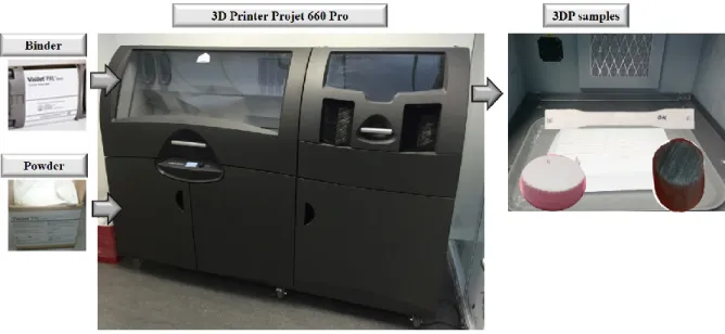
All 3DP specimens and models were designed in Solidworks® software and saved in “stl” files when no colour was required while wrml, ply or zrp files were used for colour models. These files were imported to the 3D printer Projet 660 Pro (3D Systems, USA) (51), available at the Laboratory of Development of Products and Services (LDPS) of the Faculty of Engineering of the University of Porto-FEUP (see Figure 6) . This 3D printer is equipped with a 3DPrint™ 1.0 System Software© and an automated power loading recycling and removal.
16
The 3D printer, with a build chamber of 254x381x203 mm has also a cabin for cleaning printed parts with a compressed air gun and drying system at 70ºC. The printer has a resolution of 600 x 540 dpi, layer thickness of 0.1 mm, and its 1520 inkjets allows a vertical build speed up to 28 mm/hour. These main characteristics of the 3D printer are showed in Figure 6.
Figure 6. 3D printer and printing materials with some printed specimens in the cleaning chamber
In order to avoid influence (noise) of the 3D printing process in the subsequent post-processing, when required (in the next chapters), the 3D printing process and respective parameters were adjusted and kept constant in this thesis (except where indicated otherwise). The printing process methodology is indicated in Figure 7 and the selected parameters are depicted in Table 4.
As it can be seen in Figure 7, once the design of the 3D model is generated, it is imported to the printer on a corresponding file format, where it can be edited. Printing details are adjusted and the model is positioned with the printer software.
The printer and material levels are checked, the printing parameters selected and the model printed. After printing, the parts are allowed to dry at 55ºC for 2 hours in the same 3D Printer’s build chamber.
The loose powder is then cleaned by the automatic vacuum system, removing the coarse loose powder, leaving only the fine loose powder to be manually sucked with nozzles of different diameter. The final cleaning is concluded by removing the remaining loose powder with compressed air gun and brushes of different sizes.
17
convection oven SLW53 STD (PolEko, Poland) at 60 °C for 24 hours, and oven cooling. The samples are then stored in airtight containers until their use.
Figure 7. 3D printing process methodology
The printing parameters were selected based on two criteria; first, the flexibility of varying parameters within the printer range, and second, discarding those parameters that produce the best and the worst mechanical strength, opting for the ones that reflect the average mechanical resistance. This usually occurs using the "quick place" command (3D Print ® V1.0 software), (52). The default printing parameters used are shown in Table 4.
Table 4. Default printing parameters selected
3D printing parameters Values or condition
Build position Right rear corner of the build 3DP chamber
Build orientation (degrees regarding the X axis of the machine) 0 Saturation level at 100% binder/volume ratios (shell and core) 0.24; 0.12
Bleeding correction factors (X; Y; Z) 0.091; 0.071; 0.076 Layer thickness (mm) 0.01
Vertical building speed (mm/h) 28
Post-impression drying of specimens in the printing chamber 2 hours at 55 ºC Re-dry in oven 24 hours at 60 ºC
To print a batch of 3D specimens, it was preferred to select the build orientation of 0 degrees regarding the X axis, while the build position was the right rear corner of the build 3DP chamber (except where otherwise specified) where the powder is best spread. Unlike other AM processes, these parameters do not turn out to be as influential. While it is true that the position for each sample has varied, this variation has been small, considering that the build position does not have a significant impact on the mechanical strength (53). In a general way, the strength of a non-infiltrated part will be somewhat affected by build orientation, but once a part is infiltrated, it uniformly takes the strength characteristics of the infiltrant product (52).
18
The binder saturation level is the ratio between the binder volume spread by the printing jets and the volume occupied by the 3D printed model. It is not recommended to activate the bleeding compensation function to build parts with features under 1.27mm, but using instead the default values of the machine (52).
2.3 Characterization of powder and green 3DP model
The methodology established in this chapter consists of: (i) characterization of the printing powder material by particle size distribution (PSD) and chemical composition analysis, and (ii) analysis of the morphology and chemical composition of the green 3D printed model. 2.3.1 Chemical composition and morphological analysis of powder and green 3DP model
The elemental chemical composition and morphological analysis, of both powder and green 3DP parts were carried out on a scanning electron microscope (SEM) (Phenom ProXL, USA), equipped with two detector systems, a fully integrated Energy X Ray Dispersive Spectroscopy (EDS), and Secondary Electron Detector (SED).
Detailed chemical powder composition, obtained from a micro volume via a spot analysis, was performed using an EDS analytical technique. Therefore, dry particles were charged and scattering them into the microscope chamber through a proprietary venting/loading mechanism. The elements were mapped with a beam acceleration voltage of 15 kV, and an acquisition real time of 265 seconds, supported by the dedicated software package Element Identification (EID). Due to the database included in the software, it was not necessary to change the use of external software packages or references to obtain a result of the elemental chemical composition.
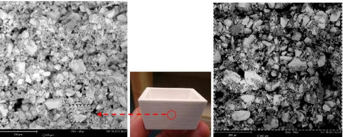
The morphological analysis and chemical composition of a green 3DP model was carried out on the larger side (outer surface) of the sample designed and printed as shown in Figure 8. This 3DP model was used in a previous study (see Appendix 1), whose internal CAD dimensions are: AxBxH = 35x25x20 mm, axb = 30x20 mm, and 4.0 mm thick wall (54).
19
a) b)
Figure 8. 3D model for microscopic analysis a) CAD design, and b) green 3DP model
This specimen was designed as a solid, and saved in stl format, later printed in the 3D printer Projet 660 Pro printer (3D Systems, USA), following the process and the parameters indicated above in 2.2.2.
2.3.2 Powder particle size distribution
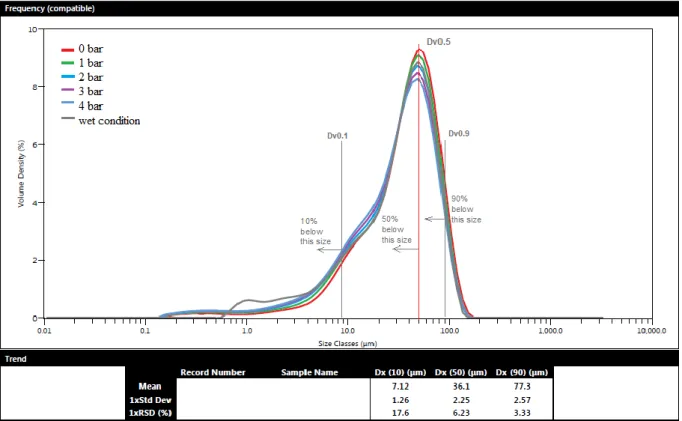
The particle size distribution of powder was performed in a Mastersizer 3000 equipment (Marlvern Instruments, UK) which uses the laser diffraction technology (LD), which is one of the most popular techniques to characterize particles due to its speed, easy use, and flexibility. It was performed in a wet and dry condition. For dry analysis, pressures of 0, 1, 2, 3 and 4 bar were used, while for the wet analysis, 2 bar of pressure and ethanol dispersant were used.
In laser diffraction measurements, the angular scattering intensity data was analysed to calculate the size of the particles that created the scattering pattern using the Lorenz-Mie theory (in ProSuite® software) of light scattering. Results of particle size distribution are therefore, reported as equivalent spherical diameters in volume distribution curves. The most common approach for expressing (LD) results is to report the D10, D50 and D90 values, based on a volume distribution. An additional approach to describe distribution width is normalizing the standard deviation by dividing it by its mean. This is approach is known as the Relative Standard Deviation or RSD (55). Table 5 summarizes the parameters used for both, wet and dry tests.
20
Table 5. Parameters for particle size analysis of powder by Laser Diffraction (wet and dry conditions)
Parameter specifications
Particle Name Gypsum (RI 1.525)
Dispersant Name Ethanol (for wet) Particle Absorption Index 0.100
Weighted Residual 0.35 %
Particle Refractive Index 1.525
Dispersant Refractive Index 1.360 (for wet)
Laser Obscuration 2.02% for dry and 6.09 % for wet
2.4 Results and Discussion 2.4.1 Powder Characterization
The results of the plaster-powder VisiJet PXL core® particle size distribution (PSD) are depicted in Figure 9, according to dry and wet dispersion conditions. These results are presented as equivalent spherical diameters in a volume distribution. The values corresponding to 10, 50 and 90% (D10, D50, and D90) of the PSD are highlighted in the same Figure 9.
This powder is characterized by a non-symmetric particle size distribution, with an equivalent diameter concentrated on 36.1 m. The greater relative standard deviation (RSD) was RSD-Dx10 = 17.2, while the smallest was RSD-Dx90 = 3.33. There is a high number of fine particles of up to 7.12 𝜇𝑚 in diameter, but their volume is only 10% (Dx10), while 50% reach diameters of up to 36.1 𝜇𝑚 (Dx50), and 90% reach a diameter of up to 77.3 𝜇𝑚. This characterization denotes that the powder is a material with a low degree of agglomeration.
The particle size distribution curve of VisiJet PXL core® powder, when contrasted with its predecessor, Zp 150® powder, maintain a similar trend. Its main difference is that the Zp150® powder consists of finer particles in all its representative statistical values. Thus, Zp 150® has Dx10 = 0.64 𝜇𝑚, Dx50 = 27 𝜇𝑚, and even its larger particles Dx90 = 69 𝜇𝑚 (43). The Zp131® powder shows an average particle size of approximately 40 𝜇𝑚 (38).
These results suggest that VisiJet PXL core® has an average grain size similar to Zp131®, but with respect to Zp 150®, it has improved tendency to packaging; however, the porosity generated in a 3DP model will be similar, so its behaviour in the infiltration post-processes will be identical in these two powders.
21 Figure 9. Overlay particle size distribution of 3D printing VisiJet PXL core® powder, in volume
density (%)
The dry dispersed particles were analysed by SEM, showing a noticeable differentiation both in size and appearance (colour contrast), as shown in Figure 10.