Acoustical characterization of the underground
chapels of the new Holy Trinity church in the
Fatima shrine, Portugal
António P. O. Carvalho
Lab. of Acoustics, Faculty of Engineering, University of Porto, Portugal, [email protected].
Bruno F. O. Nascimento
Lab. of Acoustics, Faculty of Engineering, University of Porto, Portugal, [email protected].
Summary
This paper presents the interior acoustic characterization of the Chapels of Reconciliation, underground chapels of the new Holy Trinity church in Fatima, Portugal. The results of in situ measurements are presented regarding Reverberation Time, RASTI (with and without the use of sound reinforcement system), sound levels and NC of the HVAC equipment and airborne sound insulation indexes between chapels. The results are compared with Portuguese Catholic churches of similar volume and the subjective opinion of users of these chapels is analyzed.
PACS no. 43.55.Fw
1. Introduction
The Chapels of Reconciliation are a part of the new Holy Trinity church (opened on October 12, 2007) to host the pilgrims of Fatima. This church, unique in Portugal (and rare in the world), in addition to its grandeur (the largest Portuguese church in number of seats) was the target of a significant acoustic design, which is still unusual in this type of work [1].
Acoustic measurements were already carried out in the main Holy Trinity church [2, 3]. The main goal of this work is now the acoustic characterization of the three Chapels of Reconciliation, according to objective acoustic parameters measured in situ. Through the analysis of the results takes place the characterization of the rooms and the comparison with the values of other Portuguese Catholic churches with similar volume. The subjective opinion of users of these chapels is also examined. 2. The Chapels of Reconciliation
2.1. Characterization 2.1.1. Introduction
The Chapels of Reconciliation are located in an underground area of the new Holy Trinity church: Chapel of the Blessed Sacrament (Chapel 1), Chapel of the Resurrection of Jesus (Chapel 2) and Chapel of the Death of Jesus (Chapel 3+4) (Fig. 1 and 2).
Figures 1 and 2 - The new Holy Trinity church (top) and its scale model with the location of the Chapels of Reconciliation (bottom) [4, 5].
2.1.2. Chapels of the Blessed Sacrament and of the Resurrection of Jesus
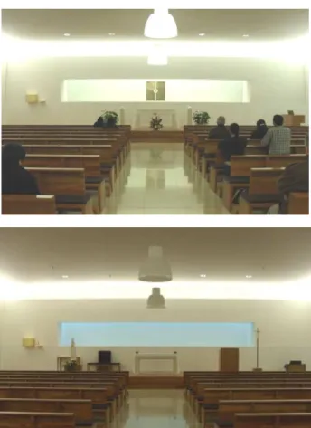
The Chapel of the Blessed Sacrament and the Chapel of the Resurrection of Jesus, here named Chapels 1 and 2 respectively (or C1, C2), are geometrically and visually similar (Fig. 3 to 5). The values of their main architectural features are: height = 4.8 m; width = 17.0 m; length = 19.0 m; area = 323 m2; volume = 1550 m3; number of seats = 216.
Figure 3 – Floor plan of Chapels 1 (right) and 2 (left) with lobby A in between.
The most relevant solutions adopted in the interior acoustic treatment in these two chapels (Fig. 4 and 5) are the rows of padded wooden pews (Fig. 6) which contribute essentially to the sound absorption at high frequencies and the wall panels applied with a vertical slope of about 5 degrees (Fig. 7) varying the thickness of the air space thus avoiding parallels walls to minimize the adverse effects of multiple reflections.
The floor is covered by marble and there is a 1.5 m height plywood dado around the entire length of the walls. The difference between these two chapels (C1, C2) is the coating in the upper part of the walls, as well as on the ceiling. In Chapel 1 this coating is made with Akustaplan panels [6], with high sound absorption coefficient values, while in Chapel 2 the panels are of gypsum board (very low sound absorption). This difference, which is reflected in the quite distinct acoustic behaviour between the two chapels, was proposed by the owner acoustical consultant (and approved by the Sanctuary) to potentiate speech intelligibility in Chapel 1 (lower RT) and to provide a more suited environment for music in Chapel 2 (higher RT). Both chapels are equipped with a sound reinforcement system (SRS) of two laterally positioned Bose loudspeakers (Crown amplification, BSS processing and AKG microphones) (Fig. 8).
Figures 4 and 5 – Chapel 1 (top) and Chapel 2 (bottom).
Figures 6 and 7 - Cushioned pews (top) and the slope of the wall panels to minimize multiple reflections (bottom).
A
C1 C2
Figure 8 - Loudspeaker Bose.
2.1.3. Chapel of the Death of Jesus
The architectural features of the Chapel of the Death of Jesus (Fig. 9 to 12) here named Chapel 3+4 or C3+4 (significantly different from C1 and C2) are: height = 4.8 m; width = 19.0 m; length = 35.0 m; area = 665 m2; volume = 3190 m3; number of seats = 588.
Figure 9 – Floor plan of Chapel 3+4 (with a moveable partition behind row 5).
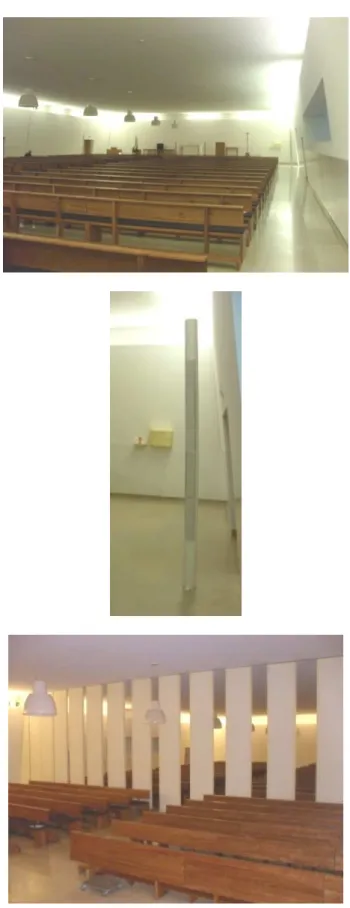
The interior materials in Chapel 3+4 are similar to those in Chapel 1. The padded pews act mainly at high frequencies and the walls are tilted from the vertical by about 5 degrees to prevent parallel walls, and to minimize the adverse effects of multiple reflections. The floor is also in marble with a 1.5 m height plywood dado. In the remainder part of the wall and ceiling the same Akustaplan [6] is used with high sound absorption coefficient values. The sound reinforcement system (SRS) is slightly different due to different dimensions of Chapel 3+4 when compared with Chapel 1, consisting of four BOSE loudspeakers (Crown amplification, BSS processing and AKG microphones), two on each side of the chapel and with different orientations (a speaker on each side oriented to cover an area closer to the altar and the other two targeted to cover an area furthest from the altar) (Fig. 11).
There is also a removable partition in Chapel 3+4 (Fig. 9 and 12) that enables the creation of two independent chapels, called Chapel 3 (the largest on the left in Fig. 9) and Chapel 4, to allow two separate ceremonies simultaneously.
Figures 10, 11 and 12 – Chapel 3+4 (top), Bose loudspeaker (middle) and removable partition between C3 and C4 (bottom).
C4 C3
2.2. Objectives for the acoustic parameters The main objective of the acoustics in a Catholic church is to achieve good speech intelligibility, regardless of the location of the listener, but still getting a musical environment as good as that intelligibility allows. The background noise should reveal a major design concern with achieving Silence because the church is a place for prayer and personal recollection.
The RASTI should have high values to allow good speech intelligibility throughout the space as the Word is a key vehicle in Eucharistic celebrations. For all that to happen, desirable values for these parameters are [1]:
LAeq ≤ 30 dB and NC ≤ 25 dB (background noise) RASTI ≥ 0.50
RT avg. (500, 1k Hz) ≈ 1 s for speech
RT avg. (500, 1k Hz) ≈ 2 to 4 s for music/hymns For the Reverberation Time (RT) two distinct ideal values were adopted for Chapels 1 and 2 to deliberately create two visually and geometrically identical spaces but with a very different acoustic behaviour (one more dead: C1 and another more dry: C2).
3. Measurements 3.1. Introduction
In situ tests were performed (March 2010) in the unoccupied chapels. Chapel 3+4, in addition of been tested in their mode of 588 seats, was also tested separately (that is, in Chapels 3 and 4 that arise from the use of a removable partition between them).
The parameters tested were:
• Reverberation time (RT) in 1/1 and 1/3 octave bands;
• RASTI (Rapid Speech Transmission Index), with and without the use of the existing sound reinforcement system [9];
• L (sound pressure levels by 1/3 octave bands) and related NC of background noise, with and without the operation of Heating, Ventilation and Air Conditioning (HVAC) equipment;
• D (level difference, for airborne sound insulation) between Chapels 1 and 2; between Chapel 2 and the lobby A and in Chapel 3+4 (between Chapels 3 and 4 separated) according to EN ISO 140-4 and 717-1.
The equipment used was B&K: 2260 sound level meter, 4224 noise source and 3361 RASTI.
3.2. Results and Discussion 3.2.1. Reverberation Time
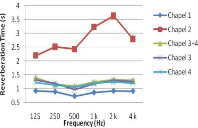
For the RT tests three measurement positions were chosen in each chapel and their mean value characterized the RT in each room. The results are visible in Fig. 13 and summarized in Table 1.
Figure 13 – Spectra of mean RT values for the five different chapels.
Table 1 - RT (500, 1k Hz) measured mean values for all the chapels and recommended ideal limits.
RT(500, 1k Hz) (s) Chapel
Average Ideal for speech Ideal for music
1 0.8 2 2.8 3+4 1.2 3 1.1 4 1.1 ≈ 1.0 ≈ 2 to 4 3.2.2. RASTI
The measured average RASTI results in six positions in each chapel are presented in Table 2 as well as their presumed speech intelligibility and ideal limits. Both Chapels 1 and 3+4 meet the ideal limits and have good speech intelligibility. Chapel 2 got only a mediocre conversion to the scale of subjective speech intelligibility.
Table 2 - Average RASTI values and related speech intelligibility, and ideal limits (SRS - Sound Reinforcement System). Situation RASTI avg. Speech intelligib. Ideal values Chapel 1 without SRS with SRS 0.68 0.69 Good Chapel 2 without SRS with SRS 0.42 0.42 Mediocre Chapel 3+4 without SRS with SRS 0.63 0.67 Good ≥ 0.50
3.2.3. Background noise
The sound levels (and related NC) from the background HVAC noise are presented in Table 3. The use of the HVAC equipment increased the LAeq between 1 and 14 dB depending on the chapel. Chapels 1 and 3+4 satisfy the ideal values for LAeq and NC but Chapel 2 does not.
Table 3 - Background noise LAeq with and without HVAC in operation, values of NC for each chapel, and ideal limits. LAeq (dB) Ideal values Chapel with HVAC without HVAC ∆LAeq (dB) NC (dB) LAeq (dB) NC (dB) 1 25 24 1 18 2 37 23 14 29 3+4 27 23 4 20 ≤ 30 ≤ 25
3.2.4. Airborne sound insulation
The airborne sound insulation between Chapels 2 and 1 (C2-C1), between Chapel 2 and the lobby (C2-A) and of the removable partition in Chapel 3+4 (C3-C4) are summarized in Figure 14 and Table 4. The insulation between Chapels 2 and 1 is noteworthy (59 dB) giving a large privacy if celebrations occur at the same time in these two chapels. This is due to the existence of an 8.6 m wide lobby separating them (fig. 3). As expected, sound insulation between Chapel 2 and the lobby (C2-A) is lower, given the existence of only one separating element, but with a very similar spectrum. The removable partition provides the lowest sound insulation, while not allowing a conversation to be clearly understood, does not permit concurrent celebrations in the Chapels 3 and 4 to be acoustically possible with quality.
Figure 14 - Values of the standardized level difference for airborne sound insulation (DnT) between Chapels 2 and 1 (C2-C1), between Chapel 2 and lobby (C2-A) and for the removable partition in Chapel 3+4 (C4-C3).
Table 4 – Weighted standardized level difference for field measurements of airborne sound insulation (DnT,w) between Chapels 2 and 1 (C2-C1), between Chapel 2 and lobby (C2-A) and for the removable partition in Chapel 3+4 (C4-C3).
Partition C2 – C1 C2 – lobby A C4 – C3
DnT,w (dB) 59 37 29
3.2.5. Comparison with churches with similar volume
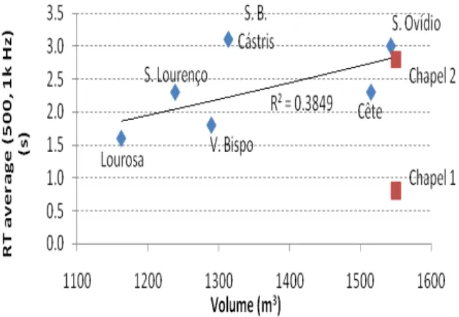
The RT and RASTI results obtained in Chapels 1 and 2 were compared with those in Portuguese churches with similar volume [7, 8] (Fig. 15 and 16). Chapel 1, that had an acoustic treatment so that their RT and RASTI values were ideal for speech intelligibility, achieves better results than the traditional Portuguese Catholic churches with similar volume. Chapel 2 had an acoustic treatment to become more reverberant, with values of RT and RASTI in line with those found in traditional Portuguese churches.
Figure 15 - Relationship among Volume and mean RT values (500, 1k Hz) of Chapels 1 and 2, compared with six Portuguese churches of similar Volume.
Figure 16 - Relationship among Volume and mean RASTI values in Chapels 1 and 2, compared with nine Portuguese churches of similar Volume.
When some users were asked in which of these two chapels (C1, C2) they prefer to listen the Services, they unanimously chose Chapel 2, which presents a more reverberant environment that is acoustically not favourable for word transmission. This reaction from the users by preferring the chapel that is objectively acoustically "worse" may be due to their habit to have assisted or performed countless celebrations in Portuguese traditional churches, which are usually far more reverberant and therefore more similar to the Chapel 2 rather than Chapel 1, more suitable for the transmission of the word. The subjective expectation on the part of users seems to exceed the objective acoustical quality of the site.
4. Conclusions
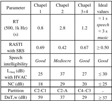
Table 5 presents a summary of the measurements results and ideal values.
For the RT, it is concluded that the differing acoustic treatment applied on the inner surfaces of the two chapels (C1, C2) had a strong influence on the measured values. Chapels 1 and 3+4, which were partly covered by highly sound absorbent Akustaplan panels, present mean RT values (0.8 and 1.2 s respectively) that are lower to the value measured in Chapel 2 (2.8 s), which does not have that absorptive material. Thus, Chapels 1 and 3+4 become acoustically more suitable for speech while Chapel 2 is best suited for music/hymns.
According to the RASTI evaluation, the chapels that had a better result in this parameter were again Chapels 1 and 3+4. Chapel 2 obtained a mean RASTI value considerably lower (-0.26) than the other chapels due mainly to its considerably higher RT value. It must be noticed that, a sound system as better as it is, if the chapel is not acoustically designed to enhance its performance in the speech intelligibility, cannot create excellent results. For the background noise, both LAeq and NC mean values for the three chapels are low. They increase by the functioning of the HVAC equipment but still providing a relaxing environment suitable for the purpose for which the chapels are intended which is the prayer and transmission of the Word.
The airborne sound insulation between Chapels 2 and 1, and between Chapel 2 and the lobby, are adequate for simultaneously services in these chapels with no acoustical interference. The sound insulation provided by the removable partition (C3-C4) does not allow the same to happen because, in spite of not letting a conversation to be clearly understood, the existing level of privacy is reduced.
Table 5 - Summary of average measured values and the ideals (C - Chapel, A - Lobby, SRS- sound reinforcement system). Parameter Chapel 1 Chapel 2 Chapel 3+4 Ideal values RT (500, 1k Hz) (s) 0.8 2.8 1.2 ≈ 1 s speech ≈ 3 s music RASTI with SRS 0.69 0.42 0.67 ≥ 0.50 Speech
intelligibility Good Mediocre Good Good LAeq (dB) with HVAC 25 37 27 ≤ 30 NC (dB) 18 29 20 ≤ 25 Partition C2-C1 C2-A C4–C3 - DnT,w (dB) 59 37 29 ≥ 37 Acknowledgments
This work was partially supported by the CEC - Centro de Estudos da Construção (FCT-FEUP) and by the Laboratory of Acoustics of the Institute of Construction (IC).
References
[1] A. Carvalho and D. Freitas: The new megachurch for the Sanctuary of Fátima, 10th ICSV Int. Cong. on Sound and Vibration, Stockholm 2003.
[2] P. Silva: Caracterização Acústica Interior da Nova Igreja da Santíssima Trindade em Fátima (in Portuguese), M.Sc. Civil Eng. thesis, Fac. Eng. U. Porto, Portugal, 2009.
[3] A. Carvalho and P. Silva: Sound, noise and speech at the 9000-seat Holy Trinity Church in Fatima, Portugal, Archives of Acoustics, 35(2) (2010) 145-156.
[4] www.pbase.com/diasdosreis/fatima_nova_igreja, acceded July 2010.
[5] www.santuario-fatima.pt, acceded July 2010. [6] www.dacoustie.com/images/stories/documents/ftakus
taplan.pdf, acceded July 2010.
[7] T. Silva: Guião da Acústica de Igrejas em Portugal (in Portuguese), M.Sc. Civil Eng. thesis, Fac. Eng. U. Porto, Portugal, 2008.
[8] C. Martins: Caracterização Acústica das duas Igrejas de Santo Ovídeo, Mafamude (in Portuguese), M.Sc. Civil Eng. thesis, Fac. Eng. U. Porto, Portugal, 2010. [9] CEI IEC 60268-16, Objective rating of speech