Metadata of the chapter that will be visualized in
SpringerLink
Book Title Technological Innovation for Cyber-Physical Systems Series Title
Chapter Title Offshore Wind Energy Conversion System Connected to the Electric Grid: Modeling and Simulation
Copyright Year 2016
Copyright HolderName IFIP International Federation for Information Processing
Author Family Name Seixas
Particle
Given Name Mafalda
Prefix Suffix
Division IDMEC/LAETA, Instituto Superior Técnico Organization Universidade de Lisboa
Address Lisbon, Portugal
Division
Organization Universidade de Évora
Address Évora, Portugal
Division
Organization Instituto Superior de Engenharia de Lisboa
Address Lisbon, Portugal
Corresponding Author Family Name Melício
Particle
Given Name Rui
Prefix Suffix
Division IDMEC/LAETA, Instituto Superior Técnico Organization Universidade de Lisboa
Address Lisbon, Portugal
Division
Organization Universidade de Évora
Address Évora, Portugal
Email [email protected]
Author Family Name Mendes
Particle
Given Name Victor M. F.
Prefix Suffix Division
Organization Universidade de Évora
Organization Instituto Superior de Engenharia de Lisboa
Address Lisbon, Portugal
Abstract This paper is on modeling and simulation for an offshore wind system equipped with a semi-submersible floating platform, a wind turbine, a permanent magnet synchronous generator, a multiple point clamped four level or five level full-power converter, a submarine cable and a second order filter. The drive train is modeled by three mass model considering the resistant stiffness torque, structure and tower in deep water due to the moving surface elevation. The system control uses PMW by space vector modulation associated with sliding mode and proportional integral controllers. The electric energy is injected into the electric grid either by an alternated current link or by a direct current link. The model is intend to be a useful tool for unveil the behavior and performance of the offshore wind system, especially for the multiple point clamped full-power converter, under normal operation or under malfunctions.
Keywords (separated by '-')
Modeling Simulation Offshore wind energy conversion Power converters Energy transmission -Harmonic distortion
to the Electric Grid: Modeling and Simulation
Mafalda Seixas1,2,3, Rui Melício1,2(✉), and Victor M.F. Mendes2,3 1 IDMEC/LAETA, Instituto Superior Técnico, Universidade de Lisboa, Lisbon, Portugal
[email protected] 2 Universidade de Évora, Évora, Portugal
3 Instituto Superior de Engenharia de Lisboa, Lisbon, Portugal
Abstract. This paper is on modeling and simulation for an offshore wind system equipped with a semi-submersible floating platform, a wind turbine, a permanent magnet synchronous generator, a multiple point clamped four level or five level full-power converter, a submarine cable and a second order filter. The drive train is modeled by three mass model considering the resistant stiffness torque, struc‐ ture and tower in deep water due to the moving surface elevation. The system control uses PMW by space vector modulation associated with sliding mode and proportional integral controllers. The electric energy is injected into the electric grid either by an alternated current link or by a direct current link. The model is intend to be a useful tool for unveil the behavior and performance of the offshore wind system, especially for the multiple point clamped full-power converter, under normal operation or under malfunctions.
Keywords: Modeling · Simulation · Offshore wind energy conversion · Power converters · Energy transmission · Harmonic distortion
1
Introduction
The focus of this paper is on the modeling and simulation of offshore wind energy conversion systems (OWECS) connected to the electric grid either by an alternated current link or by a direct current link in a view of timeliness developments on electricity sector restructuring and integrating the relevant dynamics [1]. Besides the electricity transmission, the system consists of a semi-submersible floating platform; a variable speed wind turbine; a mechanical transmission system described respectively by one, two, three, or five masses; a synchronous generator with excitation provided by means of permanent magnets; an electronic power converter, respectively described by a two level converter or by a multilevel converter in a multiple point clamped topology of three, four, five, or p levels [1–3].
The control of the system employs pulse width modulation (PWM) by space vector modulation (SVM) associated with sliding mode (SM) and proportional integral (PI) controllers. The behaviors resulting from the fact that wind energy is a variable, inter‐ mittently source of energy, as well as, due to eventual malfunctions of devices control‐ ling the systems are studied using computer simulations.
AQ1
© IFIP International Federation for Information Processing 2016
Published by Springer International Publishing Switzerland 2016. All Rights Reserved L. Camarinha-Matos et al. (Eds.): DoCEIS 2016, IFIP AICT 470, pp. 1–17, 2016. DOI: 10.1007/978-3-319-31165-4_37
The research question is about the model of the offshore wind system who is intend to be a useful tool for unveil the behavior and performance of the offshore wind system, especially for the multiple point clamped full-power converter, under normal operation or under malfunctions.
The novelty of the contribution of the research work are the modeling allowing a simulation of OWECS integrating the fundamental components and considering both AC or DC power transmission; the integration of the modeling of the multilevel converter in a multi point clamped diode configuration of three, four, five levels or p levels; the mitigation of the imbalance in the multilevel converter capacitor banks voltages [1–3].
2
Relationship to Cyber-Physical Systems
Nowadays there is a global integration increase of renewable energy systems in the existing electric grid, i.e., power system. The majority of renewable technologies are reliant on weather conditions and demanding regarding the integration into the electric grid. The answer to this demand, that needs to be fully resolved, entails advances in smart grid systems. This type of systems possibly will include micro-grids, energy storage facilities and might enable the coexistence of power systems with transportation and heating/cooling, representing in this manner complex energy systems [4].
Assuring sustainable development is a huge challenge for power systems [5]. Tradi‐ tionally, power systems were designed to supply electrical energy observing security conditions. Due to the opening of the electricity markets the need of an adequate response to severe faults is even more important [6].
Wind power systems manifest variations in the output power due to the variations of wind speed or the marine waves, thus introducing a new factor of uncertainty and risk on the electrical grid posing challenges in terms of power system security, power system stability, power quality and malfunctions [2].
Power systems are usually pointed out as a reference example of cyber-physical systems (CyPS) [6], intending for example for construction of smart grids, for attaining a blackout-free electricity generation and distribution system or for optimization of energy consumption [5].
CyPS can be described as smart systems that include software and hardware, namely components for sensing, monitoring, gathering, actuating, computing, communication and controlling physical infrastructures, completely integrated and directly interacting to sense the alterations in the state of the surrounding environment [7].
The integration OWECS into a electric grid, raises many concerns regarding oper‐ ation and reliability, not only because of the weather conditions, as well as the severity of the environment location and the eventual difficulty to access the physical installation. Thus, the use of smart devices such as CyPS, to assist monitoring, control and operating OWECS in a smart grid context [2] are fundamental pieces in the success of these systems.
However, integrating the CyPS engineering and technology in the already existing electric grid and other utility systems is a challenge. A major challenge for CyPS is the conception and the implementation of a power system infrastructure that is capable of providing blackout free electricity generation and distribution, that is flexible enough to allow mixed energy supply to or withdrawal from the grid, and that is resistant to acci‐ dental or intentional manipulations [7]. So, the successful integration of the cyber and the physical system components will obligate to an understanding of the multi-scale, multi-physics models and abstractions that will be required to allow the coexistence of software, communications, and interacting physical subsystems [7]. In this sense, the successfully integration of an OWECS into an electric grid, needs models more accurate and nearer to the reality. The model presented in this paper for an OWECS is intended to provide a useful toll in the analysis of a multi-disciplinary physical system in smart grid context.
3
Modeling
The modeling of the OWECS takes into account the mechanical, the electrical and the electronic fundamental components, integrating those inner systems in order to unveil the behavior and performance of the OWECS.
Figure 1 shows the layout of the OWES, considering AC energy transmission with a five level converter.
C3 C2 C1 ic3 1 2 3 PMSG ik 2 θ Lft Rft Ln Rn Cft iftk uftk uk 0 ik ic2 ic1 Wind C4 ic4 4 A A B B k=4,5,6 k=1,2,3 C C Eletric Grid Offshore Wind System Submarine Cable + Filter
Marine energy
ωb
Fig. 1. Layout of the OWES, AC transmission, five level converter.
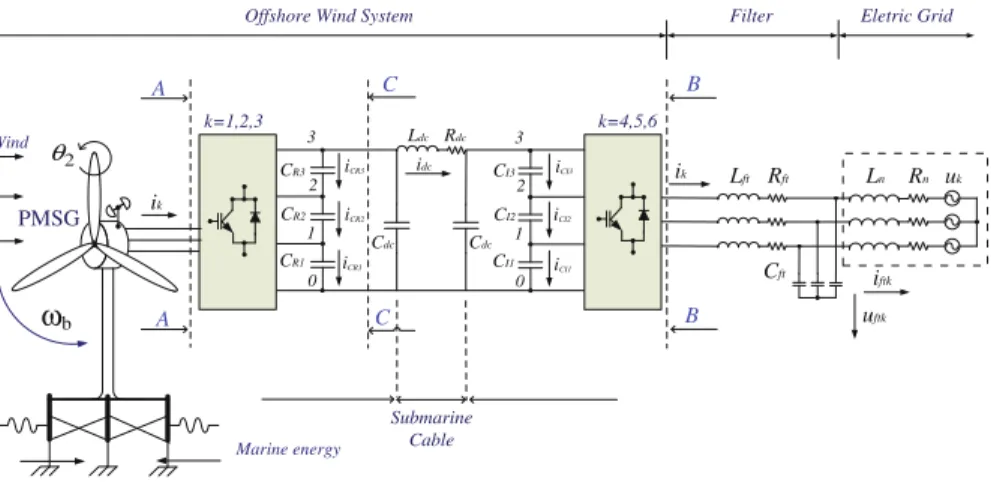
Figure 2 shows the layout of the OWES, considering DC energy transmission with a four level converter.
CR3 CR2 CR1 iCR3 1 2 3 ik 2 θ Lft Rft Ln Rn Cft iftk uftk uk 0 ik PMSG Wind CI3 CI2 CI1 1 2 3 0 idc Ldc Rdc Cdc Cdc A A B Submarine Cable k=4,5,6 k=1,2,3 B iCR1 iCR2 iCI3 iCI2 iCI1 C C Eletric Grid Offshore Wind System Filter
ωb
Marine energy
Fig. 2. Layout of the OWES, DC transmission, four level converter.
While the wind speed has a stochastic nature and generally varies considerably, for the purpose of the simulation in this paper the wind speed is modeled by a finite sum of harmonic terms, in the range 0.1 – 10 Hz and take three influences of the dynamic related with the action excited by wind on all physical structure as reported in [8]. The wind speed subject to disturbance is given by:
(1)
The mechanical power of the wind turbine has a model taking in consideration the three perturbations mentioned in (1). The mechanical power of the wind turbine is given by:
(2)
where
(3) The power coefficient cp is a function of the pitch angle and the tip speed ratio . Normally, numerical approximations are advised, as the one developed in [9] and followed in this paper. The mechanical power in (2) is computed by the mechanical power captured from the wind turbine without dynamic perturbations [8], in (3) asso‐ ciated with three perturbations, namely the asymmetry in the turbine, the vortex tower interaction and the eigenswings in the blades. The perturbations are computed by the formula given by:
(4)
where
(5)
The dynamic associated with the asymmetry in the turbine has the following data:
The dynamic associated with the vortex tower interaction has the following data:
The dynamic associated with the eigenswings in the blades has the following data:
The marine wave model [10] acting on the drive train is given by:
(6)
The elastic behavior of the tower and platform due to the surface motion action by marine waves in deep water, causes a resistant torque on the drive train [1] given by:
(7)
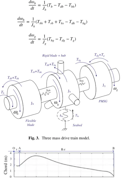
The wind turbines augmentation in size involves that the blades are more flexible and tend to bend. The blade bending occurs at a significant range of the joint between the blades and the hub. The modeling of the blades considers a splitting in two parts: a rigid one and a flexible one. Hence, the drive train is modeled by a discrete three mass model. The model for the drive train illustrated as shown in Fig. 3.
The first mass represents the concentration of the inertia of the flexible part of the blades; the second mass represents the concentration of the rigid part of the blades, hub, tower and platform, discarding the displacement between the different elements, but including the floating motion influence as a whole; the third mass represents the concen‐ tration of the inertia of the generator. The connection between the three masses is made through elastic couplings [11]. This three mass model has been proven as a good option [1] to study the system behavior in response to heavy disturbance. The model assumes a radius r of 2.5 m for the rigid part of the blades. The flexible part is in the range 2.5– 45 m. Figure 4 shows a comparison between both parts.
The state equations for modeling the mechanical drive train are based in the torsional version of the second law of Newton. The state equations for the rotational speeds of the three masses modeling shown in Fig. 3 are given by:
(8) (9) (10) Jb Jg Tb Trb+Tbh Tdb+Tbh Jh Flexible blade
Rigid blade + hub
PMSG Thg Tdh+Thg Tdg+Tg khs Ths Seabed kbh khg g ω b
ω
h ωFig. 3. Three mass drive train model.
Chord (m) Radius (m) 0 5 10 15 20 25 30 35 40 45 0 1 2 3 4 R-r B A O r
Fig. 4. Blade profile: rigid part OA, flexible part AB.
The equations that model the permanent magnet synchronous generator (PMSG) can be found in various texts [12]. In order to prevent demagnetization of the permanent magnet is imposed a null reference to the direct component of the stator current
[1].
An equivalent three-phase active symmetrical circuit given by a series of a resistance and an inductance models the electric grid. Thus, the electric current injected into the electric grid is given by:
(11)
In transient simulations this is the model that is normally used and corresponds to the model of an infinite grid linked by the equivalent series impedance.
3.1 AC Energy Transmission
The AC-DC-AC five level power converter is implemented by forty eight unidirectional commanded insulated gate bipolar transistors (IGBTs), identified by . Both the func‐ tionalities of rectifier and of inverter are implemented with twenty four [3], IGBTs each connected to a diode in an anti-parallel configuration. Following the PMSG the rectifier is linked before the voltage divider, which consists of four capacitor banks, with . Following the capacitor banks the inverter is linked before a second order filter, which is linked to an electric grid, see Fig. 1. A group of height IGBTs connected to the same phase composes the arm of the converter. For the five level power converter there is voltage levels. On each phase the voltage level is related
with the switching variable with . The switching variable iden‐
tifies the conduction or blockage state of the IGBT with of the converter arm defining the switching function on the IGBTs. The IGBTs state combinations for the converter arm, establish the level variable . The level variable is related with the charging state of the capacitor banks . The switching variable [1] is given by:
(12)
The level variable [1] is given by:
(13)
The output voltage of the rectifier [3] is given by:
(14)
The input voltage of the inverter is given by a similar function to (14), but with .
The capacitor bank current [5] as a function of is given by:
(15)
The sum voltage at the capacitor banks of the voltage divider is the voltage and is given by:
(16)
The submarine cable model is represented by an inductance and a resistance in series connected between the inverter and the second order filter. The model for the second-order filter is represented by an inductance , a resistance , and a capacitor bank with a capacity . The resistances and the inductances of the cable and filter are associated in equivalents resistance and inductance [1], respectively given by:
(17)
3.2 DC Energy Transmission
The AC-DC-AC four level power converter is implemented with thirty six unidirectional commanded IGBTs. Both rectifier and inverter functionalities are implemented with eighteen IGBTs, each connected to a diode in an anti-parallel configuration. Following the PMSG the rectifier is linked before a first voltage divider, which consists of three capacitor banks , located in the offshore semi-submersible platform. The inverter is connected between a second voltage divider formed by three capacitor banks and the second order filter connected before the electric grid, located in an electric substation on onshore. The submarine cable is connected between the first voltage divider down‐ stream of the rectifier and the second voltage divider upstream of the inverter, see Fig. 2. For the four level power converter there is voltage levels. On each phase the voltage level is related with the switching variable , given by:
(18)
The output voltage of the rectifier is given by:
(19)
The input voltage of the inverter is given by:
(20)
The current on each capacitor bank of the first voltage divider [2] is given by:
(21)
The current on each capacitor bank of the second voltage divider [2] is given by:
(22)
The voltage as a sum of the capacitor banks voltages of the first voltage divider is given by
(23)
The voltage as a sum of the capacitor banks voltages of the second voltage divider is given by:
(24)
A equivalent circuit models the submarine cable [2]. The submarine cable current state equation is given by:
(25)
4
Control Method
The OWECS employs PI controllers and the converters employ PWM by SVM associ‐ ated with SM. Power converters have variable structure behavior, because of the IGBTs switching states, conduction or blockage. Also, the variance in wind speed introduces model uncertainty. SM is known as a good choice for the control method for this type of structure. Switching frequency finite values 2 kHz, 5 kHz or 10 kHz are usually reported.
The physical limitation of finite switch frequency pf the IGBTs implies an expected error between the control value and the reference value. So, to guarantee that the system does not drifts away from the sliding surface is proved that has to hold a stability condition [14, 15] given by:
(26)
In order to establish a reference for the generator stator currents the error between the reference voltage and the capacitor voltage is used as the input of the rectifier controller. Meanwhile, the error between the reference stator current and the stator current is applied in the selection of the output space voltage vector in the (α, β) space, which in turn copes with the triggering of the rectifier IGBTs. The error between the reference voltage and the electric grid voltage is treated by the PI controller of the inverter intending to establish a reference for the inverter currents. The triggering of the inverter IGBTs is carried out using the error between the electric grid current and the inverter controller reference current.
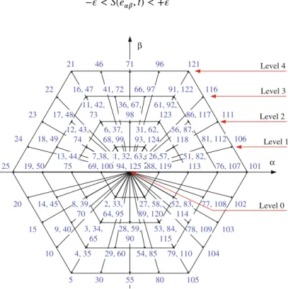
In practical implementations is allowed a limited error for , conse‐ quently is feasible to accept an error window, being this error window over time the sliding surface. So, the switching strategy is given by:
(27) α β 1, 32, 63, 94, 125 2, 33, 64, 95 6, 37, 68, 99 7,38, 69, 100 26,57, 88, 119 27, 58, 89, 120 31, 62, 93, 124 3, 34, 65 8, 39, 70 11, 42, 73 12, 43, 74 13, 44, 75 28, 59, 90 36, 67, 98 51, 82, 113 52, 83, 114 53, 84, 115 56, 87, 118 61, 92, 123 4, 35 9, 40 14, 45 16, 47 17, 48 18, 49 19, 50 29, 60 41, 72 66, 97 76, 107 77, 108 78, 109 81, 112 91, 122 54, 85 86, 117 5 10 15 20 22 23 24 25 30 46 55 71 96 121 101 102 103 104 105 106 111 116 79, 110 80 21 Level 0 Level 1 Level 2 Level 3 Level 4
Fig. 5. Output space voltage vectors, in (α,β) plane.
The integer voltage variables values and are in a domain set, limited by the converter voltage levels , i.e., comply with the relation given by:
(28)
The integer variables and permits to choose the most suitable vector from a set of 125 space vectors for the five level converter or from a set of 64 space vectors for the four level converter.
From the entire set of allowed space vectors there are redundant vector that identify different voltage levels. The control strategy processes a lessening on the unbalanced voltage of the capacitors banks through the consideration of vector tables [1], which consider the charging state of each capacitor bank and the voltage level. Figure 5 shows the output vectors for levels 0 to in the plane for the five level and four level converter.
5
Case Studies
The mathematical model for the OWECS with the five level converter with AC trans‐ mission or with the four level converter with DC transmission is executed in Matlab/ Simulink. The nominal power is 2 MW. The switching frequency for the IGBTs is 10 kHz. The mechanical mathematical model is represented by a three mass model. Figure 6 shows the average wind speed profile with perturbations.
0 1 2 3 4 5 0 5 10 15 20 25 30 Time (s) Wind speed (m/s)
Fig. 6. Wind speed profile. Figure 7 shows the marine height elevation.
0 1 2 3 4 5 −15 −10 −5 0 5 10 15 Time (s) S urface elevation (m)
Fig. 7. Marine height elevation.
5.1 AC Energy Transmission, Five Level Power Converter
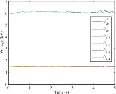
Figure 8 shows the DC voltage at the capacitor banks without unbalancing and the reference voltage. 0 1 2 3 4 5 0 1 2 3 4 5 6 7 Time (s) Volta g e (kV) U dc * U dc U C1 U C2 U C3 U C4
Fig. 8. Capacitors banks DC voltages without unbalancing. Figure 9 shows the instantaneous current injected into the electric grid.
3.4 3.42 3.44 −1000 −500 0 500 1000 Time (s) C u rrent (A)
Fig. 9. Current injected in the electric grid.
The Discrete Fourier Transform applied to process the total harmonic distortion (THD) is given by:
(29)
where is the harmonic root mean square value and is the fundamental compo‐ nent root mean square value.
Figure 10 shows the THD of the current injected into the electric grid.
0 1 2 3 4 5 0 0.2 0.4 0.6 0.8 1 Time (s) THD (%)
Fig. 10. THD of the current injected into the electric grid.
AQ2
5.2 DC Energy Transmission, Four Level Power Converter, Rectifier Voltage Malfunction
The rectifier malfunction at one phase on an IGBT occurs between 2.45 s and 2.80 s, imposing of the normal voltage value. Figure 11 shows the submarine cable DC current. Figure 12a and b shows the DC voltages on the capacitor banks and the reference voltage at the rectifier side and at the inverter side, respectively.
0 1 2 3 4 5 −2 −1.5 −1 −0.5 0 0.5 1 1.5 2 Time (s) DC c u rrent (kA)
Fig. 11. Submarine cable DC current.
0 1 2 3 4 5 0 2 4 6 8 10 Time (s) DC volta g e (kV) U dc * U dcR UCR1 UCR2 UCR3 (a) (b) 0 1 2 3 4 5 0 2 4 6 8 10 Time (s) DC volta g e (kV)
Udc* UdcI UCI1 UCI2 UCI3
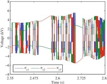
Fig. 12. Capacitor banks DC voltages; a) rectifier side; b) inverter side. Figure 13 shows the rectifier input voltage malfunction.
Figure 14 shows the DC current at the capacitor banks at the rectifier side and at the inverter side, respectively.
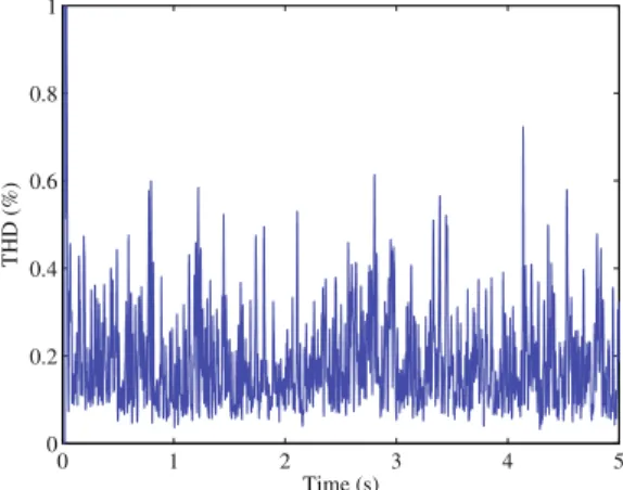
Figure 15 shows the THD of the current injected into the electric grid.
0 1 2 3 4 5 0 0.2 0.4 0.6 0.8 1 Time (s) THD (%)
Fig. 15. THD of the current injected into the electric grid.
2.35 2.475 2.6 2.725 2.85 −8 −6 −4 −2 0 2 4 6 8 Time (s) Volta g e (kV) u s1 us2 us3
Fig. 13. Rectifier input voltage malfunction.
0 1 2 3 4 5 −3.5 −2.5 −1.5 −0.5 0.5 1.5 2.5 3.5 Time (s) DC c u rrent (kA) iCR1 iCR2 iCR3 (a) 0 1 2 3 4 5 −3.5 −2.5 −1.5 −0.5 0.5 1.5 2.5 3.5 Time (s) DC c u rrent (kA)
iCI1 iCI2 iCI3
(b)
Fig. 14. Capacitor banks DC current; a) rectifier side; b) inverter side.
6
Conclusions
The increasing interest for the deployment of OWECS requires further research for modeling, allowing a value-added capability and suitable procedures not only at design phase, but also at operation, particularly on CyPS and smart grid context.
This paper presents a model for a simulation study for OWECS equipped with a PMSG with a multi point clamp multilevel power converter with AC or DC transmission. The case studies presented show that the model is a useful tool for unveil the behavior and performance of the OWECS, that the multi-level converter associated with the control strategy unveils the ability to lessen the unbalance of voltages at the capacitors bank, and that the use of multilevel converters is in favor in regarding the effect on the quality of the electric current injected in the electric grid.
OWECS are complex, very expensive and located far of shore where maintenance is very expensive. The suitable operation of such a system is a major issue. The inte‐ gration of OWECS on CyPS and smart grid context is important because real-time monitoring is allowed as well as the use of smart equipment with the capability to pre-detect malfunctions providing means to take the best decision on the capturing of power and acting measures on malfunctions through the use of model simulations as the one projected in this paper.
Acknowledgments. The work presented in this is funded through Portuguese Funds by the Foundation for Science and Technology-FCT for project scope LAETA 2015‐2020, UID/EMS/ 50022/2013.
References
1. Seixas, M.: Offshore wind energy conversion system connected to the electric grid: modeling and simulation. Ph.D. Thesis, Universidade de Évora (2015)
2. Seixas, M., Melício, R., Mendes, V.M.F.: Simulation of rectifier voltage malfunction on OWECS, four-level converter, HVDC light link: smart grid context tool. Energy Convers. Manage. 97, 140–153 (2015)
3. Seixas, M., Melício, R., Mendes, V.M.F., Couto, C.: Simulation of OWES with five-level converter linked to the grid: harmonic assessment. In: 9th International Conference on Compatibility and Power Electronics – CPE 2015, pp. 1–6, Lisbon, Portugal (2015) 4. Blaabjerg, F., Ionel, D.M.: Energy devices and systems – state-of-the art technology, research
and development, challenges and future trends. Electric Power Compon. Syst. 43(12), 1319– 1328 (2015)
5. Ramos, C., Vale, Z., Faria, L.: Cyber-physical intelligence in the context of power systems. In: Kim, T.-H., Adeli, H., Slezak, D., Sandnes, F.E., Song, X., Chung, K.-I., Arnett, K.P. (eds.) FGIT 2011. LNCS, vol. 7105, pp. 19–29. Springer, Heidelberg (2011)
6. Faria, L, Silva, A., Ramos, C., Gomez, L., Vale, Z.: Intelligent behavior in a cyber-ambient training system for control center operators. In: 16th International Conference on Intelligent System Application to Power Systems, pp. 1–6 (2011)
7. Foundations for innovation in cyber-physical systems - workshop summary report. National Institute of Standards and Technology (2013)
8. Akhmatov, V., Knudsen, H., Nielsen, A.H.: Advanced simulation of windmills in the electric power supply. Int. J. Electr. Power Energy Syst. 22, 421–434 (2000)
9. Slootweg, J.G., Polinder, H., Kling, W.L.: Representing wind turbine electrical generating systems in fundamental frequency simulations. IEEE Trans. Power Syst. 18, 516–524 (2003) 10. Eikeland, F.N.: Compensation of wave-induced motion for marine crane operations. Msc.
thesis, Norwegian University of Science, pp. 16–26 (2008)
11. Ramtharan, G., Jenkins, N.: Influence of rotor structural dynamics representations on the electrical transient performance of DFIG wind turbines. Wind Energy 10, 293–401 (2007) 12. Ong, C.-M.: Dynamic simulation of electric machinery: using Matlab/Simulink, pp. 259–350.
Prentice-Hall, New Jersey (1998)
13. Melicio, R., Mendes, V.M.F.: Simulation of power converters for wind energy systems. Información Tecnológica 18(4), 25–34 (2007)
AQ3
14. Barros, J.-D., Silva, J.F.: Optimal predictive control of three-phase NPC multilevel converter for power quality applications. IEEE Trans. Industr. Electron. 55, 3670–3681 (2008) 15. Melicio, R., Mendes, V.M.F., Catalão, J.P.S.: Document Modeling and simulation of wind
energy systems with matrix and multilevel power converters. IEEE Lat. Am. Trans. 7, 78– 84 (2009)
Author Query Form
Book ID : 419233_1_En
Chapter No.: 37
Please ensure you fill out your response to the queries raised below
and return this form along with your corrections
Dear Author
During the process of typesetting your chapter, the following queries have arisen. Please check your typeset proof carefully against the queries listed below and mark the necessary changes either directly on the proof/online grid or in the 'Author's response' area provided below
Query Refs. Details Required Author's Response
AQ1 Please confirm if the corresponding author is correctly identified.
Amend if necessary.
AQ2 Equations have been renumbered, as Eq. (28) has been repeated.
Please check and confirm.
AQ3 Reference [13] is given in the list but not cited in the text. Please
cite this in text or delete from the list.
MARKED PROOF
Please correct and return this set
Instruction to printer
Leave unchanged
under matter to remain
through single character, rule or underline
New matter followed by or or or or or or or or or and/or and/or e.g. e.g. under character over character new character new characters through all characters to be deleted
through letter or
through characters under matter to be changed under matter to be changed under matter to be changed under matter to be changed under matter to be changed Encircle matter to be changed (As above) (As above) (As above) (As above) (As above) (As above) (As above) (As above) linking characters through character or where required between characters or words affected through character or where required or