Next Generation Application Processor
Based on the IEEE 1451.1 Standard and Web Services
Vítor Viegas
1,2, J.M. Dias Pereira
1,2, P. Silva Girão
21ESTSetúbal-LabIM, Instituto Politécnico de Setúbal, 2910-761, Setúbal, Portugal 2Instituto de Telecomunicações, Av. Rovisco Pais, 1, 1049-001, Lisboa, Portugal
Phone: +351-265790000, Fax: +351-265721869, Email: [email protected]
Abstract – Over the last decade, the 1451.1 Std has
been a reference model to develop smart and open distributed measurement and control systems. Now, that the 1451.1 Std is about to be revised, there is the opportunity to enrich it with emergent and successful technologies as is the case of Web Services. Following this idea, we present a prototype of Network Capable Application Processor (NCAP) that runs on the .NET Framework and exposes its functionality through a set of Web Services. The prototype takes advantage of three key technologies: (i) the abstraction layer proposed by the 1451.1 Std; (ii) the interoperability provided by Web Services; and (iii) the productivity supplied by the .NET Framework.
Keywords – Smart Transducer, IEEE 1451.1, NCAP, Web Services, .NET Framework, client/server, publish/subscribe.
1. INTRODUCTION
This paper is divided in three main parts: we start by introducing the key technologies that were used to develop our work; secondly, we describe the implementation of the NCAP prototype stressing its transducer and network interfaces; and finally, we present an application example to extract results and draw conclusions.
1.1. IEEE 1451.1 Std
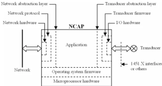
The IEEE 1451 family of standards defines a set of hardware and software interfaces that act as plugs where heterogeneous components can be connected and work together. The 1451.1 Std [1], in particular, defines a generic object model suitable to represent any networked transducer. This model must be implemented in a processor, known as NCAP, which acts as a bridge between transducers and the communication network (figure 1). On the field side, an abstraction layer provides high-level functions to communicate with transducers. The 1451.1 Std strongly recommends the adoption of 1451.X transducer interfaces [2-5] but other alternatives still remain open. On the network side, an abstraction layer provides high-level services to handle network requests. In the middle, the NCAP application processes data received from both sides (the field and the network) and decides the next state of the system.
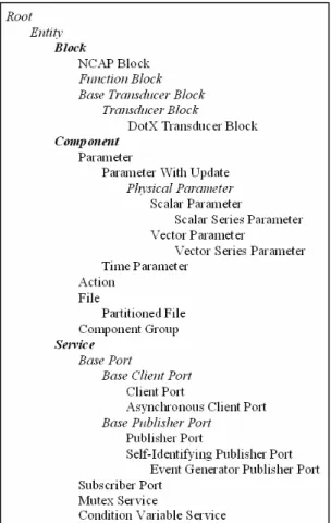
The object model proposed by the 1451.1 Std is composed by a hierarchy of classes divided in three main categories (figure 2):
• Block classes intended to do data processing. • Component classes intended to encapsulate data. • Service classes intended to handle inter-NCAP
communication and perform system-wide synchronization.
The objects created from these classes are the bricks used to build the NCAP application. The hierarchy is extensible by adding non-1451.1 classes to satisfy particular requirements of a given application. NCAP manufacturers shall develop the object model for their product and deploy it as a reusable software library.
The 1451.1 Std provides two models for inter-NCAP communications: a tightly-coupled client/server model for one-to-one communications; and a loosely-coupled publish/subscribe model for one-to-many communications. Using the client/server model, a client NCAP can invoke a function on the server NCAP and consume any results returned. Three invocation modes are available:
• Synchronous mode: The client blocks itself waiting for the server to respond.
• Asynchronous mode: The client makes the remote call and continues its execution path. Later, it can query the network infrastructure to see if the server has finished the call, and if so, request any data returned.
• Send-and-forget mode: This mode is similar to the previous one. The only difference is that the client does not care about any returned data at all.
Using the publish/subscribe model, the publisher NCAP can broadcast messages on the network whenever it has some kind of public announcement to make. These messages, known as publications, contain metadata describing the syntax and semantics of the information they carry. Based on this metadata, any subscriber NCAP can filter the publications of its interest and consume their attached data. This model is a very efficient way to implement distributed events.
1.2. Web Services
In simple terms, Web Services [6-7] are object methods exposed via eXtended Markup Language (XML) messages. These messages use a format protocol known as Simple Object Access Protocol (SOAP) [8] and travel across the network using a transport protocol like the Hyper Text Transport Protocol (HTTP). Every Web Service is described by an XML document, known as its manifest, which is written according the Web Service Definition Language (WSDL) [9]. This manifest describes the interface of the service, including the signatures of available methods, the data types used for all input and output parameters, and a list of supported communication paths. This information is all the client needs to consume the service without worrying about
its underlying implementation. Interoperability is achieved by imposing strong standards (SOAP and WSDL) and by using ubiquitous technologies (XML and HTTP). Being supported by the World Wide Web Consortium (W3C) [10], which includes all the major software companies around the world (such as IBM, Microsoft and Sun Microsystems), Web Services have the chance to become the first wide-used middleware solution and the answer for many interoperability problems.
1.3. .NET Framework
The .NET Framework [11-12] is a pre-fabricated software infrastructure released by Microsoft to develop and execute Windows applications. The .NET Framework includes three main components:
• A high-performance virtual machine that executes managed code in a secure and protected environment (conceptually similar to the Java virtual machine).
• An extensive class library that provides ready to use components to develop desktop and Internet applications.
• A set of last-generation programming languages, such as Visual Basic .NET and C#, designed to increase productivity.
By the end of 2006, version 3.0 of the .NET Framework was released including a new software package called Windows Communication Foundation (WCF) [13]. The WCF contains pre-built classes designed to develop secure, reliable, and interoperable distributed applications. The WCF supports the last enhancements in terms of Web Services providing many useful facilities such as hosting, service instance management, asynchronous calls, reliability and security. The WCF provides developers with the essential off-the-shelf plumbing required by any service-based application, and as such, it greatly increases productivity.
2. NCAP PROTOTYPE
The description of the NCAP prototype is divided in three sub-sections: we start by presenting its service-oriented object model; secondly, we talk about its transducer interface; and finally, we cover its network interface.
2.1. Object Model
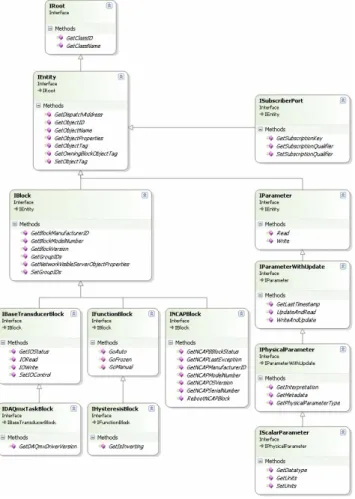
The NCAP prototype implements a fully-functional subset of the 1451.1 object model. As shown in figure 3, this subset is composed by thirteen classes, each one exposing a collection of methods according the recommendations of the 1451.1 Std.
Figure 2. IEEE 1451.1 Std class hierarchy. Classes listed in italic are abstract and shall not be instantiated.
The subset was developed using Visual Basic .NET and Microsoft Development Environment 2005 v8.0. It was compiled as a Dynamic Link Library (DLL), under the name IEEE1451Dot1.dll, and it can be reused by any Windows application.
The subset includes the following non-abstract classes:
• NCAPBlock: This class represents the NCAP Block which is the owner of all objects inside the NCAP process. Owning relations were implemented using a tree of pointers linking bottom-level objects to the top-level NCAP Block. The NCAPBlock class includes a boolean ParameterWithUpdate, named status, which reflects the execution state of the NCAP process: status = FALSE means that the NCAP Block is running normally; status = TRUE means that a software exception has occurred, and as such, the NCAP Block has become defective. • HysteresisBlock: This is a non-1451.1 class that
implements a simple ON/OFF controller, commonly known as schmitt-trigger, which consists of a comparator with hysteresis. During instantiation, the developer can choose if the hysteresis window is inverting or non-inverting. The HysteresisBlock class includes three objects: two floating-point ParametersWithUpdate, named highThreshold and lowThreshold, which define the high/low threshold values of the hysteresis window,
respectively; and a boolean ParameterWithUpdate, named output, which holds the decision of the comparator.
• DAQmxTaskBlock: This is a non-1451-1 class that implements the transducer interface of the NCAP prototype. More details will be given in section 2.2. • Parameter: This class provides services to
read/write a generic network-visible variable.
• ParameterWithUpdate: This class provides additional services to synchronize the network-visible variable with its owning Block. Whenever the variable is updated, a publication of type PARAMETRIC_DATA is fired to the network. • ScalarParameter: This class extends its parent by
including metadata structures that describe the content of the network-visible variable.
• SubscriberPort: This class takes an important role on the network interface of the NCAP prototype. More details will be given in section 2.3.
During the instantiation process, objects are initialized with startup data stored in a configuration file. By editing the configuration file, it is possible to tune the NCAP application without the need to recompile it.
2.2. Transducer Interface
Our prototype does not implement any of the standard 1451.X transducer interfaces. Instead, it communicates with Data AcQuisition (DAQ) boards compliant with the DAQmx technology [14] from National Instruments (NI). For that purpose, we built the DAQmxTaskBlock that wraps the NI supplied class library DAQmx.dll, which contains the .NET drivers that indeed communicate with the board.
The DAQmxTaskBlock takes advantage of pre-configured DAQmx tasks. A task is a set of properties that completely defines the process of acquiring/updating data. Examples of such properties are the hardware channel, input/output range, units, number of samples, sampling frequency and trigger settings. Using the Measurement and Automation Explorer (MAX), a software tool provided by NI, the developer can edit and save a given task. The task is then loaded by the DAQmxTaskBlock which executes read/write operations to transfer data from/to the field. Using MAX facilities, the developer can also add a custom scale to the DAQmx task. The scale act as a correction engine [2] by transforming raw field data into engineering units, and vice-versa.
At the moment, the DAQmxTaskBlock only supports scalar DAQmx tasks involving analog or digital variables. The scalar value is buffered on a ScalarParameter, named publicXdcr, which is included in the DAQmxTaskBlock class.
Our future plans for the transducer interface are to make it compliant with the 1451.4 Std and to extend it in order to support non-scalar quantities.
2.3. Network Interface
The network interface of our prototype is completely based on Web Services. Although Web Services are natively prepared to implement the client/server communication model, our prototype implements the publish/subscribe model as well. All object classes presented in figure 3 were implemented as WCF Web Services following the best practices described in the literature [15]. Whenever a WCF service is created, it registers on the network using a reliable HTTP endpoint and exposes a set of methods according the recommendations of the 1451.1 Std. If a client wants to invoke a method, it accesses the Web Service, creates a proxy at run-time and executes the remote call using one of the invocation modes (synchronous, asynchronous or send-and-forget). This way, there is no need to implement 1451.1-ClientPorts because WCF automatically handles the client/server communication model.
To implement the publish/subscribe communication model we built a WCF version of the 1451.1-SubscriberPort, which is in charge for listening to incoming publications. The listening process takes place in a multicast endpoint using the User Datagram Protocol (UDP). If a publisher wants to issue a publication, it accesses the multicast endpoint, creates a proxy at run-time and executes the remote call Publish using the send-and-forget invocation mode. The proxy interprets the role of 1451.1-PublisherPorts because the publication reaches all listeners registered in the multicast endpoint.
3. NCAP APPLICATION
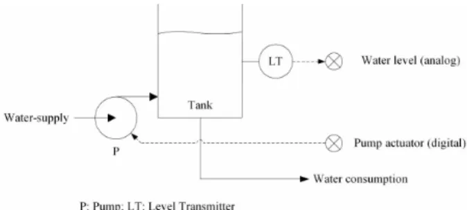
To demonstrate the effectiveness of our prototype we built a NCAP application that implements a simple ON/OFF controller with hysteresis. The controller can be applied to the water-supply system presented in figure 4. By turning the pump ON and OFF, the system works to maintain the water level between two threshold values (say 20% and 80% of the tank capacity). Assuming that the filling rate, when the pump is ON, is higher that the consumption rate, water never misses for consumption and it never exceeds tank walls.
As shown in figure 5, the NCAP application runs in Windows XP environments with .NET Framework v3.0 installed. It was developed using Visual Basic .NET and Microsoft Development Environment 2005 v8.0.
The NCAP application is composed by the following objects:
• pcNCAP: This object is an instance of the NCAPBlock class. It represents the NCAP process as a whole and keeps track of all underlying network-visible entities.
• pcNCAP.status: This object is an instance of the ParameterWithUpdate class. It signals eventual
exceptions occurred during the execution of the NCAP application.
• levelController: This object is an instance of the HysteresisBlock. It implements the control algorithm that decides the next state of the pump. • levelController.high/lowThreshold: These objects
are instances of the ParameterWithUpdate class. They hold two floating-point network-visible variables representing the high/low thresholds of the control algorithm.
• levelController.output: This object is an instance of the ParameterWithUpdate class. It holds a boolean network-visible variable representing the output of the control algorithm.
• levelInput: This object is an instance of the DAQmxTaskBlock. It acquires the signal provided by a level transmitter connected to an analog input of the DAQmx board. For the present case, we used the board NI USB-6008. The signal is converted to relative units (% of tank capacity) by the built-in correction engine.
• levelInput.publicXdcr: This object is an instance of the ScalarParameter class. It holds a floating-point network-visible variable representing the water level.
• pumpOutput: This object is an instance of the DAQmxTaskBlock. It updates the actuator of the pump connected to a digital output of the DAQmx board.
• pumpOutput.publicXdcr: This object is an instance of the ScalarParameter class. It holds a boolean network-visible variable representing the state of the pump.
• subscriber: This object is an instance of the SubscriberPort class. It listens to all incoming publications on the multicast endpoint with address soap.udp://239.255.1.1:8000/blackBoard.
The NCAP application presents a tree of all instantiated objects including their class IDs, class names and dispatch addresses. A column showing the instantaneous values of Parameters is also provided. The control algorithm is executed periodically by means of a timer that ticks ten times per second. All client/server communications take place on port 8000.
4. RESULTS
To interact with the NCAP application, we built a tiny client using the same development tools referred previously plus NI Measurement Studio v8.1.
As shown in figure 6, the front panel of the tiny client provides two numeric controls to define the high/low thresholds of the control algorithm. It also provides a numeric box and a virtual LED to indicate the instantaneous values of the water level and pump state, respectively. In addition, a trend graph presents that same information as a function of time.
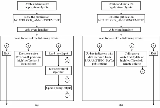
Figure 7 summarizes the internal functioning of the NCAP application and the tiny client. Both applications start by creating the top-level NCAP Block and its owning objects. All services are properly registered on the corresponding endpoints and Parameters are initialized to their default values. Once completed the startup process, both applications issue the publication NCAP_ ANNOUNCEMENT to inform the network about their presence. Afterwards, event handlers are enabled in order to start the processing phase, which is driven by the following occurrences (represented by numbered circles):
• Event 1: This event signals the execution of the control loop on the NCAP application. It is generated every 100 millisecond by a high-priority software timer. In every timer tick, the water level is read, the control algorithm is computed and the pump is actuated. During this process, the objects levelInput.publicXdcr, levelController.output and pumpOutput.publicXdcr are updated and the corresponding PARAMETRIC_DATA publications are drawn on the network.
• Event 2: This event occurs on the tiny client whenever it receives a PARAMETRIC_DATA publication containing information about the water level or the pump state. These publications are filtered by a SubscriberPort and the attached data is used to update the indicators on the front panel. This is a classic application scenario for the publish/subscribe communication model.
• Event 3: This event occurs on the tiny client whenever the user changes threshold values using the numeric controls. Consequently, the tiny client calls the service WriteAndUpdate on the corresponding ParameterWithUpdate hosted by the NCAP application. The remote call is made using the synchronous mode of the client/server communication model.
Figure 5. Screenshot of the NCAP application.
Figure 6. Screenshot of the tiny client. This test was carried under the following conditions: tank capacity = 10 litre; input flow = 9 litre/minute; and output flow = 3 litre/minute.
• Event 4: This event occurs on the NCAP application whenever the objects levelController.high/lowThreshold receive a remote call to the service WriteAndUpdate.
• Event 5: This event is generated when the user closes the application.
For this simple example, we used configuration files to statically bind service endpoints on both sides (the NCAP application and the tiny client). In the future, dynamic binding shall be implemented by taking advantage of NCAPBLOCK_ANNOUNCEMENT publications.
The mention to commercially available products from specific vendors was done only to exemplify application scenarios of the proposed NCAP solution. Obviously, interoperable products from others manufacturers may also be considered.
5. CONCLUSION
This paper demonstrates that it is possible to combine the 1451.1 Std with Web Services in order to build a service-based application processor. The proposed NCAP prototype implements the client/server communication model using native WCF facilities. It also implements the publish/subscribe communication model using a dedicated WCF Web Service connected to a multicast UDP-based endpoint. In addition, the prototype implements a correction engine and extends transducer interfaces by supporting DAQmx boards. Finally, our prototype takes advantage of the productivity supplied by the .NET Framework and it is
completely interoperable with any Web Service compliant device.
REFERENCES
[1] IEEE Std. 1451.1-1999, “IEEE Standard for a Smart Transducer Interface for Sensors and Actuators – Network Capable Application Processor (NCAP) Information Model”
[2] IEEE Std. 1451.2, “IEEE Standard for a Smart Transducer Interface for Sensors and Actuators – Transducer to Microprocessor Communication Protocols and Transducer Electronic Datasheet (TEDS) Formats”, USA, 1998
[3] IEEE Std. 1451.3, “IEEE Standard for a Smart Transducer Interface for Sensors and Actuators – Digital Communication and Transducer Electronic Datasheet (TEDS) Formats for Distributed Multidrop Systems”, USA, 2004
[4] IEEE Std. 1451.4, “IEEE Standard for a Smart Transducer Interface for Sensors and Actuators – Mixed-Mode Communication Protocols and Transducer Electronic Datasheet (TEDS) Formats”, USA, 2004
[5] IEEE Std. 1451.5, “IEEE Standard for a Smart Transducer Interface for Sensors and Actuators – Wireless Communication Protocols and Transducer Electronic Datasheet (TEDS) Formats”, USA, 2007
[6] Adam Freeman, Allen Jones, “Microsoft .NET, XML Web Services Step by Step”, Microsoft Press, USA, 2003, ISBN 0-7356-1720-1
[7] www.w3.org/2002/ws
[8] http://www.w3.org/2000/xp/Group
[9] http://www.w3.org/2002/ws/desc
[10] www.w3.org
[11] David S. Platt, “Introducing Microsoft .NET”, 3rd Edition, Microsoft Press, USA, 2003, ISBN 0-7356-1918-2
[12] http://msdn2.microsoft.com/en-us/netframework/default.aspx
[13] http://msdn2.microsoft.com/en-us/netframework/aa663324.aspx
[14] http://zone.ni.com/devzone/cda/tut/p/id/5434
[15] Juval Lowy, “Programming WCF Services”, O’Reilly, USA, 2007, ISBN 0-596-52699-7