DEVELOPMENT OF
NON-CONVENTIONAL
CASTING PROCESSES
RUI JORGE DE LEMOS NETO
TESE DE DOUTORAMENTO
DOUTORAMENTO EM ENGENHARIA MECÂNICA
FACULDADE DE ENGENHARIA DA UNIVERSIDADE DO PORTO
D
2014ii | P a g e © Rui Neto, 2014
iii | P a g e
Acknowledgments
There were many people and entities who scientifically, financially and emotionally contributed to the realization of this thesis. It is therefore with great pleasure that I express my sincere gratitude to them.
To my late father, wood patternmaker for 49 years, who taught me the foundry fundaments and life values, namely that work is the basis of the life.
To Professor Ana Reis, Assistant Professor at the Faculty of Engineering of Porto who is a big friend and was the main driving force and the first responsible for the presentation of this thesis
To Professors Jorge Lino, Associate Professor at the Faculty of Engineering of Porto University, and Professor Teresa Duarte, Assistant Professor at the Faculty of Engineering, for the motivation and tireless support. I also thank the confidence that always placed in my work, but above all, I thank the friendship always demonstrated. To Professor Antonio Torres Marques, Full Professor at the Faculty of Engineering of Porto, the numerous attempts, often frustrated, immovable and constantly renewed to take this work forward.
To Professor António Barbedo de Magalhães, Professor Emeritus already retired, my true master and great friend, the tireless attempts to get me to take this work forward and the unshakable confidence that for 34 years always placed in me.
To all my students, especially the ones who intervened in these teamwork the kindness with which they heard me, and especially what they taught me.
To my family, the incentives they gave me, the patience when they were deprived of my company and especially how joyfully they faced the formalization of this work, probably more than me.
To INEGI, INEGI managers and whole team, particularly foundry team, I express my gratitude for the availability, knowledge and sharing determinant ideas for the implementation of this work. I also thank the kindness and warm words of support always given to me.
iv | P a g e To the Zollern and Comandita company, his General Manager Virgilio Oliveira and large whole team involved in the R&D projects, for putting the challenges, believing in INEGI and funding the projects.
To the entities that financially funded the R&D Projects that supported this research work: SAESCT-PII&DT/1/2011 Structural Program co-financed by CCDRN and QREN; TOOLING EDGE Mobilizer Project co-financed by ADI and QREN; HYPERTURB, COMPINTEGRA and COMTICAST Co-Promotion Projects co-financed by ADI and QREN; AEROVAC and MEDCAST Individual Zollern Projects co-financed by IAPMEI and QREN.
v | P a g e
Abstract
Despite the big interest of reactive titanium alloys and titanium aluminides, due to the enormous benefits brought to the automotive, aircraft and aerospace industry by the introduction and components in these alloys for medium to high temperature applications, the processing of these alloys is still of high complexity and difficulty. In this work, innovative processes have been developed for melting and pouring of these alloys. These developments also tackled the problem of the reactivity with refractory shells used in the investment casting of titanium alloys and titanium aluminides, as well as the rheological behavior of refractories used in the manufacture of shells for nickel alloys.
In this context, new solutions for melting and pouring titanium alloys using initially ceramic crucibles and at the end the cold skull induction melting were developed.
The first solution promoted high overheating and high filling capacity of the molds but did not guarantee the melting with acceptable contamination of conventional titanium alloys. The second solution aimed to decrease the oxygen content of titanium alloys caused by metal-refractory reactions during melting in ceramic crucibles. Nevertheless, the cold crucible solution imposed restrictions to overheating that decreased filling capacity. The global solution consisted on the development of a system using cold crucible and counter gravity with differential pressure pouring to overcome thickness limitations.
Furthermore, ceramic crucibles for casting applications of titanium aluminides and other reactive alloys have been investigated, namely its chemical formulations and manufacturing techniques. Moreover, these alloys (i.e., titanium alloys and titanium aluminides) are highly reactive in the liquid state, which lead to the formation of a hard and cracked layer rich in interstitial elements such as oxygen on the surface of the castings products, as a result of the chemical reduction of ceramic shells’s "facecoat" by liquid titanium, called "α-case".
Within this work, an extensive study of the chemical formulations of face coats of ceramic shells for casting a particular gamma titanium aluminide was performed. In
vi | P a g e opposition to conventional titanium alloys, it was demonstrated that liquid TiAl do not react very much with zirconia and zircon based slurries
Regarding fluidity, best filling capacities were obtained with coarser “face coat” flour, centred at ≤200 mesh, probably due to its better permeability.
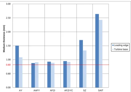
Cheapest common compositions like zircon (SZ) can be used to obtain TiAl castings but about 0.3mm thickness must be removed by some finishing processes like chemical milling.
Best compositions for face coats shells are based on Y2O3 (AY and AAFY). In these cases, if necessary, the thickness to remove will be around 0.2 mm.
A good and economically solution can be obtained using medium price zirconia based face coats (AFZr) which can be improved using some low cost fine yttria not fused (AFZrYC).
Future work must be accomplished in order to confirm grain size influence on permeability and fluidity, study of cooling conditions before remove the castings from the controlled atmosphere furnace, in order to confirm the influence of thermal effect of air on surface hardening of the castings.
To support developing process, computational tools were used within the research group, which entails appropriate numerical models and digital systems. These advances, along with experiments and measurement operations, have speeded up the whole process of development regarding mold architecture.
Lastly, and taking advantage of the knowledge obtained in investment casting of titanium alloys, a methodology for the design and manufacture of custom-fit titanium prostheses based on the medical images manipulation has been developed. The proposed approach for manufacturing metallic prostheses has also been applied with success to produce extra-oral soft-tissue prostheses in silicone.
Keywords: Non-conventional casting processes, Melting and pouring of reactive alloys,
Ceramic formulations, Numerical tools, Custom-fit titanium prostheses, Extra-oral soft-tissue prostheses in silicone.
vii | P a g e
Resumo
Apesar dos enormes benefícios trazidos para a indústria automóvel, aeronáutica e aeroespacial pela introdução de peças e componentes em ligas reativas de titânio e aluminetos de titânio para solicitações a altas temperaturas, o seu processamento é de elevada complexidade e dificuldade.
Neste trabalho, foram desenvolvidos processos inovadores para a fusão e vazamento destas ligas. Estes desenvolvimentos também abordaram o problema da reatividade com carapaças refratárias utilizadas na fundição de precisão de ligas de titânio e aluminetos de titânio, bem como o comportamento reológico dos refratários utilizados no fabrico de carapaças para ligas de níquel.
Neste contexto, novas soluções para a fusão e vazamento de ligas de titânio foram estudadas utilizando inicialmente cadinhos cerâmicos e por último cadinhos frios de fusão por indução. A primeira solução promoveu um elevado sobreaquecimento e um aumento da capacidade de enchimento dos moldes, todavia não garantiu a fusão de ligas de titânio convencionais com uma contaminação aceitável. A segunda solução destinou-se a diminuir o teor de oxigénio nas ligas de titânio causado por reações refratário-metálicas durante a fusão em cadinhos cerâmicas. No entanto, a solução de cadinho frio impôs restrições de sobreaquecimento, o que fez diminuir a capacidade de enchimento. A solução global consistia no desenvolvimento de um sistema utilizando cadinho frio em contra-gravidade com pressão diferencial de vazamento para superar as limitações da espessura.
Além disso, cadinhos cerâmicos para aplicações de fundição de TiAl e outras ligas reativas têm sido investigados, nomeadamente as suas formulações químicas. Em adição, estas ligas (isto é, ligas de Ti e TiAl) são altamente reativas no estado líquido, o que leva à formação de uma camada dura e frágil rica em elementos intersticiais, tais como o oxigénio, na superfície dos produtos fundidos como um resultado da redução química do "face coat" das carapaças cerâmicas por titânio líquido, a chamada α-case. Neste trabalho, foi realizado um amplo estudo das formulações químicas de “face coat” de carapaças cerâmicas para a fundição de uma determinada liga γ-TiAL.
viii | P a g e Contrariamente ao que acontece com as ligas de titânio convencionais, demonstrou-se que os aluminetos de titânio no estado líquido não reagem tanto com barbotinas baseadas em zircão e zircónia.
Relativamente à colabilidade, a melhor capacidade de enchimento das moldações foi obtida para o caso de “face coats” de granulometria mais elevada centrada em ≤200 mesh, provavelmente devido à sua maior permeabilidade.
As soluções económicas de “face coats” de zircão podem ser usadas para a fundição de aluminetos de titânio, mas a camada superficial endurecida de 0,3mm deve ser removida por processos de acabamento como a maquinagem química.
As melhores formulações em termos de reatividade foram conseguidas com carapaças com “face coats” baseados em farinha de ítria, usando com ligantes produtos orgânicos ou misturas com alumina fumada. Neste caso a espessura contaminada a remover será de apenas 0,2mm.
Uma solução razoável e económica consiste na utilização de farinhas de custo médio de zircónia ou zircónia misturada com ítria chinesa (ítria química não fundida de baixo custo).
Devem ser realizados no futuro trabalhos no sentido de confirmar a influência da granulometria das farinhas das cerâmicas do “face coat” na colabilidade das ligas, bem como de confirmar a influência do arrefecimento das peças fundidas fora do forno ao ar no seu endurecimento superficial.
Os desenvolvimentos realizados ao longo deste trabalho foram suportados por ferramentas de apoio baseadas em modelos numéricos e sistemas digitais. Estes métodos computacionais avançados combinados com experiências e operações de medição permitiram acelerar todo o processo de desenvolvimento no que diz respeito à arquitetura das moldações.
Por último, e tendo em conta o conhecimento obtido em fundição de precisão de ligas de titânio, foi desenvolvida uma metodologia para o projeto e fabrico de próteses de titânio à medida, com base na manipulação de imagens médicas. A abordagem proposta
ix | P a g e para o fabrico de próteses metálicas tem igualmente sido aplicada com sucesso no desenvolvimento e produção de próteses de tecidos moles extra-orais em silicone.
Palavras-chave: Processos de fundição não-convencionais, Fusão e vazamento de ligas
reativas, Formulações cerâmicas, Ferramentas numéricas, Próteses de titânio à medida, Próteses de tecidos moles extra-orais em silicone.
xi | P a g e
Table of contents
Acknowledgments ...iii Abstract ...v Resumo ... vii Table of Contents ... xi List of Tables ... xvList of Figures ... xvii
I Introduction ... 1
1. Motivation and Goals ... 3
2. Structure of the thesis ... 7
II Investment casting of reactive alloys ... 9
1. Melting and pouring of reactive alloys ... 11
1.1. Development of melting and pouring processes ... 12
1.1.1. Development and implementation of a ceramic crucible vacuum/controlled atmosphere furnace ... 12
1.1.2. Development and implementation of a cold skull levitation melting and pouring chamber .. 14
1.1.3. Development and implementation of a cold skull melting with contra gravity pouring chamber ... 15
1.1.4. Development of ceramic formulations for reactive alloys ... 16
2. Influence of ceramic shells face coat composition on the reactivity of TiAl castings ... 19
2.1. Introduction ... 21
2.2. Experimental Procedure ... 29
2.3. Results and Discussion ... 34
2.4. Conclusions ... 41
References ... 41
III Enhancement of casting processes using numerical tools and experimental analysis ...45
1. Computational methods for numerical simulation of casting processes ... 47
2. Modelling feeding flow related shrinkage defects in aluminum castings ... 49
2.1. Introduction ... 51
xii | P a g e
2.2.1. Continuum equations ... 52
2.2.2. Numerical method ... 55
2.2.3. Shrinkage defects formation ... 56
2.3. Results and discussion ... 57
2.3.1. Experimental results... 58
2.3.2. Numerical and experimental comparison ... 60
2.4. Conclusions ... 63
References ... 64
3. Numerical and experimental research of γ-TiAl turbine produced by investment casting melted using a vaccum furnace... 65
3.1. Introduction ... 67
3.2. Experimental method ... 69
3.3. Numerical study ... 71
3.3.1. Material ... 71
3.3.2. Initial and boundary conditions ... 71
3.4. Results and Discussion ... 73
3.4.1. Filling sequence of the blade tips ... 73
3.4.2. Shrinkage position of the turbines ... 74
3.4.3. Solidification speed of the different positions of the turbine ... 75
3.4.4. Microstructure of the TiAl alloy under different solidification speed ... 76
3.4.5. Hardness of the different positions of the TiAl turbine ... 77
3.5. Concluding remarks ... 78
References ... 79
IV Design and manufacture of custom-fit prostheses ...81
1. Customized medical prostheses ... 83
2. Digital-based engineering tools for tailored design of medical implants ... 85
2.1. Introduction ... 87
2.2. Methods ... 88
2.1.1. Data acquisition and 3-D reconstruction ... 88
2.1.2. 3-D modelling ... 89
2.1.3. Implant design ... 90
2.3. Demonstrative examples of application ... 90
2.3.1. Case-study 1: Femur fracture ... 90
2.3.2. Case-study 2: Maxillofacial deformity ... 93
2.4. Conclusions ... 94
References ... 95
3. Custom Hip Prostheses by Integrating CAD and Casting Technology ... 97
3.1. Introduction ... 99
3.2. Method ... 99
3.2.1. Images – Mimics and 3-matic Software ... 100
3.2.2. Prototypes – SL Quickcast ... 101
3.2.3. Casting ... 102
3.2.4. Final custom prosthesis ... 103
3.3. Conclusions ... 104
References ... 105
4. A framework for custom design and fabrication of cranio-maxillofacial prostheses using investment casting ... 107 4.1. Introduction ... 109 4.2. Methodology ... 110 4.2.1. Image processing ... 110 4.2.2. Biomodelling ... 111 4.2.3. Fabrication ... 113 4.2.4. Finishing ... 114
xiii | P a g e
4.3. Case studies ... 115
4.3.1. Case-Study I: Craniofacial prosthesis ... 115
4.3.2. Case-Study II: Orbital prosthesis ... 117
4.4. Conclusions ... 118
References ... 119
5. An engineering-based approach for design and fabrication of a customized nasal prothesis ... 121
5.1. Background and aim ... 123
5.2. Technique ... 125
5.2.1. Data acquisition and 3-D reconstruction ... 127
5.2.2. Prosthesis design ... 128
5.2.3. Moulds fabrication and prosthesis manufacturing ... 128
5.2.4. Final fittings ... 129
5.3. Discussion ... 129
5.3.1. Retention system ... 129
5.3.2. Aesthetic outcomes ... 130
5.3.3. Time demands and costs ... 131
5.3.4. Patient satisfaction... 132 5.4. Key points ... 133 References ... 133 V Conclusions ... 135 1. Conclusions ... 137 2. Future Work... 140 VI Publications ... 143 1. Publications ... 145
2. Guidance of Graduation Final Projects ... 147
xv | P a g e
List of Tables
Chapter II
Subchapter 2
Table 2.1 - Properties of several commercial titanium alloys (Titanium Information Group, 2012) Table 2.2 - Ti aluminides and nickel superalloys, HC – compact hexagonal, CCC – body centred cubic, CFC – face centred cubic crystal structures (adapted from Magalhães, 2012)
Table 2.3 - Thermal properties of different ceramic materials (Barrigana, 2013) Table 2.4 – Binders properties.
Table 2.5 – Summary of slurries face coat (FC) composition Table 2.6 –Main properties of the γ-TiAl alloy (Barrigana, 2013). Table 2.7 –Microhardness values (HV) of all samples.
Chapter III
Subchapter 3
Table 3.1 - The composition, liquidus and solidus of the γ-TiAl RNT650 alloy.
Chapter IV
Subchapter 3
Table 3.1 - Time spent to finish a custom hip prosthesis since the DICOM files are available.
Subchapter 5
Table 5.1 Distance measurements and nasal–facial proportion measurement. Table 5.2 Costs and time demands.
xvii | P a g e
List of Figures
Chapter II
Subchapter 2
Figure 2.1 - Main steps of the investment casting process.
Figure 2.2 - Generic composition of a ceramic shell for investment casting. Figure 2.3 - Generic composition of a ceramic shell for investment.
Figure 2.4 - Ellingham diagram for the more common oxide formation occurred in investment casting. Figure 2.5 - Standard test sample machined in an aluminium alloy 7075.
Figure 2.6 - Measurement of reference values for: a) the leading edge of the blades, and b) turbine base. Figure 2.7 - Wax test samples in the tree ready for investment casting.
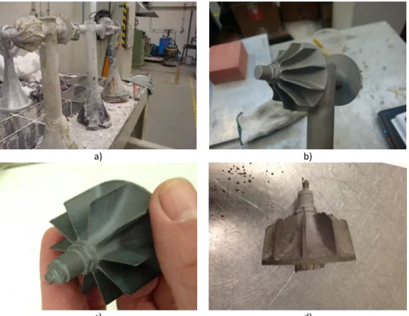
Figure 2.8 - Casted metallic tree: a) after knock-out and b) after corindon blasted; Casted parts: c) complete filling and d) incomplete filling.
Figure 2.9 - Location of samples used in micro hardness and microstructural characterization.
Figure 2.10 - Medium thicknesses of the metallic turbines leading edge and base obtained with different shells slurries face coat composition.
Figure 2.11 - Medium microhardness evolution from the surface to a 1 mm depth of the 6 casting obtained from the shells tested.
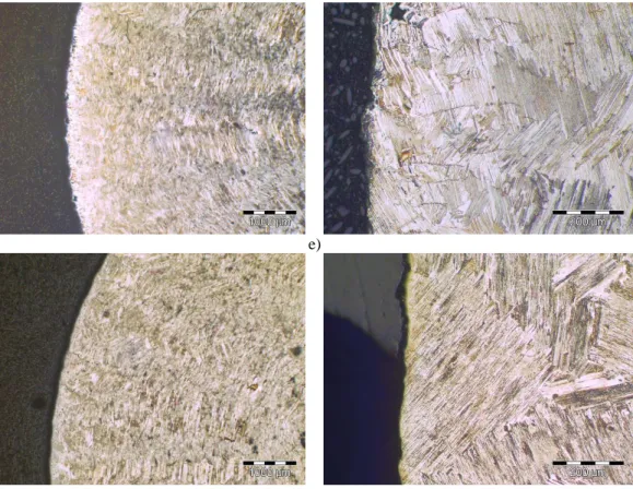
Figure 2.12 - Optical microstructures of the samples produced with the different face coats (see table 2.5 for details): a) AY, b) AAFY, c) AFZr, d) AFZrYC, e) SZ and f) SAIT.
Figure 2.13 - SEM microstructures of the metallic TiAl samples produced with the different face coats with the locations where chemical composition was determined: a) AY, b) AAFY, c) AFZr, d) AFZrYC, e) SZ and f) SAIT.
Chapter III
Subchapter 2
Figure 2.1 - Designed geometry, top view and two sections views A–A and B–B and 3D model. Figure 2.2 - Experimental cooling curve for AlSi12 alloy and AlSi7.
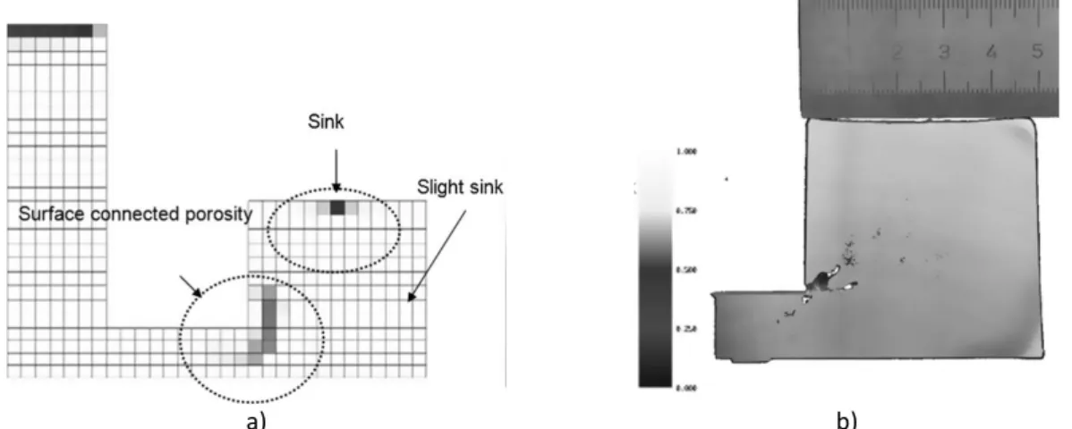
Figure 2.3 - Detail views from 14 mm section, showing the surface sink and surface connected porosity, AlSi7.
Figure 2.4 - Detail views from AlSi12, short freezing, section 14 mm and 18 mm, showing the surface connected porosity.
xviii | P a g e Figure 2.6 - Feeding velocity field and solid fraction for AlSi7 with neck size of 14 mm (a) 25% average solid (b) 40% average solid.
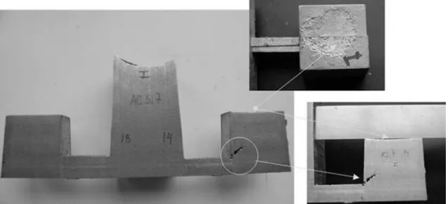
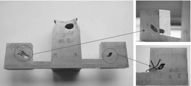
Figure 2.7 - Shrinkage defects distribution for AlSi7 with neck size of 14 mm: (a) simulation (b) experiment. Figure 2.8 - “Caved surfaces” shrinkage defect for AlSi12 neck size 14 mm.
Figure 2.9 - Shrinkage defect for AlSi12 neck size 16 mm and 18 mm. Figure 2.10 - Shrinkage defect for the complete model.
Subchapter 3
Figure 3.1 - Designed turbine: (a) Milled master part and (b) Wax pattern. Figure 3.2 - (a) Wax sprue, (b) Face coat shell after dry and (c) Backup coat shell. Figure 3.3 - Vacuum furnace.
Figure 3.4 - Finite element meshes: (a) turbine, (b) face coat and (c) backup coat.
Figure 3.5 - The filling sequence of the liquid: (a) the bottom tip of the blade and (b) the top tip of the blade.
Figure 3.6 - Velocity and temperature field of pouring process: a) the fluid velocity of the liquid into the turbine; the temperature field of the turbine just after filling.
Figure 3.7 - Shrinkage of the gating system: a) numerical and b) experimental results.
Figure 3.8 - Temperature drop VS time change of the different positions of the turbine. Blade middle (point 1), centre top (point 2), centre middle (point 3), and centre bottom (point 4).
Figure 3.9 - Microstructures at four turbine positions: a) blade (position 1), b) centre top (position 2), c) centre middle (position 3) and, d) centre bottom (position 4).
Figure 3.10 - Hardness of different positions of the turbine- centre part.
Chapter IV
Subchapter 2
Figure 2.1 - MIMICS 16.0 interface: 3-D hip reconstruction. Figure 2.2 - 3-D manipulation for the alignment of sacroiliac joint.
Figure 2.3 - a) 3-D model after image segmentation; b) 3-D model after 3-D manipulation in 3-matic 8.0 (fracture reduction and correct placement/alignment of bone segments).
Figure 2.4 - a) SYNTHES® Locking compression plate. Implant design in 3-matic: b) implant projection onto patient’s anatomy; c) tailored implant system – plate and locking screws.
Figure 2.5 - Prototyped models for pre-validation: a) plate; b) anterior view; c) posterior view. Figure 2.6 - 3-D virtual models: a) cranium; b) prosthesis; c) cranium and prosthesis.
xix | P a g e
Subchapter 3
Figure 3.1- DICOM files treated in Mimics to create an isolated femur mask. Figure 3.2 - STL files from Mimics treated in 3-Matic to study femur cavity. Figure 3.3 - Study developed for a custom hip prosthesis.
Figure 3.4 - Ceramic shell manufacturing; a) Models built using CAD software; b) Sand shower to coat the SL-assembly; c) Burning process to eliminate the resin ashes.
Figure 3.5 - Casting furnace for reactive alloys; a) INEGI furnace apparatus to cast reactive alloys in controlled atmosphere; b) Cold crucible with Ti alloy levitating inside; c) Skull formed after casting. Figure 3.6 - Final prosthesis; a) Portucale prostheses obtained by different processes: on top the casted prosthesis, in the middle machined with a Morse taper and bottom a fully machined prosthesis (not cast); b) X-Rays images of the prosthesis.
Subchapter 4
Figure 4.1 - Mimics® 16.0 interface with the imported DICOM files and 3D model of the case-study I regarding a craniofacial defect.
Figure 4.2 - a) Anatomical model; b) Prosthesis materialized by SL.
Figure 4.3 - a) Wax pattern for investment casting; b) Ceramic shell around the wax pattern. Figure 4.4 - Anatomical model of the case-study I regarding an orbital defect.
Figure 4.5 - Design sequence for creating a cranioplasty prosthesis using 3-matic®: (a) Drawing a curve around the defect, (b) Applying an offset for the prosthesis’ thickness & (c) Trimming the ex-cess material in accordance to the mirrored health side of the cranium.
Figure 4.6 - a) Reconstruction of the 3D model using Mimics® 16.0; b) Custom-fit design prosthesis using 3-matic® 8.0.
Figure 4.7 - a) 3D model reconstructed with visible defective orbital region; b) First version of the designed orbital prosthesis; c) Second version of the prosthesis’ design. All design methodologies were performed using 3-matic® 8.0.
Subchapter 5
Figure 5.1 - Nasal prosthesis’s design and manufacturing steps: (a) 3D reconstruction of patient’s face by CT images, (b) direct face scanning to create a digital nose database, (c) selection and alignment of virtual nose model, (d) surface fitting and trimming of the virtual prosthesis model, (e) smoothing and cutting operations to create functional nostrils on the prosthesis, (f) virtual model of outer mould, (g) plastic model of outer mould, (h) wood box, (i) silicone casting inside the wood box, (j) silicone mould, (k) virtual model of inner mould, (l) plastic model of inner mould, (m) plastic model of inner mould inside the silicone mould, (n) silicone nose prosthesis, (o) silicone nose prosthesis on the prototyped plastic model of the patient’s face, (p) CAD model of the substructure, (q) plastic model of the substructure, (r) CAD assembly of the substructure with the eyeglasses and (s) silicone nose prosthesis with the eyeglasses.
1 | P a g e
I
3 | P a g e
1. Motivation and Goals
Since 2004 the author of this work has been dedicated to the development of non-conventional casting processes for the production of turbocharger components such as aluminium and titanium alloys impellers, titanium aluminides turbines, nickel super alloys for aircraft turbo reactors combustion chamber heat shields and other components in a very close collaboration with the company Zollern & Comandita Portugal (ZCP).
All these studies led to important R&D projects, which consisted in the development of non-conventional processes absent in Portugal and/or with small or none expression in worldwide. Some of these have included an industrial implementation at ZCP. The projects started to be in the area of vacuum and low-pressure counter-gravity casting of aluminium alloys for turbocharger impellers by using hybrid moulds of cooled copper plate and plaster moulds, followed by vacuum/controlled atmosphere casting of titanium alloys, nickel super alloys and finally titanium aluminides.
Among all these R&D projects, the following can be highlighted:
TURBOCAST, FUNDIMP and VABIMP: Development and implementation of aluminium
alloy vacuum and low-pressure counter-gravity casting processes for turbocharger impellers by using moulds, which are in plaster for the impeller fans and in copper cooled plate for the back massive part of the wheels. These processes resulted in a new plant in ZCP. Silicone patterns technology, equipment for casting plaster moulds with vacuum and vibration, striping presses, plaster mould production lines, melting and casting equipment and finally heat treating equipment were developed under the coordination of the author's work and fully manufactured in Portugal both for development and after further improving for industrial applications.
COMTICAST, COMPINTEGRA and HYPERTURB: Development of casting processes for
titanium alloys impellers and nickel alloys and titanium aluminides for turbines. These processes were developed at INEGI and implemented in ZCP that since 2013 is producing nickel alloys components and meanwhile established a laboratory for special ceramic coatings for titanium aluminides process development.
4 | P a g e
AEROVAC: Development and implementation of a casting process for the production of
nickel super alloys heat shields for the combustion chamber of turbo reactors. This process is implemented in ZCP for industrial small scale production.
All these projects began at INEGI with typically 4/5 collaborators from ZCP working at INEGI that afterwards moved to company in order to implement these processes.
TOOLING EDGE and MEDCAST: Development of casting processes for
cranio-maxillofacial, hip and knee prostheses in titanium and cobalt chromium alloys. The casting process of chromium-cobalt alloys for prosthetic knees, whose development has exclusively been made by ZCP, is currently being implemented for industrial production and the development of the casting process of titanium alloys is as well under development centred at INEGI.
As a result of the secrecy that usually characterizes these applied industrial research projects with companies, during this period the author of the work did not publish significative papers, specifically on these issues. However, having arisen from the development of this work several projects and MSc dissertations that were done under the guidance of the author (see list of supervisions of MSc dissertations).
Taking into account the know-how and experimental facilities acquired in the development of casting processes of titanium alloys for turbochargers impellers, the knowledge in silicone processing, titanium casting and investing in a specific software for medical images manipulation an effort was made to extend the scope of applications, namely into the medical field, particularly in development of methodologies for the design and casting of custom-fit prostheses. The developed approach of design and moulds processing for wax injection demonstrated applicability in the manufacture of extra-oral soft tissue silicone prostheses, whose results are also part of this thesis. The main objectives of the work presented throughout this thesis are:
Development of vacuum controlled atmosphere melting and pouring processes for Ti alloys, Ni alloys and TiAl;
5 | P a g e Development of chemical formulations for ceramic moulds and crucibles for
investment casting and induction melting of reactive alloys, such as Ti, Ni and TiAl;
Optimization of mould layouts, rapid tooling and casting processes based on the development of numerical models and experimental validation;
Development of design and manufacture methodologies for the casting of custom-fit titanium prostheses and vacuum casting of silicone for soft-tissue prostheses.
7 | P a g e
2. Structure of the thesis
This PhD thesis is organized in five chapters, namely (I) Introduction, (II) Investment casting of reactive alloys, (III) Enhancement of pouring processes using numerical tools and experimental analysis, (IV) Design and manufacture of custom-fit prostheses and (V) Conclusions.
Chapter I comprises an Introduction to the thesis and it includes the Motivation and Goals of the presented work, as well as the Structure of the thesis.
The main challenges associated with the investment casting of reactive alloys are expressed in Chapter II. This chapter deals with two topics: the development of melting and pouring techniques and the development of ceramic crucibles and ceramic shells formulations. The achieved developments on this last theme are synthetize in a research paper entitled “Influence of ceramic shells face coat composition on the reactivity of TiAl
castings”, which has been submitted to a peer-reviewed journal.
Chapter III focuses on the enhancement of pouring processes using numerical tools and experimental analysis. Within this chapter, the development of computational models and experimental validation approaches for supporting design and casting operations is presented. The outcomes of this study are presented throughout two research papers, which have been submitted to peer-reviewed journals. The first article deals with aluminium alloys and is entitled “Modelling feeding flow shrinkage related defects in
aluminium castings”. The other paper is related to titanium aluminides and is entitled
“Numerical and experimental research of γ-TiAl turbine produced by investment casting
melted using a vacuum furnace”.
Chapter IV describes a methodology for design and manufacture of custom-fit prostheses, as well as some clinical applications. The achieved developments are presented as a set of four articles reported in conference proceedings and scientific publications. The first article is entitled “Digital-based engineering tools for the tailored
design of medical implants” and describes in detail the adopted methodology for the
design of custom-fit implants. The second and third articles present two applications of metallic prostheses, namely an artificial hip stem (in the “Custom hip prostheses by
8 | P a g e
Integrating CAD and casting technology”) and a cranio-maxilofacial prosthesis (in the “A framework for custom design and fabrication of cranio-maxillofacial prostheses using investment casting”). The last research paper reports the application of the developed
methodology of design and manufacture of custom-fit prostheses to the production of soft-tissue prostheses. This article is entitled “An engineering-based approach for design
and fabrication of a customized nasal prosthesis” and describes the production of a
silicone prosthesis of a nose.
Finally, the main conclusions of the present work and some suggestions for future research are expressed in Chapter V.
9 | P a g e
II
11 | P a g e
1. Melting and pouring of reactive alloys
Investment casting of reactive alloys (titanium alloys, titanium aluminides, invar, nickel superalloys, magnesium alloys and cobalt chromium alloys among others) under the vacuum/controlled atmosphere melting and casting conditions, mould layouts and ceramic shells formulations are key variables for success of castings.
Control of the atmosphere of the melting and pouring processes, to minimize the metal atmosphere reactions is a crucial item to ensure minimal contamination of melts as well as the success in filling thin and complex parts using gravity casting and differential pressure casting. In vacuum induction melting (VIM) with ceramic crucibles the formulation and structure of crucibles are determinant for the molten metal contamination among other.
The formulation of the ceramic shell determines the metal refractory reactivity, the thermal shock resistance, permeability, dimensional stability and easy of processing of the moulds. The castings skin, the hot cracking susceptibility is also controlled by the ceramic shells with a significant impact on the properties and costs of the final component.
This chapter is divided in two areas identified above:
Development of melting and pouring processes (Section 2.1)
Development of formulations of the ceramic shells (Section 2.2)
In Section 2.1, a brief summary of the work done is presented as some developments are industrial property of the company Zollern & Comandita Portugal.
In Section 2.2, it is presented a historical overview of the work undertaken, the developments in the chemical formulations of ceramic shells for reactive alloys and a research paper on this topic submitted to a peer-reviewed journal.
12 | P a g e
1.1. Development of melting and pouring processes
The use of conventional titanium alloys and the newer intermetallic titanium aluminides has been noticed as an increasing demand in several engineering fields. These industrial areas recognize the numerous advantages of these alloys that present themselves as the ideal solution for many applications. Despite major markets continue to be elitist as aerospace and medical, new processing methods of these metallic alloys have been studied in order to make these materials accessible to broader applications.
In order to increase the know-how of casting technology for the manufacture of turbocharger impellers in Ti-based alloys, a commitment to investigate and develop a process for the production of components in these materials was performed. The main objective was to develop a ceramic crucible vacuum induction melting and pouring system considering moulds and crucibles, allowing pouring titanium alloy under conditions of low atmospheric contamination with high enough temperatures to facilitate the filling the thin walls of these impellers. Thus, activities of melting and casting in vacuum/controlled atmosphere systems were carried out
1.1.1. Development and implementation of a ceramic
crucible vacuum/controlled atmosphere furnace
Within this subsection it is described the development of a melting and pouring furnace for titanium and other reactive alloys, targeting the production of thin wall components (0.5-0.6 mm thickness). The designed solution is a ceramic crucible vacuum induction melting furnace that uses a power source of 200KW 50KHz with capacity for differential pressure gravity pouring using 2 chambers in the vertical position: a superior fixed melting chamber and a moveable pouring chamber. The moulds are placed in the inferior chamber that is closed for the pouring. Inferior chamber can have the same pressure of the above chamber for simple gravity casting or can have a slightly inferior pressure aiming to achieve differential pressures in order to increase the filling capacity This furnace presents some innovative concepts solutions that are:
13 | P a g e Flexibility in terms of pouring solutions;
High frequency power source with low electromagnetic stirring particularly helpful for low density and very reactive alloys in order to minimize erosion and reactions and metal projections;
System compaction compared with commercial solutions with tilt pouring and big capacities;
High security avoiding danger of water leaks near to melting like with copper crucibles;
High monitoring with records of vacuum evolution in the in two chambers, power, temperature allowing total automatic operation for high repetitively insensible to human errors.
The design of this furnace is described in detail in (Martins, 2008), master dissertation developed under the guidance of the author of this work. The manufacture of furnace structure and double wall vacuum chambers and collectors was produced by the company M. J. Amaral and the instrumentation was assured by INEGI.
This furnace was designed and implemented during 2008 to 2010. For this task, an extensive work had been done targeting the production of ceramic crucibles by means of wax and silicone molds and the development of ceramic formulations with high mechanical strength at high temperatures, high thermal shock strength and high chemical inertia. However, the reactivity problem was not solved and all conventional titanium alloys melted with this system were contaminated with about 0,25% oxygen from ceramics, promoting low ductility to the castings. The great success of this work was discovered later, in 2012, when it was demonstrated that the system worked very well with less reactive titanium aluminides allowing us to have less than 0,1% oxygen in the castings. Another particularity of this furnace was that, unless vacuum pumps, valves and sensors, it was entirely produced in Portugal at company M.J.Amaral, which acquired knowledge and new competences that allow them to supply two furnaces for the company ZCP, which has been working with low operational costs and without any maintenance problems.
14 | P a g e
This furnace has an important and decisive role in the technological progress of INEGI that pushed it for further projects in the field of reactive alloys, such as Compintegra, Tooling Edge, Hyperturb and, recently, Medcast.
Regarding ZCP, its two furnaces are now being used for producing nickel alloys turbo reactors heat shields, waste gate components for turbochargers and Inconel turbines for turbochargers, as well as are being used for the more recent developments on titanium aluminides casting process.
1.1.2. Development and implementation of a cold skull
levitation melting and pouring chamber
After the bad results in terms of melt contamination of the first solution of ceramic crucible melting process, new developments were imposed. The main goal was the development of a new solution using a cold skull induction melting process in order to minimize the oxygen contamination resulted by the chemical reduction and erosion of the ceramic crucible. Because the original design was based on the necessity of futures changes, the modularity allowed us to change the system in about three hours. The cold crucible was acquired to the patent owner, namely the French company CFSYS.
The new version of the furnace encompasses double wall cooled vacuum chambers, which were also produced by the company M.J.Amaral. The design and assembling of this new furnace allows for obtaining castings of conventional Ti6Al4V completely according to the specifications, with an oxygen level bellow to 0.2% and expected limitations of thicker wall thickness when compared to those ones possible using ceramic crucibles.
With this solution and a reasonable operating repetitiveness, INEGI and ZCP were in position to accept new challenges as conditions to develop the casting process of thicker components in Ti6Al4V, namely in Tooling Edge and Medcast projects. This last project aims to provide to the ZCP the possibility to produce titanium and cobalt chromium knee prostheses.
15 | P a g e The design of this furnace is described in detail in (Silva, 2010), master dissertation developed under the guidance of the author of this work.
1.1.3. Development and implementation of a cold skull
melting with contra gravity pouring chamber
Taking into account the limitation of low thickness (from the previous developments) and having as guarantee an acceptable oxygen contamination, new solutions were explored based on the counter gravity process, patented by Hitchiner and Daido. This option was taken being aware since the beginning of the patents existence.
Using available public patents of cold crucibles, the author started a project of developing techniques for manufacturing and repairing cold crucible by means of controlled atmosphere brazing techniques, because no supplier of this kind of components has been identified. Before advancing to the final solution, it was required to solve an important issue, namely the plunging tube for pouring after melting the alloys. This special tube was designed in order to be able to be immerged in a Ti6Al4V melt at high temperatures. The tubes were developed using a maximum refractoriness slurry made of calcia stabilized zirconia binded with fumed alumina stuccoed with alumina sand, and finished with inert yttria slurry. Even though not truly tested, under real conditions, some experiments of plunging at high temperature demonstrated that the designed solution works well. These good outcomes allowed us to go forward on the development of the new furnace with a vacuum aspiration system for the contra gravity casting in order to surpass the anterior limitation of low thickness. The big complexity of this new solution was the movement of the pouring moveable chamber that must go up when the pouring starts. This technical problem was solved by using flexible stainless steel welbows existing in the market for high vacuum applications.
The design of these concepts is described in detail in (Andrade, 2011) and (André, 2011), master dissertations developed under the guidance of the author of this work. Besides, complementary work of support to the design and manufacture was perform by the author and the INEGI team. Due to lack of time, the implementation of this new system
16 | P a g e
was never been done. Indeed, there was no time to rest because of the requests to work in the two previous versions for casting of super alloys and titanium aluminides. Multi-version designs are very interesting concepts, although sometime the field requirements make impossible its practical application. It was concluded that it would have been better to invest in another power source, structure, vacuum pumps and complimentary equipment.
1.1.4. Development of ceramic formulations for reactive
alloys
Even though the benefits brought to the aerospace and automotive industries by the use of titanium alloys and titanium aluminides, such as high strength at high temperatures, the investment casting of these materials is still complex. These alloys reacts with ceramic shells at pouring temperatures, generating a hard and cracked superficial layer rich in interstitial elements (e.g., oxygen) named “α-case”. This contaminated layer, which is the result of the reduction of the ceramic face coat with liquid metal, must be removed by chemical milling in majority of the cases.
The work done in this field began in 2007 considering only the reactivity between the casted metal and the face coat of the shells. These casting experiments were performed at the facilities of IFIMUP (Instituto de Física dos Materiais da Universidade do Porto), because, at that time, INEGI did not have the melting’s facilities currently available. In the beginning of these studies, the ceramic formulations were based on calcia, yttria and magnesia stabilized zirconia slurries binded with ammonium zirconium carbonate, colloidal yttria and zirconia acetate, respectively.
The first outcomes, published in (Duarte, 2008), reported very hard α-case layers. Despite this, the obtained results worked as an extra motivation and a driving force for further developments.
Thus, the work continued with very cheap and fine grain size chemical yttria from China (5€/kg). After the approval of the COMTICAST project in 2008, the well-known fused yttria (150€/kg) were finally purchased from the relevant supplier Treibaker Industrie
17 | P a g e AG. At this moment, the research idea was to concentrate efforts in a really promising solution.
Rui Félix in this MSc thesis (2008), under the supervision of the author of this work, demonstrated by means of casted cranio-maxillofacial prostheses that colloidal silica binder does not work very well with yttria flours, promoting an incontrollable slurry viscosity that increases till the level of complete inefficiency is reached (it is required too much water to compensate the continuous raise of viscosity). Nonetheless, this solution works despite it presents some lack of permeability.
The real solution only appear in 2010 but only for silicone patterns where there are no wax. With this solution of fugitive organic binder, the slurries were fully stable and economic, but they do not support wax melting and infiltrating followed by vaporization in the flash firing process. The bolilerclave technique of dewaxing was tested and not considered as an option because the high tendency for yttria hydrolysis, which must be confirmed in near future since there is still some doubts about this issue. The solution was definitively achieved at the end of 2012, but not reported as it is a property right of ZCP.
Regarding the production of nickel alloy heat shields for turboreactors, the main problem was not the reactivity but the slurry fluidity and rheology. This problem was unsolved for 3 years in Hollenzollern, the mother house of ZCP in Germany, despite the experience and competence of this company. The problem consists of excess of slurry flux inside the intervals between pins (7000 pins of 1 mm diameter x 3 mm length in a 200 x 50 mm plate). This problem was solved by using an abnormal water based high viscosity slurry that is currently being used to produce industrial components. However the resolution of this complex problem was done by means of not one but three solutions: two solutions based on alcoholic hydrolysed triorthoethilsilicate binded slurries and finally the referred one that is environmental friendly. The first two solutions were discarded, because it must be banned from industrial solutions taking into account security and hygiene concerns of alcoholic solvents.
The solutions for these problems were accomplished based on the knowledge acquired by the team of block ceramic moulding and developed during the PhD of Teresa Duarte
18 | P a g e
in 1998 under the help of the author of this work and his knowledge on the influence of grain size distribution and its effect on slurry behaviour. Vibration and vacuum was used in preliminary developments, but after all stages a normal process was defined. This solution is considered an important milestone of the author of this work as the result allows for the entrance of ZCP into the competitive market of aerospace suppliers. Relevant and challenging problems were solved, despite the lack of scientific reports or papers as a result of the impossibility to publish in peer-reviewed journals for sake of confidentiality issues. Indeed, it is very difficult to present an investment casting problem without describing the process conditions and showing the casted confidential products.
Within this chapter, a paper entitled “Influence of ceramic shells face coat composition on the reactivity of TiAl castings” is encompassed (section 2.2). In order to not compromise the confidentiality agreement, only part of the problem is presented. This is not an easy task as some problems and solutions must be hidden. The standardized test specimen was designed in order to simulate simultaneously for the casting of conventional titanium alloys for impellers and titanium aluminides for turbines.
19 | P a g e
Influence of ceramic shells face coat
composition on the reactivity of TiAl
castings
Article submitted to a peer-reviewed journal
21 | P a g e
2. Influence
of
ceramic
shells
face
coat
composition on the reactivity of TiAl castings
2.1. Introduction
Titanium is a low density element (4.5 g/cm3, about 57% of iron) of improved properties with the addition of alloying elements. Some titanium alloys were developed with the aim of reducing or no reacting with the surrounding tissue implants due to an oxide film formed on their surface. The increasing use of this material is mainly due to its relatively low elastic modulus (100 GPa), higher biocompatibility and superior corrosion resistance, when compared to conventional stainless steel or cobalt - chromium alloys employed in medical area. These are attractive features responsible for the introduction of pure titanium (α CpTi), later α+β alloy (Ti6Al4V), also used in aeronautical applications and automobiles, and recently titanium aluminides (Rocha, 2010).
Titanium aluminides (γ-TiAl) are intermetallic alloys (formed by two metals with different crystal structures) whose development was created by the need for materials to work at high temperature applications, such as aerospace or automotive, with good mechanical properties and lighter weight than the common nickel superalloys, which are the mostly used for high temperature environments. Due to their attractive properties, such as high melting point (around 1600 °C), low density (3.9-4.2 g/cm3), high specific strength (0.14 MPa.m3kg-1), high stiffness (100-145 GPa), good oxidation resistance and good creep behaviour at elevated temperatures, these alloys are potential candidates for several applications (Clemens and Smarsly, 2011).
Among the future high temperature applications of greater commercial interest one can include turbines for turbochargers to be used in gasoline direct injection passenger cars and mass production of turbines for diesel engines turbochargers (Tetsui, 2011). They are in competition with nickel superalloys for this practical application, only losing on the cost of raw materials (460 €/kg for commercial gamma titanium aluminide Met PX and 7 €/kg for superalloys) and manufacturing difficulties (Kothari et al., 2012). Nowadays some TiAl alloys can be ordered at about 100 €/kg.
22 | P a g e
As a material that allows service temperatures of about 800 °C (for some turbine applications can withstand temperatures up to 1000 °C, maintaining high mechanical strength in the region of 800 °C), these materials have earned an increasing interest since the 80s (Leyens and Peters, 2003). The main properties of conventional Ti and TiAl alloys are shown in Tables 2.1 and 2.2.
Table 2.1 - Properties of several commercial titanium alloys (Titanium Information Group, 2012).
ASTM
Grade Alloy composition
Tensile strength min. (MPa) Yield strength min. (MPa) Young modulus (GPa) 4 Pure Ti 550 480 105 5 Ti-6Al-4V 895 825 114 6 Ti-5Al-2,5Sn 825 795 110 20 Ti-3Al-8V-6Cr-4Zr-4Mo (Beta C) aged 1170 1105 102
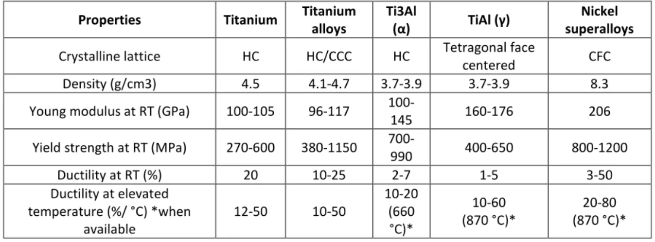
Table 2.2 - Ti aluminides and nickel superalloys, HC – compact hexagonal, CCC – body centred cubic, CFC – face centred cubic crystal structures (adapted from Magalhães, 2012).
Properties Titanium Titanium alloys
Ti3Al
(α) TiAl (γ)
Nickel superalloys
Crystalline lattice HC HC/CCC HC Tetragonal face
centered CFC
Density (g/cm3) 4.5 4.1-4.7 3.7-3.9 3.7-3.9 8.3 Young modulus at RT (GPa) 100-105 96-117
100-145 160-176 206
Yield strength at RT (MPa) 270-600 380-1150
700-990 400-650 800-1200 Ductility at RT (%) 20 10-25 2-7 1-5 3-50 Ductility at elevated temperature (%/ °C) *when available 12-50 10-50 10-20 (660 °C)* 10-60 (870 °C)* 20-80 (870 °C)*
From the analysis of Tables 2.1 and 2.2 it can be concluded that the major disadvantages of titanium aluminides are the reduced ductility, derived from the small number of intermetallic slip systems of the crystal structure (tetragonal face centred), and the low yield strength (400-650 MPa). One way to improve the ductility is through the addition of alloying elements that increase the number of slip systems (Magalhães, 2012).
Precision casting, lost wax and investment casting are synonyms given to the foundry manufacturing process that can produce parts of complex shapes difficult to obtain by machining processes (Sopcak, 1986). Figure 2.1 shows a schematic summary of the investment casting process that can be described as follows:
23 | P a g e 1. CNC machining of a mould for wax injection. Alternatively it can be created
a CNC machined or additive manufacturing model, and obtain a mould to produce the model in wax by filled resin casting;
2. Injection of a wax model with the final shape of the part (compensated with the shrinkage);
3. Construction of a "tree" of models with wax (including feeding and gating systems);
4. Coating the "tree" with a suitable refractory slurry which will resist to high temperatures and reproduce every detail of the model. This part of the process involves dipping into a slurry, subsequent stuccoing with ceramic particles and drying, and repeat this operation until a shell with an adequate thickness is obtained;
5. Flash firing of the wax model: the whole model and shell are heated to temperatures that cause wax melting, leaving a "negative" in refractory material;
6. Sintering the shell at elevated temperature, if necessary, giving it the best properties for casting, and pre - heating the shell;
7. Pouring the metal into the shell, using the selected casting technique; 8. Solidification, cooling and knock-out of the shell, followed by cutting the
gating and feeding system; 9. Finishing the part.
24 | P a g e
Figure 2.1 - Main steps of the investment casting process.
The ceramic shells used in investment casting are made by sequential application of ceramic coatings. Each coating is a thin layer of ceramic slurry (ceramic flours, for example ≤ 74μm (≤ 200 mesh), with a binder), followed by stuccoing with a shower fine particles (for example 125-250 μm). Figure 2.2 shows a possible composition of a ceramic shell, and Figure 2.3 exhibits the relative position of the materials in the shell. It is important to note that the backup layers follow the same manufacture procedure as those of face coat, but with changes in the composition and stucco particle size, using cheaper and coarser ceramic materials.
25 | P a g e Figure 2.2 - Generic composition of a ceramic shell for investment casting.
Figure 2.3 - Generic composition of a ceramic shell for investment.
Due to the nature of the casted alloy, some aspects must be considered when defining the constitution of a successful ceramic shell (Pattnaik et al., 2012):
26 | P a g e
1. Green strength to ensure wax removal by heating without warping, destroying or loosing properties;
2. Strength to withstand the metalostatic pressure of casted alloy; 3. Resistance to thermal shock to avoid fracture during casting; 4. Chemical inertia to avoid reduction of the metal;
5. Permeability to allow air to escape through the walls during pouring of the molten metal;
6. Collapsibility to avoid cracking of components during cooling (Jones and Yuan, 2003);
7. Thermal conductivity to keep uniform heat transfer and adequate cooling through the metal walls.
In order to be able to obtain shells which meet the highest possible number of the previously mentioned requirements, the choice of ceramic materials must be focused on the following (Felix, 2008):
Free energy of formation;
Melting / softening temperature;
Thermal properties;
Availability / cost.
Traditionally, refractories for casting titanium alloys and titanium aluminides are zircon (ZrSiO4), alumina (Al2O3), calcia (CaO), magnesia (MgO), stabilized zirconia (ZrO2-X, X being other compound) and yttria (Y2O3). With non-reactive alloys, vitreous silica (SiO2) and aluminosilicates are also used (Guntlin et al., 2012).
One of the major challenges/difficulties in lost wax casting of titanium and titanium aluminides is their high reactivity in the liquid state with the ceramic shells. Figure 2.4 presents a summary of the Ellingham diagram for oxides suitable to be used as face coat in investment casting. All oxides (MgO, CaO and Y2O3) below the Ti-TiO2 line, at the casting temperatures about 1400 – 1500 °C are potential candidates.
27 | P a g e Standard free Gibbs energy formation ΔG° (kJ/mol)
Temperature (ºC)
Figure 2.4 - Ellingham diagram for the more common oxide formation occurred in investment casting (Turkdogan 1980).
Table 2.3 presents the main thermal properties of the different ceramics used in shells and presented in Figure 2.4.
Table 2.3 - Thermal properties of different ceramic materials (Barrigana, 2013).
Ceramic Thermal expansion coefficient (x 10-6K-1) 20-1000 °C Thermal conductivity (Wm-1 K-1) 20-26 °C
Free Gibbs energy formation, ΔGO (kJ/mol O2) Softening temperature (°C) Zirconia – ZrO2 10.0 2.5 -743 (a 1900 K) 2010 Yttria – Y2O3 8.1 8.0 – 12.0 -989 (a 1469 K) 1855 Alumina – Al2O3 8.0 28.0 – 35.0 -711 (a 1900 K) 1540 Silica – SiO2 0.5 – 0.8 1.2 – 1.4 -610 (a 1685 K) 1280 Magnesia - MgO 9.0 – 12.0 30.0 – 60.0 -684 (a 1900 K) 2100 Calcia - CaO 15.2 30.0 -899 (a 1756 K) 1950 Zircon - ZrSiO4 4.5 8.0 - 1815
The melting temperature of the titanium aluminides (γ-TiAl), 1460-1500 °C (Appel et al., 2011), determines the temperature range to analyse in Ellingham diagram (see Figure 2.4) and compare the free energy of oxides formation. As shown in Figure 2.4, the lines related to the free energy of oxide formation in the lower part of the diagram means that the reaction is thermodynamically more stable.
28 | P a g e
With a softening temperature of 1855 °C, above the melting temperature of the alloy TiAl and larger Gibbs Free energy than all oxides that could be used in the ceramic shells (-989 kJmol-1 at 1469 K), yttria is undoubtedly the most promising refractory material for face coat in terms of reactivity. Its use in ceramic shells only began to be more common in the last 15 years because, despite its potential, there were enormous difficulties in producing an yttria-based slurries which did not gelify prematurely, preventing parts production in large series. In 1993, Horton used successfully face coat yttria slurries, applying colloidal silica as a binder and with the addition of hydroxide ions. This procedure avoided premature gelling of the slurry (Pattnaik et al., 2012).
Different combinations of binders, flours particle size and manufacturing techniques have conducted to the current state of art of ceramic shells, where yttria is the ideal ceramic with the lowest reactivity, as described by Altindis et al. (2011).
Guntlin et al. (2012) studying the "investment casting" of titanium aluminides, claims an Y2O3 formulation face coat and Al2O3 as a successful back-up, with minimal oxygen contamination (300 to 500 ppm by weight), in shells and crucibles for VIM (vacuum induction melting). They refer the existence of fused yttria due to a reaction - dissolution process of the face coat with the liquid metal, but the effect of the presence of yttrium inside the part was not studied. Duarte et al. (2008) also concluded that yttria face coats result in almost no “α-case” presence in Ti6Al4V casts.
However, as suggested by Altindis et al. (2011), for industrial use in investment casting, further research is still demanded to improve the stability and longevity of yttria ceramic slurries and thereby improve the mechanical strength and inertia of the shells.
Yttria slurries in industrial environment are still a concern due to the availability/cost. China is the rare earths largest exporter of todays’ world. The exploitation of resources in the early '80s and the opening of frontiers to the exportations led many countries (India, Brazil, South Africa and USA) who extracted rare earths, to cease this activity because they were unable to compete with the prices and abundance of Chinese resources. Since the beginning of the XXI century, China decreased the extraction of rare earths, mainly by environmental causes, increasing prices and forcing consumers to find alternatives to rare earths (Voigt, 2012).
29 | P a g e Researchers worldwide are currently focused on developing alternative cheaper ceramic formulations with similar or lower reactivity than the yttria ones. In 2012, Cheng et al., published the article "Formation Mechanism of “α-case” on Titanium Investment Cast Parts", where they not only further study the “α-case” formation mechanism, but also proposed a slurry formulation with titanium powder. Cheng et al. (2012) refer the difficulties of working with a slurry prone to premature gelling and containing an expensive oxide such as yttria. So, the new goal is the development of a stable face coat slurry, with a long life, minimum cost and a reasonably chemical inertia with titanium aluminides (Cheng et al., 2012).
The ceramic slurry usually consists of a major portion of highly refractory materials with a binder. The role of binder is providing a link among the refractory ceramic particles and promoting enough strength to withstand the mechanical and thermal stresses during the shell preparation and use. Basically, there are two natures and two types of binders used in investment casting (Pattnaik et al., 2012):
Aqueous dispersions (inorganic nature) colloidal solutions such as colloidal silica, colloidal zirconia, colloidal yttria and colloidal fumed alumina (nano-sized solid particles in aqueous phase);
Alcoholic dispersions (inorganic nature) such as ethyl silicate;
Polymeric dispersions (organic nature) such as acrylate polymers;
Hybrid nature dispersions: mixing dispersions of organic and inorganics (such as zirconium acetate modified with polyacrylamide polymer) (Chen et al., 2011).
2.2. Experimental Procedure
Although the literature is abundant relative to standard test samples for investment casting, experimental work with thin sections parts with complex geometries are uncommon. In this work, the experimental studies were conducted considering the necessity to simulate simultaneously both turbines and impellers turbochargers manufacturing process. The standard test sample designed by us for this work was
30 | P a g e
machined in an aluminium alloy 7075 (see Figure 2.5) and it measures about 40 mm (diameter). This part was used to obtain a resin filled with aluminium powder mould for wax injection. The wax was injected at 68-70 ºC with a 6 bar pressure, using a release agent without silicone to prevent silicon contamination.
Leading edge
Base
Figure 2.5 - Standard test sample machined in an aluminium alloy 7075.
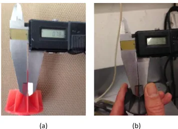
The leading edge of the wax turbine blade were measured with a digital calliper to control dimensional variations during the whole manufacturing process (wax and final metallic part). Figure 2.6 shows measurements in these two parts.
(a) (b)
Figure 2.6 - Measurement of reference values for: a) the leading edge of the blades, and b) turbine base. The wax parts were welded in a tree (gating and feeding system) for investment casting (see Figure 2.7).
31 | P a g e Standard test part Gatting and feeding systems Basin
Figure 2.7 - Wax test samples in the tree ready for investment casting.
After this step, shells with different compositions were manufactured using the materials indicated in Tables 2.4 and 2.5. Each tree was degreased, washed in water and dried. Then they were dipped in the slurry during 30 s, air drying for 1 minute and stuccoed in a rain fall during 10 s. This sequence was repeated twice, to create the face coat.
The backup was done using 5 layers of fumed alumina binder, alumina flour and alumina stucco, or silica binder, zircon flour (or fused silica) and aluminosilicates stucco (Duarte
et al., 2009).
Table 2.4 – Binders properties.
Organic Fumed Alumina Colloidal Silica
Reference A AF S
Type and binder nature Polymeric dispersion, organic nature Aqueous dispersion, inorganic nature Aqueous dispersion, inorganic nature Solids content (%) 47 40 - Al2O3 30 - SiO2 Density (g/cm3) 1.06 1.39 1.21 Medium size of
aggregates (μm) Not available 0.08 0-0.10 Cost (€/kg) 2.5 18.0 5.0
Table 2.5 – Summary of slurries face coat (FC) composition.
Binders Flours Stucco
AY A 50% fused yttria - ≤ 200 mesh and 50% fused yttria - ≤ 325 mesh
yttria 125-250 μm AAFY A+AF Fused yttria - ≤ 200 mesh yttria 125-250 μm
AFZr AF 6% yttria stabilized zirconia - ≤200 mesh 4% CaO stabilized zirconia - 150-300 μm AFZrYC AF 6% yttria stabilized zirconia - ≤ 200 mesh, and 10% 4% CaO stabilized zirconia -