RESEARCH
Open Access
Combination of a geolocation database access
with infrastructure sensing in TV bands
Rogério Dionísio
1,2*, Jorge Ribeiro
2, Paulo Marques
2,1and Jonathan Rodriguez
2Abstract
This paper describes the implementation and the technical specifications of a geolocation database assisted by a spectrum-monitoring outdoor network. The geolocation database is populated according to Electronic
Communications Committee (ECC) report 186 methodology. The application programming interface (API) between the sensor network and the geolocation database implements an effective and secure connection to successfully gather sensing data and sends it to the geolocation database for post-processing. On the other hand, the testbed allows authorized TV white space devices to gain access to the services of the geolocation database, according to a draft implementation of Internet Engineering Task Force (IETF) Protocol to Access White Space (PAWS) Two experimental methodologies are available with the testbed: one focused on coexistence studies with commercial wireless microphones, when the testbed is used for sensing only, and another for demonstration purposes, when the testbed is also used to emulate wireless microphone signals. Overall, this hybrid approach is a promising solution for the effective use of TV white spaces and for the coexistence with digital TV broadcast signals, or dynamic incumbent systems, such as unregistered wireless microphones.
Keywords: Cognitive radio; TV white spaces; Sensor network; Testbed; Geolocation database 1 Introduction
TV white space (TVWS) frequencies are becoming a real world test laboratory of spectrum sharing. However, a cognitive white space device (WSD) operation within the ultra high frequency (UHF) bands may be permitted if (and only if) it does not interfere with incumbent services, such as digital TV broadcast and Programme Making and Special Events (PMSE) services, e.g., wireless micro-phone systems [1]. WSDs should either sense the presence of other signals or make use of a geolocation database to determine which spectrum is unused in the vicinity. Recent studies have shown that the sensitivity of these WSD receivers needs to be very high in order to detect these spectral opportunities effectively, and indeed this task is difficult to accomplish with the existing mobile technology [2].
*Correspondence: [email protected]
1Escola Superior de Tecnologia, Avenida do Empresario, 6000-767 Castelo Branco, Portugal
2Instituto de Telecomunicações, Campus de Santiago, 3810-193 Aveiro, Portugal
In the US, the Federal Communications Commission (FCC) ruling [3] has obviated mandatory spectrum sens-ing in white space networks. Instead, the rulsens-ing requires WSDs to find spectrum opportunities at their respective locations from a central database. Meanwhile, database administrators have been appointed by the FCC, and early services to help identify white spaces have been launched by Spectrum Bridge [4]. In the UK, Ofcom in its public consultation process is supporting geolocation database for WSDs, and the first trials in UK are planned to occur in 2014 [5]. In Finland, the telecom regulator FICORA issued a geolocation database service test license for TV white spaces to Fairspectrum [6].
Although these global regulatory initiatives drive towards the geolocation database solution, sensing is not completely discarded as a long-term option for cognitive radio. At the European level, the operational and struc-ture of the database is not yet defined, but the Electronic Communications Committee (ECC) defend a solution based on the joint application of sensing and databases, harnessing the benefits from both approaches [2]. In par-ticular, a geolocation database assisted by a spectrum © 2014 Dionisio et al.; licensee Springer. This is an Open Access article distributed under the terms of the Creative Commons Attribution License (http://creativecommons.org/licenses/by/4.0), which permits unrestricted use, distribution, and reproduction in any medium, provided the original work is properly credited.
monitoring network is a promising solution for the effec-tive use of white spaces and for successful coexistence with dynamic incumbent systems, such as wireless micro-phones that are not registered in the database. However, until now there has been no single initiative to conduct white space trials experimenting with this hybrid solution. Other approaches combine a geolocation database with sensing carried on the portable WSD [7,8]; however, the hidden node problem may occur and reduce the reliability of the system. The objective of this work is to showcase the implementation of such an approach from the FP7-CREW (CREW-TV) project [9].
This paper is structured as follows. After the introduc-tion in Secintroduc-tion 1, we describe the system architecture in Section 2, the testbed network in Section 3, the communi-cation protocols in Section 4, and the database population process in Section 5. Furthermore, we present the experi-mental methodology in Section 6 with performance eval-uation of sensor nodes. Finally, the demo is presented in Section 7, and conclusions are drawn in Section 8. 2 System architecture
Figure 1 represents the block diagram of the demonstra-tion platform. The rightmost side shows the diagram of the LOG-a-TEC sensor network, one of the open test plat-forms from the CREW testbed federation [9]. Located in Slovenia, this network is an outdoor heterogeneous
ISM/TVWS testbed that can be accessed and config-ured remotely through the Internet with an application programming interface (API). Spectrum sensing is imple-mented on a versatile sensor node (VESNA), which is a hardware platform with a high processing capability and flexible radio. It supports a broad range of sensors and signal generators for the UHF band, while its mod-ular approach allows adaptation to diverse application requirements. On the center of the diagram, the geolo-cation database stores spectral opportunities in a TVWS band. On the leftmost side, a TVWS system may access the geolocation database, using a communication proto-col inspired from Internet Engineering Task Force (IETF) Protocol to Access White Space (PAWS) [10], and request for spectral opportunities to operate on a specific location, time, and duration.
3 LOG-a-TEC: an infrastructured sensor network The core of the LOG-a-TEC testbed consists of a sen-sor network containing approximately 50 low-cost nodes mounted on public lighting infrastructure, distributed between two clusters: one in Logatec city center and the other in the industrial zone. Each VESNA node is installed with omnidirectional antennas on a light pole at 10 m in height and communicates with a coordinator node using ZigBee communication module at 868 MHz. The relative distance between each VESNA node ranges from 60 m
Internet ZigBee network Java API Internet HTTP server TVWS database
Log-a-Tec sensor network
PAWS protocol VESNA sensor node n VESNA sensor node 1
...
SSL SSL HTTPS server VESNA gateway coordinator wireless microphone TVWS link Master WSD Slave WSDup to 600 m, with different propagation loss scenarios between them. With IP connectivity, they can be remotely reprogrammed according to the needs of the investigated use case. Each node hosts a GPS module providing inter-nal geolocation and precise reference timing capability. For storing large sets of data, it also incorporates a mini SD card up to 32 GB of memory [11].
4 Communication protocols
4.1 Communication between the geolocation database and WSDs
The communication with the geolocation database is based on a protocol inspired from IETF PAWS [10]. The main objective of this protocol is to allow a WSD to request spectrum from the geolocation database and retrieve a list of available channel to operate as a sec-ondary user, as shown in Figure 1. The PAWS protocol is currently an internet-draft (version 14) and still under development.
The services are accessed by the master WSD using GET and PUT requests over the Internet. Operations are only initiated by the WSD, with a response from the geolocation database. This eliminates the necessity of the geolocation database to initiate communications with the WSD. We defined separate requirements for slave WSDs and master WSDs. The protocol enables a master WSD to complete the following tasks:
• Connect to the database; • Register with the database;
• Provide its geolocation and other data to the database; • Receive in response to the query a list of currently
available white space channels, maximum power, and sensing requirements.
Moreover, the protocol also enables a slave WSD to complete the following tasks:
• Request to a master WSD, to verify if the slave WSD ID is valid (enrolled in the database);
• Receive in response to the query, a status code from the master WSD, indicating if the slave WSD is valid or not.
Services not considered in the current implementation, but defined in IETF PAWS, are the database discovery and master (or slave) WSDs enrollment in the database.
The contents of the queries and response from the pro-tocol need to be specified. A data model is required which enables the WSD to query the database while including all the relevant information such as geolocation, power char-acteristics, sensing capabilities, etc., which may be coun-try, spectrum, and regulatory dependent. Partially follow-ing an IETF proposal [10], but adapted to the CREW-TV project, the implemented geolocation database is able to
interpret the data model and respond to the queries using the same data model that is understood by all WSDs.
The application protocol utilizes the following proto-col stack for communication between the geolocation database and a master WSD:
• Application layer (HTTPS); • Presentation layer (XML); • Session layer (Undefined); • Transport layer (TCP); • Network layer (IP); • Data link (Undefined); • Physical layer (Undefined).
Several programming languages, from PHP and JavaScript, were used to develop this implementation of the protocol. MySQL is the technology used to implement all the requirements for the database: to store geolocation data, information about all Master WSDs (registration process), and the Slave WSDs (serial number only). In this context, the main objective of PHP is to access a MySQL database, where the TVWS geolocated data is stored. JavaScript language is used to control the user web interface and the Google Map API.
Three services are defined on the interface between the geolocation database and WSDs:
• Service 1: Registration; • Service 2: Channel list request; • Service 3: ID verification.
The services are listed in order, representing the steps that a WSD must take to obtain service from the geolo-cation database. Several timers are also implemented and used by the protocol, during operation:
• Channel list refresh period (CLRP): 1,440 min; • Channel list request timer (CRT): 5 s;
• ID verification request timer (VRT): 5 s; • Registration valid period (RVP): 90 days.
4.2 Communication between the geolocation database and LOG-a-TEC
This section describes the API developed to enable a reliable communication channel between the geolocation TVWS database and the LOG-a-TEC sensor network. This API is used to collect sensing information from the testbed area, on wireless microphone activity, and later used to compute exclusion areas on the geoloca-tion database. We based the communicageoloca-tion on a custom protocol, which is abstracted by a proxy server based on standard HTTPS protocol. This section also reports on the operational sequence to obtain sensing data from the LOG-a-TEC sensor network nodes, using a specification and description language (SDL) diagram.
4.2.1 SDL of the sensing request process
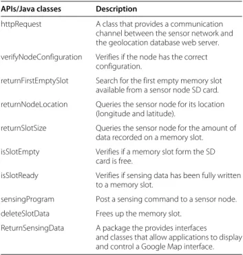
The flowchart diagram presented in Figure 2 gives the operation sequence to gather sensing data from a VESNA node. Each numbered block on the flowchart diagram is associated with the corresponding object/method/class from the API described in Table 1:
1. The user selects the cluster (industrial zone or city center) and the nodes from where the sensing campaign will take place, the sensing time for each node, and the periodicity of the sensing process and triggers the communication between the geolocation database web server and the LOG-a-TEC sensor network. The Java class httpRequest implement HTTPS POST and GET methods for a
request-response protocol between the geolocation database (server) and the LOG-a-TEC network (client) during the sensing process.
2. Each sensor node is requested to send its
configuration parameters, such as the device number, the configuration number, the maximum sensing frequency span, the minimum frequency step, and the minimum sensing time. The information returned is the response from a GET request. 3. Each sensor node is requested to send its storage
availability (available memory slot ID number). The information returned is the response from a GET request.
4. The sensing parameters (starting channel, channel step, last sensed channel) are computed based on the configuration parameters of the sensor node and according to the specificity of the signal to be detected, e.g., wireless microphones. A POST request is sent to each node to proceed with sensing
measurements. Periodically, the application verifies if sensing data storage is complete.
Verify configuration of the VESNA nodes
Verify storage availability of the VESNA nodes
Initiate sensing procedure with the VESNA nodes
Retreive sensing results from SD card Start local CREW-TV services verifyNodeConfiguration returnFirstEmptySlot returnSlotSize isSlotEmpty isSlotReady sensingProgram deleteSlotData ReturnSensingData 1 2 3 4 5 httpRequest
Table 1 A subset of the most relevant classes and APIs used in the communication protocol application APIs/Java classes Description
httpRequest A class that provides a communication channel between the sensor network and the geolocation database web server. verifyNodeConfiguration Verifies if the node has the correct
configuration.
returnFirstEmptySlot Search for the first empty memory slot available from a sensor node SD card. returnNodeLocation Queries the sensor node for its location
(longitude and latitude).
returnSlotSize Queries the sensor node for the amount of data recorded on a memory slot. isSlotEmpty Verifies if a memory slot form the SD
card is free.
isSlotReady Verifies if sensing data has been fully written to a memory slot.
sensingProgram Post a sensing command to a sensor node. deleteSlotData Frees up the memory slot.
ReturnSensingData A package the provides interfaces
and classes that allow applications to display and control a Google Map interface.
5. Sensing data is retrieved from each node with a GET request. The time stamp and power measurements are read in chunks of 512 bytes, according to the specification described in [3]. Subsequently, the information is deleted and the memory slots are ready to store the results from the next sensing measurements.
5 Geolocation database
TVWS devices, according to CEPT report 24 [1], are allowed to operate on a ‘non-interfering, non-protected basis’. Several means were discussed in several interna-tional forums [12-14] to cope with this non-interfering demand, among them are sensing and geolocation. For the geolocation scenario (with or without sensing), besides the equipment for the WSD to locate its own position, a database is required that provides data on acceptable transmit power for the possible channels at the requested location and time. This section describes how to calculate the data, i.e., the acceptable transmit power for the WSD. 5.1 Procedure to calculate WSD transmit power
In order to estimate the maximum transmission power of TVWS devices in the UHF bands, a methodology aspect has to be considered. The methodology used to com-pute TVWS maps, i.e., the maximum acceptable transmit power for a given location and TV channel, follows ECC report 186 [15] directives, as presented on the diagram of Figure 3.
For each spatial unit (x, y), and for each digital video broadcast (DVB-T) channel ch, the wanted sig-nal strengths E(x, y) and location probabilities q(x, y) can be calculated with a DVB-T coverage calculation soft-ware. Location probability describes the probability that a broadcast reception is possible at a given location:
q = Pb ! PS≥ PS,min+ K " i=1 rUk · PUk # (1) Pb{A} is the probability of event A, PS is the received power of the wanted DVB-T signal, PS,min is the DVB-T receivers (noise limited) reference sensitivity level, PUk is
the received power of the kth unwanted DVB-T signal, and rUk is the DVB-T-to-DVB-T protection ratio for the
kth DVB-T interferer [15]. 5.1.1 Nuisance field
From the input data (q(x, y) and E(x, y)), the total nui-sance field U(x, y) can be determined. The nuinui-sance field describes the acceptable interference level of the WSD at the location of a broadcast reception antenna, compris-ing of noise (N) plus a minimum signal to noise ratio (SNR) and the unwanted signal contributions (NUDVB-T)
from other DVB-T transmitters:
UdBm= (N +SNR)⊕NUDVB-T1⊕NUDVB-T2⊕. . .⊕NUDVB-Tn
(2) All variables in Equation 2 are represented in a loga-rithmic scale. The symbol ⊕ represent a sum in the linear domain, whereas + is a sum on a logarithmic scale. If, at a given location a somewhat lower location probabil-ity (q → q − !q) can be accepted, then the nuisance field can raise, giving the opportunity to operate a further interfering device (NUWSD):
UdBm′ = (N +SNR)⊕NUDVB-T1⊕NUDVB-T2⊕. . .⊕NUWSD
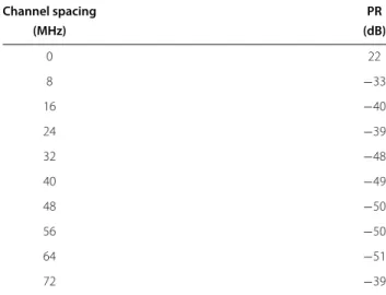
(3) So, with the knowledge of wanted signal strength PS, location probability q and the specification of acceptable degradation !q for each location (x, y) and channel ch, the WSD nuisance field can be determined. However, this is not necessarily the location of the TVWS device or the channel at which the TVWS device is transmitting. In fact, in most of the cases, the channel will be different. ECC report 148 [16] provides protection ratios for co-channel and adjacent channel operation and overload threshold to relate WSD operation in channel ch′with broadcast recep-tion in channel ch. As this report only gives ranges for some parameters, Table 2 represents the average parame-ters which were chosen for this investigation. For channel
Methodology ECC 186 Radio frequency planning tool E(x,y) q(x,y) Constraint
Fixed / mobile TV broadcast Fixed TVWS BS Mobile TVWS UE Scenarios Parameters ECC 148 Assumptions Pwsd(u,v) Maximum EIRP Nuisance power (x,y) Protection Ratio q degradation Coverage maps
Figure 3 TVWS computation methodology [2].
Table 2 Protection ratio of DVB-T receiver for fixed reception, as a function of channel spacing
Channel spacing PR (MHz) (dB) 0 22 8 −33 16 −40 24 −39 32 −48 40 −49 48 −50 56 −50 64 −51 72 −39
spacing ch − ch′up to 64 MHz (8 DVB-T channels), the protection ratios are assumed symmetrically. For 72 MHz channel spacing (9 DVB-T channels), the intermediate fre-quency (IF) effect on the DVB-T receivers may cause a poor value (−39 dBm). If this is the case, it is only used at one side, whereas for ch − ch′ = −72 MHz, the value for ch − ch′ = 64 MHz is used if it is better than the value for ch − ch′ = 72 MHz. For simplicity, we consider that WSD maximum equivalent isotropically radiated power (EIRP) is limited to 30 dBm to avoid overloading of DVB-T receivers [2].
5.1.2 Reference geometry and scenarios
As a next step, the relative distance and signal propagation between the location of a WSD and the possible loca-tion of a DVB-T receiver must be considered. Following the proposed methodology from [15], in order to find the maximum permissible power of a WSD at pixel (u, v), we define a circular area of interest around it, as shown in Figure 4. The radius of this area is a function of the output
Figure 4 Definition of co-, adjacent, and unaffected pixels. The circle represents the limit of the coverage area of the WSD.
power of the WSD. For a WSD with maximum EIRP of 30 dBm, limited by the overload threshold on the DVB-T receiver, a radius of 30 km is adequate [15]. DVB-The pixels outside the circle are assumed to be unaffected from the WSD. When we consider adjacent channel interference, the radius will be significantly smaller. Given that the dif-ference in the protection ratios can be up to 73 dB, as indicated in Table 2, the radius should be 10 to 15 times smaller, and it was set to 1.5 km.
If the DVB-T receiver and the WSD are in the same pixel, we have no information on their separation, so the co-pixel computation needs to be based on a refer-ence geometry. For this study, we consider a fixed DVB-T reception and a fixed TVWS BS transmission, both with outdoor aerial antennas at 10 m in height [15], with a min-imum separation distance of 20 m, following the reference geometry defined in [17]. According to a free-space path loss (FSPL) propagation model, minimum path loss for the frequency range of interest (470 to 790 MHz) is roughly −50 dB. To account for the potential inaccuracies (or estimation errors) in the location of a WSD or DVB-T receiver within a pixel, the above minimum path loss within a pixel is specified as the minimum of those cal-culated for the M surrounding pixels, i.e., the 8 first-tier adjacent pixels (M = 8), as illustrated in Figure 4. This approach also accounts for the case where a WSD within a pixel is actually in the proximity of a DVB-T receiver in a neighboring pixel.
As indicated in Table 3, four possible scenarios describe the possible arrangements of TVWS transmitter and DVB-T receiving antenna. With realistic assumptions on minimum distance and by applying appropriate propa-gation models, the propapropa-gation loss can be determined. As the distances are usually short, typically less than a few kilometers, simple propagation models, like ITU-R P.1546-4 [18] or extended Hata [19], that do not take into account topology can be used. For distances from 10 m to 10 km, these models are comparable to an even more
Table 3 WSD to DVB-T receiver coupling possibilities [15]
Co-channel Adjacent channel
Co-pixel Scenario A: no transmission Scenario B: reference geometry
Adjacent pixel Scenario C: apply a propagation model and use co-channel protection ratios
Scenario D: apply a propagation model and use adjacent channel protection ratios
simple model, based on FSPL, with the following profile [20]: loss(d, ch′) dB= ⎧ ⎪ ⎪ ⎪ ⎪ ⎪ ⎨ ⎪ ⎪ ⎪ ⎪ ⎪ ⎩ FSPL(d, ch′) , d < 100 m FSPL(d, ch′)− 10 dB/decade , 100 m ≤ d < 1, 000 m FSPL(d, ch′)− 20 dB/decade , 1, 000 m ≤ d , (4) where ch′is the WSD operation channel, and d is the sep-aration distance between a DVB-T receiver and a WSD. Combining propagation loss with other relevant param-eters (antenna gain, feeder loss, polarization discrimina-tion) determines the coupling loss between the WSD and the DVB-T receiver.
5.1.3 Maximum power of a WSD
In order to find the maximum permissible EIRP of the WSD, we search within the scenarios of interest (co-and adjacent pixels, co- (co-and adjacent channels) to find the pixel-channel combination that imposes the strictest restriction. We have to look at each such combination individually, compute the EIRP that it permits, and select the combination that permits the lowest power. This is the EIRP that can be allowed for the WSD. To estimate the maximum WSD transmit power in decibel-milliwatt, the contributions have to be put together, with the combina-tions from Table 3:
Pmax wsd = ⎧ ⎪ ⎪ ⎪ ⎪ ⎪ ⎨ ⎪ ⎪ ⎪ ⎪ ⎪ ⎩
−∞ , co-pix. & co-chan. Nu(x, y) − PR(ch − ch′)− 50 , co-pix. & adj. chan.
Nu(x, y) − PR(ch − ch′)− loss(d, ch′) , adj. pix.
(5) 5.2 Computation results and analysis
The spirit of cognition in TVWS usage lies in the idea that one of the secondary users of the spectrum knows the TVWS and assigns one or more channels to a device for usage. To describe the potential given by TVWS, the number of free channels for each location is a relevant parameter. We consider UHF channels from 21 to 60, so up to 40 DVB-T channels may theoretically be free.
Here, the maximum permissible EIRP of a WSD is rele-vant for the outcome as shown in Figure 5. The top left picture shows the number of available channels between 21 and 60 if the maximum EIRP of a WSD is assumed to be 0 dBm, whereas in the bottom right the number of available channels is shown for 30 dBm. As expected, the number of free channels drops significantly.
6 Experimental methodology
The scenario behind the proposed experimental method-ology assumes that wireless microphone systems are not registered in a database; therefore, its protection com-pletely relies on sensing. This is a common scenario in many EU countries. This section explains how the LOG-a-TEC sensor network is effectively used to detect PMSE devices, and when requested, report to the geolocation database.
6.1 Sensing parameters
To avoid interference with primary users, any sensor should ideally scan the overall UHF spectrum in real time, without decision errors, and report the results to the geolocation database. However, due to physical limita-tions of the outdoor testbed (sensitivity threshold, adverse weather conditions, resource sharing, etc), compromises have to be made when experimenting, compared for example to taking a simulation approach that does not take into account those limitations.
6.1.1 Sensing time
Hardware limitations on VESNA nodes imposes a mini-mum sensing time of 60 ms per channel. Moreover, the time needed for a sensor node to effectively detect a wireless microphone cannot be made arbitrarily small, a situation where the sensing algorithm could miss the presence of PMSE devices. For sensing measurements, VESNA nodes offer two preinstalled configurations:
• 8 MHz filter bandwidth: With this configuration, the time needed to sense the overall UHF band (without overlapping channels) is (790 − 470)/8 × 60 ms = 2.4 s. However, a low power signal with 200 kHz bandwidth may go undetected when using energy detection algorithms with such a large reception filter. • 1.7 MHz filter bandwidth: The second configuration
has a sensing filter that is more adequate to detect wireless microphone signals, but the process will take a longer time to complete, i.e., 2.4 × 8,000/200 = 19.2 s.
Additionally, If the data cannot be collected in real time, SD card storage available in every device should be used, so we must account for the time needed to store and retrieve sensing data from SD cards, approximately 10 s. The control network in the LOG-a-TEC testbed is based on a ZigBee network, which occupies only one chan-nel in the 868 MHz frequency band and offers a low
Figure 5 Available number of TVWS channels, from 0 (dark blue) to 40 (red). The black contour represents the Slovenian border. Distance units are in kilometers, using Gauss-Kruger coordinates.
transmission rate: On average, 1 kB/s transmission rate can be achieved, and the latency of the network is a few hundred milliseconds. Combining all the time contribu-tions, the overall process may take up to 3 min between the sensing request from the geolocation database to the reception and analysis of the sensing information. How-ever, this time may be significantly reduced, down to 1 min, if the process skips non-crucial operations, such as configuration node verification or searching for free memory slots on the SD cards (in the last case, we simply delete previously stored data from the first memory slot and replace it with new sensing data).
6.1.2 Sensing performance
One important aspect of the LOG-a-TEC sensing network is to assess the performance of individual VESNA nodes to detect wireless microphone signals. However, some of the performance metrics (probability of detection - Pdand probability of false alarm - Pfa) may be calculated only when the signal to be detected, i.e., a wireless microphone, is effectively present during the experiment. However, wireless microphone radio signals are usually intermit-tent in time and space, and their spectral characteristics are dependent on power level and spectral bandwidth of the acoustic signal (human voice, music instrument, etc.). Additionally, the relative distance between gener-ator and sensors, combined with the signal attenuation
caused by buildings or trees, plays an important role in the sensing process. Thus, we need an effective method to control the signal source and to get useful conclusions on the sensors performance. To overcome this prob-lem, we use a particular set of VESNA nodes, equipped with signal generation capabilities for the UHF band. Thus, two different VESNA nodes are used for sensing experimentation:
1. Sensors: Seven VESNA nodes to detect wireless microphones activity, from 470 to 790 MHz, using RSSI-based spectrum sensing. These sensors are distributed among two different clusters, one in the city center and the other in the industrial zone. 2. Generators: Six VESNA nodes to emulate the
presence of wireless microphones, generating signals with variable power and bandwidth by direct digital signal synthesis. Due to their versatility, we use these nodes to produce a narrowband signal, as close as possible to the spectral characteristics of a wireless microphone signal. Due to hardware limitations, the signal’s frequency range is restricted between 774 and 790 MHz, with maximum transmitted power of 12 dBm. These nodes are also distributed between the same clusters as the sensors. The relative
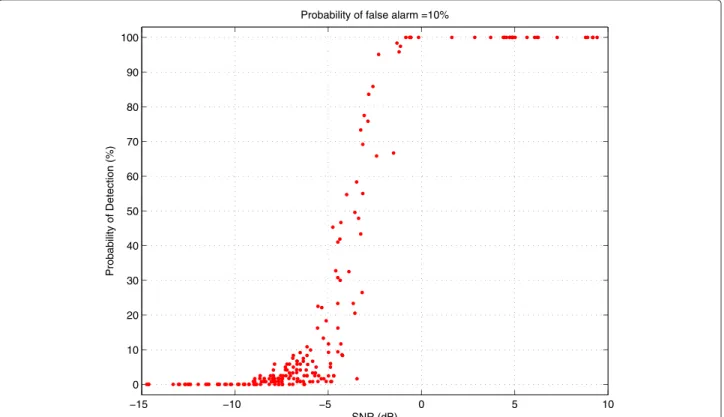
distance from generators to sensors varies between 60 and 581 m. −15 −10 −5 0 5 10 0 10 20 30 40 50 60 70 80 90 100 SNR (dB) Probability of Detection (%)
Probability of false alarm =10%
Before running the testbed as a distributed sensing net-work, we measured the sensing performance of individual nodes. Each generator sequentially broadcast an emulated WM signal with 200 kHz bandwidth at 786 MHz (DVB-T channel 60). (DVB-Transmitted power is swept from 12 dBm down to −28 dBm, decreasing the power gradually in 4 dB steps, taking 60 s for each power level. For each power iter-ation, each sensor simultaneously scans channel 60 with 1 MHz steps, during 60 s. In total, each sensor took 88 power measurements. Afterwards, the SNR for each mea-surement is estimated according to the process described in [8]. The results of the sensing campaign are presented in Figure 6, for a probability of false alarm Pfa= 10%.
Minimum requirement (Pd of 90% for Pfa = 10%)
are met when SNR > −2 dB. This is an accept-able result, taking into account the low cost and com-putational limitations of VESNA nodes, as compared with very expensive measurement equipment. More-over, this value may be further improved if we increase the sensing time or implement more advanced sensing algorithms [21].
6.2 Running the experiment
A Java application, located in the same server as the geolocation database, remotely accesses the testbed and controls it in two different modes:
1. ‘Sensing’ mode: This mode is used for coexistence studies in TVWS. Here, the network continuously scans the UHF spectrum and reports the results back to the geolocation database. A single iteration takes approximately 1 min. With similar periodicity, the WSD contacts the geolocation database and update the list of available channels.
2. ‘Sensing and generation’ mode: When using the second mode, one of the generator nodes is activated on a specific frequency, and all sensing nodes are commanded to scan the spectrum simultaneously. With this mode, the network emulates the presence of a wireless microphone in the vicinity of the
sensors, at any time. This mode is an essential tool for demonstration purposes, when wireless microphone activity is needed.
6.3 Processing experimental results
Additionally, a distributed sensing algorithm, running on the geolocation database, combines data coming from the sensor nodes (energy detection vs. position) to detect the presence of PMSE devices and provide an estimative of its location. The algorithm is based on a logical OR operation to combine information from each sensor. If one or more sensors detect an active wireless microphone, the geoloca-tion database engine computes an estimate of the wireless
microphone location through triangulation and creates an exclusion area around it; furthermore, the corresponding DVB-T channel is removed from the list of available chan-nels for that area [22], until the next sensing campaign does not detect WM activity.
7 Web-based demo
This section describes the procedure and actions to run the web-based demo [23]. The geolocation database and the LOG-a-TEC sensor network are remotely accessed using secured HTTPS connections. The demonstration flow follows:
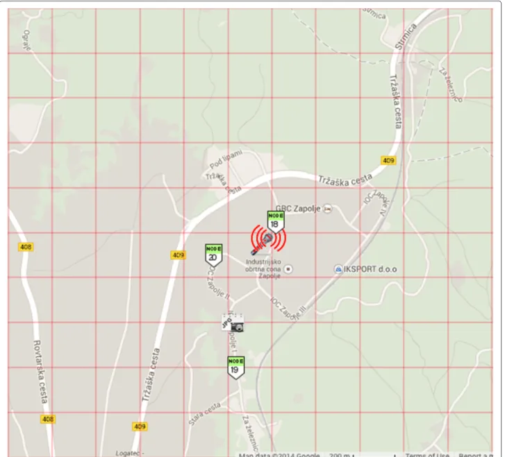
1. Remote setup Each generator nodes are previously configured to emulate a wireless microphone signal
with the characteristics described in Section 6. They are represented as wireless microphones on the web interface, as shown in Figure 7. Additionally, all seven sensor nodes are previously configured according to Section 6. These nodes appears as green flags on the web interface.
2. Generator selection The user remotely instructs one of the six generator nodes to broadcast a wireless microphone signal. For demonstration purposes, PMSE emulation was set to channel 59. The wireless microphone symbol on the GUI starts to blink. 3. Sensing process When the user starts the sensing
process from the web GUI, all sensing nodes are remotely commanded to scan the spectrum in the TV bands. DVB-T channels with TV broadcast
signals are protected by the geolocation database and therefore not sensed to detect the presence of wireless microphone signals. For demonstration purposes, the frequency range is set to the same range as the generator nodes. However, the frequency span may be programmed to the full DVB-T range (470 to 790 MHz) if the sensor
network is to be tested with real wireless microphone systems, located in the clusters area. The sensing threshold is user selectable from the web interface and was set to −93 dBm. When the sensing process is finalized, the network communicates the data to the TVWS database in RAW format for
post-processing and also to the web interface, using the Java API implemented for that purpose. As shown in Figure 8, the sensor closer to the generator detected the signal on channel 59 above threshold level (red bar). The other sensor, being further away from the generator, received a signal below threshold, and gave no indication of WM activity (blue bars).
4. Geolocation database update A distributed sensing algorithm combines the decision from each sensor node, according to a logical OR operation: If one of the sensors detects a wireless microphone, the corresponding DVB-T channel is removed from the list of available channels, for an exclusion area around the sensor that detected it. The exclusion area is computed according to the results obtained in [22]. 5. Database query A second GUI (Figure 9) allows the
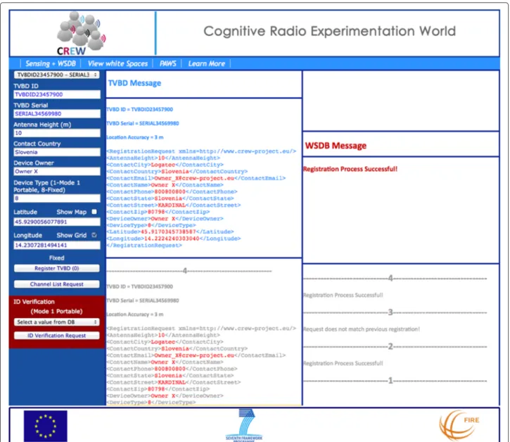
user to query the geolocation database for available TV channels, presenting the message exchange between the geolocation database and a laptop emulating a WSD. All messages are XML code that contains all relevant parameters defined from the protocol and data model requirements. This way, the user may verify that the channel removed from the sensing process is no longer present on the list of available channel where the exclusion zone was created.
8 Conclusions
In this paper, we present a successful combination of a TVWS geolocation database access with the sensing infor-mation from an outdoor infrastructured sensor network. We test the ability of the geolocation database to auto-matically create protection areas around detected PMSE devices using real-time information from the JSI sensing network.
We describe the development and implementation of a signaling protocol between master WSDs and a geolo-cation database, using a web-based environment. The protocol allows any WSD to gain access to the ser-vices of the geolocation database by communicating over
commonly used Internet protocols, using a well-defined and secure access method. The communication protocol between the LOG-a-TEC sensor network and the geolo-cation database, based on an API written in Java language, is an essential tool to implement an effective and secure connection to successfully gather sensing data and send it to the geolocation database for post-processing.
We compute TVWS availability and populate a geoloca-tion database in Slovenia. Preliminary results of the avail-able TVWS channels investigation in the Logatec area were presented, and will be used as a case study scenario in the performance evaluation of the TVWS allocation techniques in future trials.
We have also implemented two experimental method-ologies to use the testbed; one focused on coexistence studies with real wireless microphones (sensing only) and another for demonstration purposes (sensing and signal generation from the testbed). Both are valuable methods for experimenters to assess the advantages of combining sensing and geolocation database access, when protecting primary users of the UHF spectrum.
Competing interests
The authors declare that they have no competing interests.
Acknowledgements
The research leading to these results has received funding from the European Union Seventh Framework Programme FP7/2007-2013 under grant agreement no.258301 (CREW project) and grant agreement no. 318563 (CRS-i coordination action).
Received: 22 February 2014 Accepted: 14 November 2014 Published: 4 December 2014
References
1. Electronic Communications Committee - ECC, A preliminary assessment of the feasibility of fitting new/future applications/services into non-harmonized spectrum of the digital dividend. Tech. Rep. ECC24, CEPT. www.erodocdb.dk, 2008. Web. 01/04/2014
2. Electronic Communications Committee - ECC, Technical and operational requirements for the possible operation of cognitive radio systems in the ‘white spaces’ of the frequency band 470-790 MHz. Tech. Rep. ECC159, CEPT. www.erodocdb.dk, 2011. Web. 01/04/2014
3. FCC - Federal Communications Commission. www.fcc.gov, 2014. Web. 01/04/2014
4. Spectrum Bridge - Enabling Universal Spectrum Access. spectrumbridge.com, 2014. Web. 01/04/2014
5. Ofcom - Independent regulator and competition authority for the UK communications industries. stakeholders.ofcom.org.uk, 2014. Web. 01/04/2014
6. Fairspectrum. www.fairspectrum.com, 2014. Web. 01/04/2014
7. J Pak, J Um, H Jung, S Kim, B Jeong, in Proceedings of the 1st ACM Workshop on Cognitive Radio Architectures for Broadband, CRAB ’13. Advanced Cognitive Radio Test-bed with Carrier Aggregation in TV White Space (ACM, New York, NY, USA, 2013), pp. 33–40. doi:10.1145/2508478.2508483. http://doi.acm.org/10.1145/2508478.2508483. Web. 01/04/2014 8. J Ribeiro, J Ribeiro, J Rodriguez, R Dionisio, H Esteves, P Duarte, P Marques,
Testbed for combination of local sensing with geolocation database in real environments. IEEE Wireless Communications 19(4), 59 (2012). doi:10.1109/MWC.2012.6272424
9. CREW: Cognitive Radio Experimentation World. www.crew-project.eu, 2014. Web. 01/08/2014
10. PAWS - Protocol to Access WS database. datatracker.ietf.org/wg/paws/, 2014. Web. 01/08/2014
11. T Solc, C Fortuna, M Mohorcic, Low-cost testbed development and its applications in cognitive radio prototyping. chap. Cognitive Radio and Networking for Heterogeneous Wireless Networks. Springer International Publishing, pp. 361-405, 2015. doi:10.1007/978-3-319-01718-1 13 12. CEPT SE43 - White Spaces and Cognitive radio systems. cept.org, 2014.
Web. 01/08/2014
13. The European Telecommunications Standards Institute - ETSI,
Reconfigurable Radio Systems - RRS. www.etsi.org, 2014. Web. 01/08/2014 14. CogEU - Cognitive radio systems for efficient sharing of TV white spaces
in European context. www.ict-cogeu.eu, 2012. Web. 01/04/2014 15. Electronic Communications Committee - ECC, Technical and operational
requirements for the operation of white space devices under geo-location approach. Tech. Rep. ECC186, CEPT. www.erodocdb.dk, 2013. Web. 01/04/2014
16. Electronic Communications Committee - ECC, Measurements on the performance of DVB-T receivers in the presence of interference from the mobile service (especially from LTE). Tech. Rep. ECC148, CEPT. www. erodocdb.dk, 2010. Web. 01/04/2014
17. Electronic Communications Committee - ECC, Complementary Report to ECC Report 159 on further definition of technical and operational requirements for the operation of white space devices in the band 470-790 MHz. Tech. Rep. ECC185, CEPT. www.erodocdb.dk, 2013. Web. 01/04/2014
18. International Telecommunications Union, Method for point-to-area predictions for terrestrial services in the frequency range 30 MHz to 3 000 MHz. Tech. Rep. ITU R. P. 1546-4. www.itu.int, 2009. Web. 01/04/2014 19. Union International Telecommunications, Monte Carlo simulation
methodology for the use in sharing and compatibility studies between different radio services or systems, Appendix 1 to Annex 2: Propagation Model. Tech. rep. ITU-R SM.2028-1. www.itu.int, 2002. Web. 01/04/2014 20. A Bourdena, G Kormentzas, G Mastorakis, E Pallis, G Schuberth, P Marques,
J Mwangoka, J Rodriguez, F Alves, J Ribeiro, A Gomes, H Alves, C Silva, D Lavaux, Spectrum-aware routing, transport protocols and negotiation protocols between players for secondary spectrum trading; System level simulation tool - initial specification. Tech. Rep. COGEU 6.2.
www.ict-cogeu.eu, 2010. Web. 01/04/2014
21. R Dionisio, J Ribeiro, P Marques, F Alves, J Rodriguez, C Balz, M Hofmeister, J Lauterjung, Sensing algorithms for TVWS operations. Tech. Rep. COGEU 4.2, www.ict-cogeu.eu, 2011. Web. 01/04/2014
22. R Dionisio, P Marques, J Rodriguez, in IEEE International Conference on Communications - ICC2012. Interference Study between Wireless Microphone Systems and TV White Space Devices (IEEE Ottawa, Canada, June 2012), pp. 1874–1878. doi:10.1109/ICC.2012.6364101
23. J Ribeiro, R Dionisio, P Marques, CREW-TV Demo. cmsf.eu, 2014. Web. 01/08/2014
doi:10.1186/1687-1499-2014-210
Cite this article as: Dionisio et al.: Combination of a geolocation database access with infrastructure sensing in TV bands. EURASIP Journal on Wireless Communications and Networking 2014 2014:210.
Submit your manuscript to a
journal and benefi t from:
7 Convenient online submission 7 Rigorous peer review
7 Immediate publication on acceptance 7 Open access: articles freely available online 7 High visibility within the fi eld
7 Retaining the copyright to your article
![Figure 1 represents the block diagram of the demonstra- demonstra-tion platform. The rightmost side shows the diagram of the LOG-a-TEC sensor network, one of the open test plat-forms from the CREW testbed federation [9]](https://thumb-eu.123doks.com/thumbv2/123dok_br/15883166.1089521/2.892.88.810.646.1071/figure-represents-diagram-demonstra-demonstra-platform-rightmost-federation.webp)