“Try and leave the world a lit-tle better than you found it and when your turn comes to die, you can die happy in feel-ing that at any rate you have not wasted your time but have done your best.”
— Robert Smith Baden Powell
Universidade de AveiroDepartamento deElectrónica, Telecomunicações e Informática,
2009
Carlos Filipe Moreira
e Silva
Gestão Comum de Recursos Rádio em Redes Sem
Fios de Próxima Geração
Common Radio Resource Management in Wireless
Heterogeneous Networks
Universidade de AveiroDepartamento deElectrónica, Telecomunicações e Informática,
2009
Carlos Filipe Moreira
e Silva
Gestão Comum de Recursos Rádio em Redes Sem
Fios de Próxima Geração
Common Radio Resource Management in Wireless
Heterogeneous Networks
Universidade de AveiroDepartamento deElectrónica, Telecomunicações e Informática,
2009
Carlos Filipe Moreira
e Silva
Gestão Comum de Recursos Rádio em Redes Sem
Fios de Próxima Geração
Common Radio Resource Management in Wireless
Heterogeneous Networks
Dissertação apresentada à Universidade de Aveiro para cumprimento dos requisitos necessários à obtenção do grau de Mestre em Electrónica e Tele-comunicações, realizada sob a orientação científica do Professor Doutor Francisco Fontes.
Thesis submitted to the University of Aveiro for the degree of Master in Elec-tronics and Telecommunications under the supervision of Professor Fran-cisco Fontes.
o júri / the jury
presidente / president Professor Doutor Atílio Manuel Silva Gameiro
Professor Associado da Universidade de Aveiro
Vogais / Examiners committee Professor Doutor Fernando José Silva Velez
Professor Auxiliar da Universidade da Beira Interior (arguente principal)
Professor Doutor Francisco Manuel Marques Fontes
agradecimentos /
acknowledgements É com muito gosto que aproveito esta oportunidade para agradecer a to-dos os que me ajudaram durante este período de investigação e escrita desta dissertação. Quando se citam nomes acabamos sempre por esque-cer alguém, porém não posso deixar de mencionar o meu pai, José Silva, a minha mãe, Mabilda Sousa, a minha irmã, Flora Silva, o meu cunhado, Marco Miranda, o meu sobrinho e futura sobrinha, Diogo Miranda e Maria Inês Miranda. Agradeço também ao engenheiro Álvaro Gomes pela ajuda prestada na revisão técnica da dissertação.
Desejo também pedir desculpa a todos que de uma maneira ou de outra sentiram-me mais distante das tarefas mundanas. Para todos o meu muito obrigado!
I want to thank to everyone who helped me in the research and writing of this thesis. When we talk about singular names, we often forget someone, however I must mention my father, José Silva, my mother, Mabilda Sousa, my sister, Flora Silva, my brother in law, Marco Miranda, my nephew and future niece, Diogo Miranda and Maria Inês Miranda. I am also grateful to the engineer Álvaro Gomes for his technical review of the thesis.
I also want to ask for forgiveness to everyone that I do not give the impor-tance they deserve. For everyone, thanks!
palavras-chave Gestão de Recursos Rádio, Redes Heterogéneas, Redes Sem Fios, Rádio sobre Fibra Óptica
resumo A tecnologia de sinais de rádio frequência sobre fibra óptica involve o uso de links ópticos para transportar os sinais desde a unidade central de pro-cessamento até aos sites remotos (e vice-versa). A centralização do proces-samento dos sinais de rádio frequência permite a partilha de equipamentos, alocação dinâmica de recursos e uma manutenção mais simplificada do sis-tema.
Embora o conceito de gestão comum dos recursos rádio tenha despertado grande interesse na comunidade científica em termos da melhor utilização desses recursos e de novos modelos de negócio, a verdade é que a sua imple-mentação não tem sido fácil. A interligação entre diferentes componentes de rede, normalmente localizados em locais diferentes, introduz um grande atraso nas comunicações; por outro lado as implementações proprietárias e a escassez de informação global não satisfazem os requisitos de um ambi-ente extremamambi-ente dinâmico, como é o ambiambi-ente wireless. Uma topologia centralizada permite ultrapassar estas contrariedades, disponibilizando uma interligação eficiente entre as entidades locais e comuns de gestão de recur-sos rádio.
Nesta dissertação é apresentada uma nova arquitectura de gestão comum de recursos rádio, baseada no conceito de interligação entre diferentes tecnolo-gias de acesso. Esta arquitectura faz a gestão dos recursos rádio de forma centralizada, onde os sinais rádio chegam sem qualquer pré-processamento. Essa arquitectura é avaliada com a implementação de um algoritmo sim-ples de balanceamento da carga que segue a politica de minimização da interferência e aumento da capacidade.
As simulações com duas tecnologias de acesso, quando consideradas separas ou em agregado, mostraram um aumento do débito de pelo menos 51% para o mesmo valor de interferência enquanto que o erro de simbolo decresce pelo menos 20%.
keywords Common Radio Resource Management, Heterogeneous Networks, Wireless Networks, Radio over Fibre
abstract Radio over fibre technology involves the use of optical fibre links to distribute radio frequency signals from a central location to remote sites (and vice-versa). The centralisation of radio frequency signals processing functions enables equipment sharing, dynamic allocation of resources, and simplified system operation and maintenance.
Despite the unquestionable interest concept of common radio resource man-agement from the point of view of resource usage and novel business models, its implementation has not been easy. The interworking between the differ-ent local radio resource managemdiffer-ent differ-entities, usually located on differdiffer-ent places will not satisfy the requirements of the wireless dynamic behaviour due to increase of delay in communication process, less information avail-ability and proprietary implementations. A centralised topology can over-come the drawbacks of former wireless systems architecture interconnection by providing an efficient common radio communication flow with the local radio resource management entities.
In this thesis a novel common radio resource management architecture is presented based on the concept of inter-working between different technolo-gies. This is a centralised architecture where the radio frequency signals are delivered to the central location through the optical links. The new archi-tecture is evaluated with a common policy that minimises interference while the overall system capacity is increased. The policy is implemented through the load balancing algorithm.
The simulations of two radio access technologies when separately and jointly considered show that when the load balancing algorithm is applied the avail-able throughput increases in at least 51% while the symbol error rate de-creases at least 20%.
Contents
1. Introduction 27 1.1. Objectives 29 1.2. Contributions 29 1.3. Assumptions 29 1.4. Thesis Organisation 302. Local and Common RRM 31
2.1. Overview of LRRM Techniques 32
2.1.1. Wireless Fidelity (WiFi) 32
2.1.2. Universal Mobile Telecommunications System (UMTS) 34 2.1.3. Worldwide Interoperability for Microwave Access (WiMAX) 37
2.1.4. Long Term Evolution (LTE) 38
2.2. Overview of CRRM Techniques 40 2.2.1. CRRM Main Functionalities 41 2.2.2. 3GPP CRRM Functional Model 41 3. Novel CRRM Architecture 47 3.1. Architecture Description 47 3.2. Design Principles of CRRM 51
3.2.1. Functionalities of LRRM and CRRM Entities 51
3.2.2. CRRM based on Vertical Handover 52
3.2.3. Admission Control 54
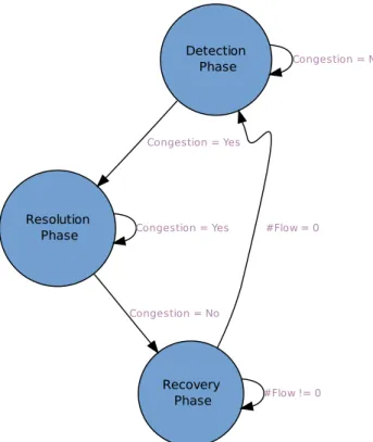
3.2.4. Congestion Control 56
3.3. Measurements and Statistical Information 58
3.4. Summary of Adopted Schemes 59
4. Radio Interference Scenarios 61
4.1. Interference in Wireless and Cellular Networks 61
4.2. Interference in WCDMA Systems 62
4.2.1. System Capacity 63
4.2.2. Intra-cell Interference 66
4.2.3. Inter-cell Interference 67
XVI OF105 CONTENTS
4.3. Interference in OFDMA Systems 69
4.3.1. Intra-cell Interference 70
4.3.2. Inter-cell Interference 70
4.3.3. System Capacity 71
4.4. WCDMA and OFDMA Interference Summary 73
5. CRRM Policies and Algorithms 75
5.1. Load Balancing Algorithm for Technology Selection 75
5.1.1. Vertical Handover 76
5.1.2. Admission Control 77
5.1.3. Congestion Control 81
5.2. Policies Evaluation 82
5.2.1. Simulation Scenario Description 82
5.2.2. Achieved Results 83
5.2.3. Discussion of Results 88
6. Conclusion 91
6.1. Future Work 92
A. Radio Propagation Model 101
A.1. Free Path Loss Formulation 101
List of Figures
2.1. UMTS radio interface: RRM blocks divided per L2 and L3 32
2.2. 3GPP CRRM functional model 43
3.1. Novel CRRM architecture 48
3.2. LRRM placement in CU versus legacy system (UTRAN) 50
3.3. RRM functionalities divided per entity 52
3.4. VHO/AC in distributed and centralised fashion 53
3.5. AC and uplink interference in UMTS 56
3.6. Congestion control phases 58
4.1. OFDMA sub-carriers 69
5.1. Possible VHO process 77
5.2. AC process based on LB algorithm for RAT1 and RAT2 79
5.3. WiMAX frame structure 81
5.4. The simulation scenario 82
5.5. Available throughput and SER for uniform distributed users in RAT1 without
algorithm 84
5.6. Available throughput and SER for uniform distributed users in RAT2 without
algorithm 85
5.7. Aggregated available throughput and SER for uniform distributed users in
RAT1+RAT2 with CRRM LB algorithm 86
5.8. Average available throughput for different positions in the cell 87
5.9. Average SER for different positions in the cell 87
List of Tables
2.1. Interaction degrees between LRRM and CRRM entities 44 3.1. Measurements and statistical information required by CRRM 59
3.2. Adopted schemes for CRRM algorithms 59
4.1. Minimum values of adjacent-channel leakage ratio, selectivity and protection
for the first adjacent-channel 67
4.2. Receiver SNR assumptions 71
5.1. Simulation parameters 83
5.2. Aggregated gains in percentage when the CRRM LB algorithm is applied to
RAT1+RAT2 88
List of Acronyms and Abbreviations
3G Third Generation3GPP 3rdGeneration Partnership Project
AAA Authentication, Authorization and Accounting ABC Always Best Connected
AC Admission Control
AP Access Point
AWGN Additive White Gaussian Noise B3G Beyond Third Generation BER Bit Error Rate
BLER Block Error Rate
BPSK Binary Phase Shift Keying
BS Base Station
BSC Base Station Controller CAC Call Admission Control CC Congestion Control
CDMA Code Division Multiple Access C/I Carrier-to-Interference
CMC Connection Mobility Control
COST COperation européenne dans le domaine de la recherche Scientifique et Technique
CPCH Common Physical Channel
CRRM Common Radio Resource Management
XXII OF105 LIST OFACRONYMS ANDABBREVIATIONS
CU Central Unit
CWmin Minimum Contention Window DPCH Dedicated Physical Channel DRA Dynamic Resource Allocation
eNB Evolved Universal Mobile Telecommunications System Terrestrial Radio Access Network Node B
E-UTRAN Evolved Universal Mobile Telecommunications System Terrestrial Radio Access Network
FACH Forward Access Channel FDD Frequency Division Duplex
FDMA Frequency Division Multiple Access FUSC Full Usage Sub-Channels
FUTON Fibre Optic Networks for Distributed, Extendible Heterogeneous Radio Architectures and Service Provisioning
GERAN Global System for Mobile Communications/Edge Radio Access Network GPRS General Packet Radio Service
GSM Global System for Mobile Communications HCS Hierarchical Cell Structure
HHO Horizontal Handover HoF Handover Function
ICIC Inter-Cell Interference Coordination
IEEE Institute of Electrical and Electronics Engineers IFFT Inverse Fast Fourier Transform
IP Internet Protocol
ISI Inter-Symbol Interference
LB Load Balancing
LC Load Control
LRRM Local Radio Resource Management LS Link Selection
XXIII OF105
MAC Media Access Control MDB Middleware Database MIHO Mobile Initiated Handover MIMO Multiple Input Multiple Output MME Mobility Management Entity MRRC Maximal-Ratio Receiver Combining
MT Mobile Terminal
NB Node B
NIHO Network Initiated Handover NRT Non-Real Time
ns2 Network Simulator 2
OFDM Orthogonal Frequency Division Multiplexing OFDMA Orthogonal Frequency Division Multiple Access OVSF Orthogonal Variable Spreading Factor
PC Power Control
PDCP Packet Data Convergence Protocol PER Packet Error Rate
PHY Physical Layer Device PS Packet Scheduling
QAM Quadrature Amplitude Modulation QoE Quality of Experience
QoS Quality of Service
QPSK Quadrature Phase Shift Keying RAB Radio Access Bearer
RAC Radio Admission Control RAN Radio Access Network RAT Radio Access Technology RAU Remote Access Unit RBC Radio Bearer Control
XXIV OF105 LIST OFACRONYMS ANDABBREVIATIONS
RF Radio Frequency
RLC Radio Link Control RNC Radio Network Controller RoF Radio over Fibre
RRC Radio Resource Control RRM Radio Resource Management RRU Radio Resource Unit
RT Real Time
SCM Service Connection Manager SER Symbol Error Rate
SF Service Flow
SFID Service Flow Identifier
SINR Signal-to-Interference and Noise Ratio SIR Signal-to-Interference Ratio
SLA Service Level Agreement SNR Signal-to-Noise Ratio SPID Subscriber Profile Identifier SUI Stanford University Interim TCP Transmission Control Protocol TDD Time Division Duplex
TDMA Time Division Multiple Access TxOP Transmit Opportunity
UMTS Universal Mobile Telecommunications System UPE User Plane Entity
UTRAN Universal Mobile Telecommunications System Terrestrial Radio Access Network VHO Vertical Handover
VoIP Voice over IP
WCDMA Wideband Code Division Multiple Access WiFi Wireless Fidelity
XXV OF105
WiMAX Worldwide Interoperability for Microwave Access WLAN Wireless Local Area Network
CHAPTER 1
Introduction
O
NE of the main trends in the mobile communications sector is the possibility to be connected anywhere, anytime, anyhow philosophy. This is the Always Best Connected (ABC) philosophy. It is based on the fact that several competing technologies, which have different requirements and capabilities can co-exist. This approach tries to select always the best network according to a set of requirements and perform the inter-system handover between them, when those requirements are not fulfilled.Wireless communication systems are dynamic by nature. Dynamism comes from several factors: radio propagation impairments, traffic changes, interference conditions, or user mobility. Thus, the dynamic network behaviour demands for a dynamic radio resources management, which is carried out by the Radio Resource Management (RRM) mechanisms. This mechanism has associated a large number of parameters and quality/performance indicators that need to be set, measured, analysed and optimised.
Radio over Fibre (RoF) technology involves the use of optical fibre links to distribute Radio Frequency (RF) signals from a central location to Remote Access Units (RAUs) (and vice-versa). The centralisation of signals processing functions enables equipment sharing, dy-namic allocation of resources, and simplified system operation and maintenance. Since switching, modulation, and other RF functions are performed at a central location, dy-namic radio resource configuration and capacity allocation is feasible. In this context, Base Stations (BSs) are significantly simplified as they only need to perform optical-electronic con-version and amplification functions. Consequently, they may be more compact, cost-effective and easier to deploy. These bring major benefits in system installation and operational sav-ings, especially in wide-coverage broadband wireless communication systems, with a high density of BSs. Therefore, in order to increase the radio capacity and minimise the interfer-ence, novel RRM algorithms and mechanisms shall be addressed, taking advantage of RoF centralised topology and increased number of RAUs that can be deployed.
Each RAU simply consists of basic RF converters, radiating elements or antennas, and electro-optical conversion modules, which greatly reduces the complexity of the cell-sites by
28OF105 1. INTRODUCTION
concentrating all the signal processing capabilities in the Central Unit (CU). This characteris-tic allows the potential improvement/optimisation of existing and the deployment of novel joint processing, cross-layer and cross-system algorithms for distributed and heterogeneous wireless systems.
The scenario of an heterogeneous wireless environment with multi-mode terminals, where several Radio Access Technologies (RATs) coexist, introduces a new dimension into the RRM problem. Instead of performing the management of the radio resources independently for each RAT, an overall and global management of the pool of radio resources can be envisaged. The Common Radio Resource Management (CRRM) is the process envisaged to manage dynamically the allocation and de-allocation of radio resources within a single or between different radio access systems for the fixed spectrum bands allocated to each of these systems, achieving a more efficient usage of the available radio resources.
Up to now the CRRM concept, despite its unquestionable interest from the point of view of resource usage and novel business models, has not been easy to implement. The interwork-ing between different Local Radio Resource Management (LRRM) entities, usually located on different places, which may greatly increase the delay and the message exchange overload, will not satisfy the requirements of wireless dynamic behaviour. Furthermore, the different implementations and proprietary software limit the communication process that do allow an efficient common management in the heterogeneous scenario. A centralised topology can overcome the drawbacks of former wireless systems architecture interconnection by providing an efficient CRRM communication flow with the LRRM entities.
Depending on the implementation, the CRRM may contain several functionalities such as: initial RAT selection, joint Admission Control (AC), joint Congestion Control (CC), cell selection and Vertical Handover (VHO) algorithms. Considering this top and integrated view of the available radio resources, an higher efficiency on its usage can be achieved, guaranteeing the planed coverage, the contracted Quality of Service (QoS) for each service and the planed blocking rate by limiting the user interference within the same cell or inter-cell interference
Due to the high capacity of optical fibre infrastructure, the main application was initially done at core backbone networks. In contrast, wireless networks were greatly affected by the propagation environments, thus they were mainly dedicated to low and medium data rate mobility scenarios. However, the dramatic drop in the cost of optical fibre networks and the advent of powerful signal processing capabilities for wireless communications have led to a natural convergence between these two previously independent technologies. Low cost optical fibre networks means that they can be extended with no problems almost to the end user, e.g., in fibre to the home applications. On the other hand, wireless technologies have created in the user a sense of freedom and mobility which together with the proliferation of advanced user terminals and processing algorithms have contributed to an explosive demand for faster and better wireless connections. Therefore, it seems natural to think about high speed wireless access radio technology combined with optical fibre networks in order to achieve the stringent requirements of next generation networks.
1.1. OBJECTIVES 29OF105
The propose of FUTON [18] project is the development of a hybrid fibre-radio infrastructure transparently connecting the RAUs to a CU where the joint processing is performed. This concept allows the development of virtual multiple transmission/reception antennas to achieve broadband wireless transmission and inter-cell interference cancellation. Further-more, the fact that the management of several heterogeneous systems is co-localised enables the development of efficient procedures for a joint management of the radio resources.
1.1. Objectives
The objectives of this thesis may be summarised as:1. Characterise the state-of-art about mechanisms of RRM and CRRM in heterogeneous wireless systems;
2. Study of the main problems in wireless networks regarding radio resources, namely interference, which limits coverage and the total admitted users1. The CRRM policy under study may be enunciate as: minimise interference and increase the overall system capacity (and, if possible, also coverage);
3. Propose a new architecture for CRRM which takes advantage of centralised infor-mation availability and joint processing while being compatible with 3rdGeneration
Partnership Project (3GPP) standards;
4. Implement an algorithm for the proposed CRRM policy, which is the Load Balancing (LB) algorithm;
5. Validate the CRRM architecture, evaluating the behaviour of the implemented algo-rithm for the studied CRRM policy that is proposed within the context of the new architecture.
1.2. Contributions
The main contributes for this thesis were achieved during the participation of the author in the European project FUTON. Namely in Work Package 4 (WP4) [19, 20].
1.3. Assumptions
The author assumes an heterogeneous wireless environment characterised as follows:
30OF105 1. INTRODUCTION
• Different wireless technologies share the same geographical area, namely Universal Mobile Telecommunications System (UMTS) and Worldwide Interoperability for Mi-crowave Access (WiMAX);
• Considering different Radio Access Networks (RANs), multiple cells with different radio access modes and operating on different frequencies may overlap and multiple cell layers (macro, micro, pico) will co-exist. This situation must be met otherwise the inter-system handover cannot be performed;
• It is assumed that every RAN already have their own LRRM entities for performance optimisation and radio management inside the RAN;
• The physical parameters and measurements can be obtained from terminals and somehow from the legacy (proprietary) networks;
• The terminals are multi-mode terminals, thus they can connect to different RATs.
1.4. Thesis Organisation
The thesis is organised in the following way:Chapter 2: the state-of-art regarding RRM in different wireless and cellular networks is presented. In the end of this section it is presented the vision of 3GPP about CRRM, which is the followed approach in the thesis.
Chapter 3: the novel CRRM architecture is presented and described. The adopted principles regarding the design of CRRM solutions for the architecture are also stated in the section.
Chapter 4: in this chapter the author studies the interference problems inside multi-user technologies when it it necessary to access to the RF spectrum, namely Wideband Code Division Multiple Access (WCDMA) (which is the RAT used in UMTS) and Orthogonal Frequency Division Multiple Access (OFDMA) (which is the RAT used in WiMAX), both for downlink and uplink.
Chapter 5: the new architecture is evaluated in terms of CRRM for a particular scenario where two technologies, RAT1 and RAT2, are co-localised. The cell in the centre is the one under study, while the outer cells are interfering ones. The policy and the algorithm are implemented in a simulator. Finally, the discussion of results is done. The thesis ends with the conclusions and possible future work.
CHAPTER 2
Local and Common RRM
T
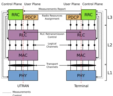
HERRM is a system level control of co-channel interference and other radio transmission characteristics in wireless communication systems, either cellular networks, wireless networks or broadcasting systems. RRM involves strategies and algorithms for controlling pa-rameters such as transmit power, channel allocation, handover criteria, modulation scheme, and error coding scheme. The objective is to utilise the limited RF spectrum resources and radio network infrastructure as efficiently as possible. Furthermore, RRM concerns to multi-user and multi-cell network capacity issues, rather than point-to-point channel capacity.In the protocol stack, RRM functions can be divided between the link (L2) and network (L3) layers, considering the information requirements, the target object and functions that are available. In figure 2.1 the example of UMTS radio interface is represented. The Radio Re-source Control (RRC) entirely belongs to the control plane, hence it has no data information, only control information. It receives measurements from Media Access Control (MAC) and Physical Layer Device (PHY) layers and sends control information to Radio Link Control (RLC), MAC and PHY layers.
RRM may be static or dynamic: dynamic RRM schemes are considered in the design of wireless systems, in view to minimise expensive manual cell planning and achieve tighter frequency reuse patterns, resulting in improved system spectral efficiency. Dynamic RRM schemes adaptively adjust the radio network parameters to the traffic load, user positions, or QoS requirements. Some schemes are centralised, where several BSs and Access Points (APs) are controlled by a Radio Network Controller (RNC); others are distributed, either autonomous algorithms in terminals, BSs or wireless APs, or coordinated by exchanging information among these stations.
In [1] 3GPP introduced the concept of CRRM, which is further enhanced in [2]. That docu-ment starts like this: In the future, the mobile network configurations will not be as simple as
in nowadays. Multiple cells from different radio technologies will be overlapped in the same area and multiple layers will co-exist. In this complicated environment, multi-mode mobile
32OF105 2. LOCAL ANDCOMMONRRM RLC MAC PHY RRC PDCP RLC MAC PHY RRC PDCP
Control Plane User Plane User Plane Control Plane
Logical Channels Measurements Report Radio Resources Assignment RLC Retransmission Control UTRAN Terminal Transport Channels Measurements Control L3 L2 L1
Figure 2.1.: UMTS radio interface: RRM blocks divided per L2 and L3
can be connected to different cell and unless there is knowledge about each cell it would be very difficult to optimise network performance and to manage resources efficiently. In addition, it would be reasonable to direct different services with different QoS classes to the most suitable radio accesses.
Further, 3GPP defines LRRM and CRRM entities and suggests three different topologies: CRRM integrated into every RNC/BSC, CRRM integrated only in some RNC/BSCs, and CRRM as a stand-alone server. The last option is the one that is explored in this thesis.
2.1. Overview of LRRM Techniques
In this section is provided an overview regarding the RRM techniques considered for legacy and new systems. Many of them are common to many technologies, while others are technology-specific.
2.1.1. Wireless Fidelity (WiFi)
Wireless Fidelity (WiFi), also known as IEEE 802.11 standard, does not originally include RRM techniques. However, the RRM techniques were required for industrial environments and offices, thus new standards had to be developed. The first was IEEE 802.11h, which has already been integrated into the full IEEE 802.11-2007 standard [26], and the newer IEEE 802.11k.
2.1. OVERVIEW OFLRRM TECHNIQUES 33OF105
The working groups proposed three RRM techniques: dynamic channel assignment, dynamic transmit Power Control (PC), and load sharing [21].
Dynamic Channel Assignment
The performance of a network depends, in part, on the assignment of radio channels to each AP. The optimal channel assignment for a given Wireless Local Area Network (WLAN) should minimise the overlap between coverage areas of co-channel APs. This will enhance the performance of the network by reducing interference between co-channel APs.
The coverage areas, and therefore the channel assignments, are dependent on, among other things, the radio propagation environment; the radio propagation environment changes, which make impossible to be sure that the channel assignments valid at the time that network was designed will continue to be valid. With RRM techniques it is possible to dynamically adjust channel assignments accordingly.
There are 14 radio channels available at 2.4GHz to use in IEEE 802.11b/g worldwide.
Dynamic Transmit Power Control
The dynamic transmit PC has the potential to reduce the effort involved in the site survey and design of a WLAN. It may be possible to carry out an abbreviated site survey and design process, placing APs in good, if not the best, locations (which provides a complete coverage without excessive coverage overlap) and allowing the dynamic transmit PC capability to make the necessary adjustments.
Furthermore, to facilitate the dynamic channel assignment, the dynamic transmit PC ac-commodates the changes in the propagation environment, and also compensates the lost coverage due to failed APs.
It can be used the inter-AP received signal strengths as a proxy for coverage overlap. The APs listen to each others signals, and the transmit power of each AP is set in a way that will achieve the desired signal strength at (and coverage overlaps with) other APs.
Until the year 2004, the transmit PC technique only affected the transmit power of APs (the downlink coverage area). The IEEE 802.11 standard does not provide a way for the WLAN infrastructure (e.g., an intelligent switch/AP combination) to control the transmit power of clients and, therefore, uplink coverage area.
Load Sharing
An AP and its associated clients share a limited bandwidth resource. This limitation implies that APs may become overloaded, which conducts to performance degradation.
34OF105 2. LOCAL ANDCOMMONRRM
However, since clients may be able to communicate quite successfully with two or more APs, redistributing associations among APs more or less uniformly so that no AP becomes overloaded may considerably enhance the network performance. Thus, if an AP is heavily loaded, it might not be the best candidate to accept a new association request. If such request is received and the RRM is running on the intelligent switch, which knows that a lightly loaded AP is also within radio range of the requesting client, it may decide that it is better for the requested AP to deny the association (and the association would be done with the lightly loaded AP).
2.1.2. Universal Mobile Telecommunications System (UMTS)
The RRM modules for UMTS are: AC, CC/LC, handover control, PC, and Packet Scheduling (PS) control. The functions for each of these modules are presented bellow.
Admission Control
AC handles all new incoming traffic checking whether new connections can be admitted to the system and generates parameters for them. It occurs when new connection is set up as well during handovers and bearer modification.
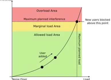
If the load of air interface increases excessively, the coverage area of the cell is reduced below the planned values, which is known as cell breathing (and QoS cannot be guaranteed). The breathing phenomenon occurs because Code Division Multiple Access (CDMA) technologies are an interference-limited system.
Admitting a new call always increases the cell load. In order to avoid overload situations, the AC will limit the increase of this load. The principle is to check the current load in the system plus the expected resource consumption of the new call against the AC threshold. The load estimation is applied both for downlink and uplink. The requesting bearer can be admitted only if the admission is made in both directions, otherwise it is rejected because of the excessive interference that it adds to the network. Although, as the AC techniques are applied separately for downlink and uplink, different AC strategies may be used in each direction.
In case the admission check fails, the basic strategy is to protect ongoing calls by denying the new user access to the system, since dropping is assumed to be more annoying than blocking.
Generally, the AC strategies can be divided into two types: power- and throughput-based AC strategy. In the first strategy, new users are not admitted if the new resulting interference level is above of the maximum uplink noise rise (near-far problem). In the second strategy, users are not admitted if the new resulting total load is higher than the threshold throughput value.
2.1. OVERVIEW OFLRRM TECHNIQUES 35OF105
Congestion Control and Load Control
One important task of the RRM functionalities is to ensure that the system is not overloaded and remains stable. Furthermore, if the system is properly planned, and the AC works well, overload situations are exceptional.
However, due to mobility (especially of high data rate users) overload situations occur even if an efficient AC algorithm is used. When overload is encountered the CC (also known as Load Control (LC)) returns the system quickly and controllably back to the targeted load, which is defined in the radio network planning phase.
Some possible actions that can be used by the CC in order to reduce or balance load are: • Decrease data rate of one or several services that are insensitive to delay;
• Inter-frequency or inter-system handover; • Drop calls in a controlled way.
Handover Control
Handover is an essential component of mobile cellular communication systems. Mobility causes dynamic variations in link quality and interference levels, which sometimes require that a particular user changes its serving Node B (NB)1.
The objectives of handover can be summarised as follows [13]:
• Guarantee the continuity of wireless services when the mobile user moves across the cellular boundaries;
• Keep the required QoS;
• Minimise the interference level of the whole system by keeping the mobile linked to the strongest NB;
• Roaming between different networks; • LB.
Different types of handovers may be considered in UMTS:
• Soft/Softer handover (dedicated channels with the same carrier);
• Hard handover (shared channels or dedicated channels with different carriers); • Inter-frequency handover;
• Inter-system handover (e.g., UMTS/GSM); • Cell selection/reselection (inactive or idle).
36OF105 2. LOCAL ANDCOMMONRRM
Power Control
PC is a necessary element in all mobile systems because of the battery life problem and safety reasons. In WCDMA systems, PC is essential because it optimises the system capacity by controlling interference and overcomes the near-far effect in the uplink.
For WCDMA systems and in the same direction (downlink or uplink), all users share the same channel (same carrier). Two terminals have different codes (Code Division Multiple Access) attributed by NB. In this sense, if one terminal increases its transmit power to reach the NB without being controlled, it will probably block other terminals that have lower transmit power.
The near-far problem in the uplink direction is well known in literature [38]. Signals from different terminals are transmitted in the same frequency band simultaneously and the spreading codes are not perfectly orthogonal. Without PC the signal coming from the nearest terminal to the NB may block signals from other terminal that are farer away from the NB; or farer way terminals would increase the transmit power, which would highly increase the noise of the system.
In downlink direction there is no near-far problem due to the one-to-many scenario. In this direction, PC is responsible for compensating the inter-cell interference suffered by terminals, especially those who are near the cell boundaries. Moreover, PC in the downlink is responsible for minimising the total interference by keeping the QoS at its target value. There are mainly three types of PC algorithms in WCDMA systems:
Open loop PC: this relates directly to the path loss. As the name suggests, this control has no feedback. Thus, it simply sets the initial power at which the terminal should transmit. This initial setting happens via RRC signalling. The open loop PC is done in the terminal and RNC.
Outer loop PC: this relates to long term variations of the channel. A target Signal-to-Interference Ratio (SIR) is specified and if the received SIR is less than this target, the transmit power needs to be increased, otherwise it needs to be decreased. In practice, downlink target quality is in terms of transport channel Block Error Rate (BLER). BLER can be related to a target SIR. If the received SIR is less than the target then BLER is likely to be not met. Alternatively, if the BLER is more than the target, the transmit power has to be increased. This control is in the terminal and the RNC. This is also known as slow closed loop PC, because it happens at the rate of 10 − 100Hz.
Inner loop PC: this is also known as fast closed loop PC. It happens at a rate of 1500Hz to combat fast fading and is done in the terminal and the NB. While outer loop control is set at RRC level and executed at L2, fast PC happens at L1 in order to meet the BLER target set by outer loop control. The effect of this control is that even in a fading channel, the received power is maintained constant so as to achieve the target BLER.
2.1. OVERVIEW OFLRRM TECHNIQUES 37OF105
Packet Scheduling Control
The PS control monitors the system load and controls the existing data session scheduling in an efficient way.
It handles all Non-Real Time (NRT) traffic, deciding when a packet transmission is initiated and its bit rate. Moreover, PS control is also responsible to initiate the transport channel type, switching between common, shared and dedicated channels when necessary.
2.1.3. Worldwide Interoperability for Microwave Access (WiMAX)
The standards of the IEEE 802.16 family provide fixed and mobile broadband wireless access and promise to deliver high data rate services over large areas, based on complexity and flexibility management of the MAC and PHY layers. The IEEE 802.16 family is expected to improve the delivered QoS, namely when compared with UMTS [23].
Although IEEE 802.16 specifications define the signalling messages for the multiple access mechanisms and WiMAX Forum2streamlines the implementation of IEEE 802.16 standards, namely Mobile WiMAX also known as IEEE 802.16e, the RRM protocols and many aspects of network control and management are left unspecified on purpose for innovations by individual equipment vendors as a way to differentiate their products in the marketplace. In Mobile WiMAX RRM algorithms include: Call Admission Control (CAC), adaptive trans-mission, and Horizontal Handover (HHO).
Call Admission Control
The CAC algorithm handles system overloading and satisfies the QoS by limiting the number of users in the system (i.e., deciding if new user shall be or not admitted to the network). The goals of CAC are related with satisfying the QoS requirements for admitted users, maximising the network capacity, and support fairness and priorities among users [7, 31].
The CAC schemes are based on Signal-to-Interference and Noise Ratio (SINR), interference, bandwidth, load, or system capacity [7, 31]. However, in [29, 32] the admission of new users is based on the analysis of the current status of active users queues.
In Mobile WiMAX network the most suitable scheme is the one that maximises network capacity, while satisfying QoS for all admitted users [16].
Adaptive Transmission
The adaptive transmission enables the adaptation of PHY layer parameters to the changes in the reception conditions.
38OF105 2. LOCAL ANDCOMMONRRM
The adaptive transmission includes scheduling, adaptive modulation and coding, PC, and time-frequency resource allocation. In OFDMA with the multi-user diversity, adaptive re-sources allocation algorithms play an important role. The receiving conditions are dependent on sub-channels frequency, thus users can be assigned to sub-channels with the best receiv-ing conditions, achievreceiv-ing multi-user diversity gain. These algorithms when performed in OFDMA networks are computational complex due to large degrees of freedom, and most of them do not perform a joint downlink and uplink optimisation.
For example, in the case of frequency diversity, the adaptation parameters are position of the frame boundary between the downlink and uplink subframes, coding and modulation schemes, and transmission power values of downlink and uplink Service Flows (SFs). Posi-tions of service flows within the downlink and uplink subframes may be selected arbitrary. However, the optimisation for these service flows on the frame-by-frame basis shall be considered to achieve the desired QoS.
Horizontal Handover
HHO guarantees the continuous service by assigning a new serving BS to user in the cellular environment when the receiving conditions degrade. The receiving conditions are charac-terised by the signal level or SINR. Although, to guarantee the QoS requirements, not only the downlink and uplink receiving conditions shall be taken into account but also the load of the serving sector. New algorithms are an enhancement to the traditional algorithms, which only consider the signal level or SINR and not the load of sector, thus cannot guarantee the QoS requirements.
2.1.4. Long Term Evolution (LTE)
The text in this section is based on the last studies done in the scope of RRM functions for Long Term Evolution (LTE) technology [3, section 16.1], proposed by 3GPP, which is presented here as a reference in Beyond Third Generation (B3G) systems.
For LTE the set of RRM functionalities include: Radio Bearer Control (RBC), Radio Admission Control (RAC), Connection Mobility Control (CMC), Dynamic Resource Allocation (DRA) or PS, Inter-Cell Interference Coordination (ICIC), LB, inter-RAT RRM, and Subscriber Profile Identifier (SPID) for RAT/frequency priority.
Radio Bearer Control
The establishment, maintenance and release of radio bearers involve the configuration of radio resources associated with them. When setting up a radio bearer for a service, RBC takes into account the overall situation of resources in E-UTRAN, the QoS requirements of in-progress sessions and the QoS requirement for the new service. RBC is also concerned with the maintenance of radio bearers of in-progress sessions at the situation change of the radio
2.1. OVERVIEW OFLRRM TECHNIQUES 39OF105
resources due to mobility or other reasons. RBC is involved in the release of radio resources associated with radio bearers at session termination, handover or at other occasions.
Radio Admission Control
The task of RAC is to admit or reject the establishment requests for new radio bearers. In order to do this, RAC takes into account the overall resource situation in E-UTRAN, the QoS requirements, the priority levels and the provided QoS of in-progress sessions, and the QoS requirement for the new radio bearer request. The goal of RAC is to ensure high radio resource utilisation by accepting radio bearer requests as long as radio resources are available and at the same time to ensure proper QoS for in-progress sessions by rejecting radio bearer requests when they cannot be accommodated.
Connection Mobility Control
CMC is concerned with the management of radio resources in connection with idle or connected mode mobility. In idle mode, the cell reselection algorithms are controlled by the setting of parameters (thresholds and hysteresis values) that define the best cell and/or determine when the terminal should select a new cell. E-UTRAN also broadcasts parameters that configure the measurement and reporting procedures. In connected mode, the mobility of radio connections has to be supported. Handover decisions may be based on terminal and eNB3measurements. In addition, handover decisions may take other inputs, such as neighbour cell load, traffic distribution, transport resources and policies.
Dynamic Resource Allocation or Packet Scheduling
The task of DRA or PS is to allocate and de-allocate resources (including buffer, processing resources and chunks (resource blocks)) to user and control plane packets. DRA involves several sub-tasks, including the selection of radio bearers whose packets have to be scheduled and managing the necessary resources (e.g., the power levels or the specific used resource blocks). DRA typically takes into account the QoS requirements associated with the radio bearers, the channel quality information for terminals, buffer status, or interference situation. DRA may also take into account restrictions or preferences on some of the available resource blocks or resource block sets due to ICIC considerations.
Inter-Cell Interference Coordination
ICIC has the task to manage radio resources (notably the radio resource blocks) such that inter-cell interference is kept under control. ICIC is inherently a multi-cell RRM function that needs to take into account information (e.g., the resource usage status and traffic load
40OF105 2. LOCAL ANDCOMMONRRM
situation) from multiple cells. The preferred ICIC method may be different for downlink and uplink.
Load Balancing
LB has the task to handle uneven distribution of the traffic load over multiple cells. The purpose of LB is thus to influence the load distribution in such a manner that radio resources remain highly utilised and the QoS of in-progress sessions are maintained to the extent possible and call dropping probabilities are kept sufficiently small. LB algorithms may result in handover or cell reselection decisions with the purpose of redistribute traffic from highly loaded cells to underutilised ones.
Inter-Radio Access Technology Radio Resource Management
Inter-RAT RRM is primarily concerned with the management of radio resources in connection with inter-RAT mobility, notably inter-RAT handover. At inter-RAT handover, the handover decision may take into account the resources of involved RATs as well as the terminal capa-bilities and operator policies. The importance of inter-RAT RRM may depend on the specific scenario in which E-UTRAN is deployed. Inter-RAT RRM may also include functionalities for inter-RAT LB for idle and connected mode terminals.
Subscriber Profile Identifier for Radio Access Technology/Frequency Priority The RRM strategy in E-UTRAN may be based on user’s and usage specific information. The SPID parameter received by the eNB via the s1 interface4is an index referring to user information (e.g., mobility profile, service usage profile and roaming restrictions). The information is specific to the terminal and applies to all its radio bearers.
This index is mapped by the eNB to a locally defined configuration in order to apply specific RRM strategies.
2.2. Overview of CRRM Techniques
In legacy cellular networks, each network is seen as a tight system and does not interact with other systems. Here the available Radio Resource Units (RRUs) are locally managed by the logical entity LRRM (e.g., the NB and RNC in UMTS).
In a B3G scenario, where several RATs co-exist, the management of the provisioned RRUs can be seen as a problem with different dimensions. Every RAT is based on a specific multiple
2.2. OVERVIEW OFCRRM TECHNIQUES 41OF105
access mechanism, which exploits different orthogonal dimensions, such as frequency, time and code.
This heterogeneous scenario must also be seen as a new challenge in order to deliver services to users over an efficient and ubiquitous radio access thanks to coordination (joint processing information) of the available RATs. Thus, user may not only be served through the RAT that fits better to the terminal capabilities and service requirements, but also a more efficient use of the available radio resources can be achieved [17].
This overview will mainly focus on the 3GPP CRRM functional model which is the starting point for the new CRRM architecture proposal.
2.2.1. CRRM Main Functionalities
As shown in section 2.1, within the context of a single technology the RRM functions are more or less related with AC, CC, handover control, PC, and PS. In an heterogeneous environment, these functions can be donated as common (common AC, common PC, etc.).
In this scenario, the main CRRM function is related with collecting information from different LRRM entities (one per cell) and make decisions, namely the RAT selection, of the RAT that better fits according to policies.
When the terminal is switched on, an initial RAT selection is performed based on the available technologies and user’s or usage profile. Then when a new request for a session exists and if there are not enough resources in that RAT the migration of the terminal connection to another serving RAT is the next step. However, if there is already an ongoing session, this migration process is called VHO and shall be seamless and fast enough.
The VHO provides mechanisms to rearrange traffic in a certain area, thus it may be useful for many reasons. Next some of those reasons are presented:
• LB;
• Services based on RAT; • QoS improvements;
• Lack of coverage of current RAN; • Avoid blocking users.
2.2.2. 3GPP CRRM Functional Model
The functional model assumed in 3GPP for CRRM operation [1, 2] considers the whole set of radio resources to be divided into radio resource pools.
Each radio resource pool consists in a set of resource units available in a set of cells, under the control of, e.g., a RNC in UTRAN or Base Station Controller (BSC) in GERAN.
42OF105 2. LOCAL ANDCOMMONRRM
Although, the 3GPP CRRM mechanisms are proposed to be mainly used in UMTS and Global System for Mobile Communications (GSM), the next description tries to extend the 3GPP concepts and apply them to any heterogeneous wireless scenario. For example, instead of referring the interface names (cc-i/f which connects CRRM entities and rc-i/f which connects CRRM and LRRM entities [2]), they will be referred generally as interfaces and the description will be focus their capabilities/functionalities.
Two types of logical entities are considered for the management of these radio resource pools:
LRRM entity: is the responsible for the management of resources in one radio resource pool of a certain RAN. This functional entity may involve many other different physical entities in the network. Although, it is usual to assume that the LRRM entity resides, e.g., in the NB and RNC for UMTS case, or eNB for LTE.
CRRM entity: is the responsible for the coordination and management of overlapping/neighbour radio resource pools controlled by different LRRM entities.
Each CRRM entity controls a number of LRRM entities and may communicate with other CRRM entities, which is useful for collecting information about other LRRM entities that are not under its direct control.
CRRM Architecture and Functions
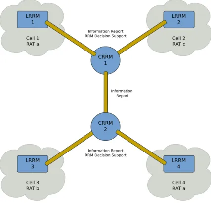
In [2] three CRRM topologies are presented. However, has it already been said, this thesis is only focused in CRRM as a stand-alone server, like it is presented in figure 2.2.
The interactions between LRRM and CRRM involve mainly two types of functions:
informa-tion reportand RRM decision support functions. These two functions are not yet object of standardisation, but their main characteristics are described below:
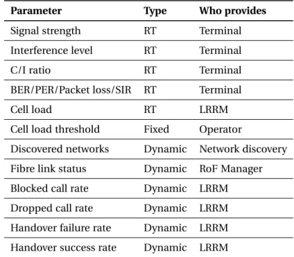
Information report function: allows the LRRM entity to exchange relevant information (which can be dynamic or static) with its controlling CRRM. The reporting may be done periodically, event-triggered or at a given instant when explicitly requested by the CRRM entity [39] (see table 2.1).
The information exchange may also be done between CRRM entities to know the status of other LRRM entities that are not directly connected to the CRRM which requested the information. It is assumed that all this information is controlled by the RNC/BSC (UMTS/GSM).
Measurements within a cell may have different natures regarding their periodicity: • Dynamic measurements: the current cell load, interference measurements,
2.2. OVERVIEW OFCRRM TECHNIQUES 43OF105 LRRM 1 Cell 1 RAT a LRRM 2 Cell 2 RAT c Information Report Information Report RRM Decision Support LRRM 3 Cell 3 RAT b LRRM 4 Cell 4 RAT a Information Report RRM Decision Support CRRM 2 CRRM 1
Figure 2.2.: 3GPP CRRM functional model
• Static information: the overlapping between cells or they belong to a different Hierarchical Cell Structure (HCS) layer, the cell capabilities (e.g., the number of available time slots) or the available QoS, etc.
RRM decision support function: is related with the way how LRRM and CRRM entities interact to take decisions. For example, it is possible that LRRM remains the master of each decision and CRRM only advises (and the contrary is also possible).
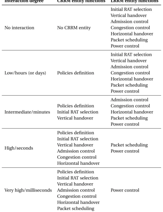
In a heterogeneous wireless scenario, the RRM functionalities for LRRM and CRRM are related with the interaction degree between these two entities, as it is presented in table 2.1. If the interaction degree begins to be higher, more functionalities may reside in the CRRM taking advantage of the global information availability.
44OF105 2. LOCAL ANDCOMMONRRM
Interaction degree CRRM entity functions LRRM entity functions
No interaction No CRRM entity
Initial RAT selection Vertical handover Admission control Congestion control Horizontal handover Packet scheduling Power control
Low/hours (or days) Policies definition
Initial RAT selection Vertical handover Admission control Congestion control Horizontal handover Packet scheduling Power control Intermediate/minutes Policies definition Initial RAT selection Vertical handover Admission control Congestion control Horizontal handover Packet scheduling Power control High/seconds Policies definition Initial RAT selection Vertical handover Admission control Congestion control Horizontal handover Packet scheduling Power control Very high/milliseconds Policies definition Initial RAT selection Vertical handover Admission control Congestion control Horizontal handover Packet scheduling Power control
2.2. OVERVIEW OFCRRM TECHNIQUES 45OF105
Approach based on CRRM Policies
As it was said, the parameters and information exchange over an open interface between LRRM and CRRM entities are not yet standardised. However, this topic is highly important because it would enable the policies exchange from CRRM entity to the LRRM entity. In the proposal of [2] it is assumed that the CRRM entity only acts as an advisor, so the LRRM entities take the final decisions, but based on parameters adjusted by CRRM.
To choose the best target cell further information about the capacity/load situation of possi-ble candidates is provided by the CRRM to the LRRM entity. For example, this information might be a relative ranking of cells.
For this policy-based CRRM, a loose coupling between CRRM and LRRM entities shall be adopted, which means that CRRM policies are valid in the LRRM entity for all handovers until the policy is changed by the CRRM entity. If the policy for a given cell is not changed for more that the time indicated by a certain time-out, then it is assumed that the CRRM entity has failed.
In case of CRRM entity failure it is assumed that the supported LRRM entities can continue with the last available policy, and after some time-out they can fall back to a predefined default policy. In the latter case, the network performance in the affected area would fall back to the case where no CRRM exists (see table 2.1).
While LRRM entities take fast decisions required for each access request or handover request, the CRRM entity works at a slower time scale and provides policies to the LRRM entities whenever an update is necessary. In this sense the frequency for a policy update depends on the traffic variations within the involved cells. The updating frequency can also be subject of configuration.
The CRRM policy approach describes the functional relationship between CRRM and LRRM by three functions:
• CRRM triggers LRRM to report measurement/load information or LRRM reports are initiated by the LRRM entity itself;
• CRRM can inform LRRM about CRRM related information (e.g., cell capacity and load situation of neighbour cells which are not under control of this LRRM);
• CRRM sets load targets for the LRRM functions for which the CRRM entity is responsi-ble.
This can be obtained by the following four procedures: • Measurement initiating procedure (CRRM initiated); • Measurement reporting procedure (LRRM initiated); • Neighbour cell information procedure (CRRM initiated);
46OF105 2. LOCAL ANDCOMMONRRM
CHAPTER 3
Novel CRRM Architecture
A
Sit was said before, in a heterogeneous scenario, different technologies coexist in the same region and their serving areas may be overlapped. In order to efficiently manage the available poll of resources, the 3GPP proposed a new logical entity, the CRRM, in addition to the already existed LRRM. Each considered LRRM is connected to a CRRM that receives measurements and takes decisions related with the global management of available RRUs. Each RAT has its particularities in multiplexing users to access the RF spectrum limiting the interference between them. In WCDMA different users have different and orthogonal codes, since they all use the same frequency to transmit. In OFDMA based technologies, the available bandwidth is divided into orthogonal sub-carriers; these sub-carriers are grouped and form sub-channels, which are distributed among users.With an appropriate management of the radio resources, the particularities of each RAT may be exploited and it is possible to limit the interference, increase capacity and coverage, increase energy efficiency and improve Quality of Experience (QoE) by delivering the agreed (between operator and user) QoS, the Service Level Agreement (SLA).
3.1. Architecture Description
In this architecture, the RRUs are dynamic and centralised managed by the RRM entities: CRRM is concerned with the common tasks and LRRM takes care of particular tasks within each considered RAT. It is considered three different types of LRRM, one per each different technology (WiFi, UMTS and WiMAX).
The CRRM concept in this thesis is aligned with the 3GPP CRRM functional model, presented in figure 2.2. However, this particular implementation tries to take advantage of the cen-tralised information processing and the fact that LRRMs and CRRM are placement inside the same CU.
48OF105 3. NOVELCRRM ARCHITECTURE
In order to deliver the agreed QoS per service, optimising the radio resource usage and impose the policies defined by the network operator, the CRRM will take advantage of VHO mechanism. Thus, in a new SF request, the service characteristics are determined, the actual radio resources are evaluated, a prediction of the new cell load is done admitting that the new request is accepted and, if it is above the cell load threshold, the considered request is transferred to other cell/RAT or it is blocked, otherwise it is accepted (if it is accordingly with the adopted policies).
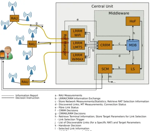
Central Unit RAU RAU RAU a g R o F Ma na ger LRRM WiFi LRRM UMTS LRRM WiMAX MDB CRRM HoF LS SCM Middleware f b h c e j k l d m ... a - RAU Measurements b - LRRM/CRRM Information Exchange
c - Store Network Measurements/Statistics; Retrieve RAT Selection Information d - Discovered Links; MT Measurements; Connection Status
e - Fibre Link Status f - CRRM Decisions g - CRRM/LRRM Decisions
h - Retrieve Terminal Information; Store Target Parameters for Link Selection i - Link Selection Trigger
j - List of Discoverable Links (for a Specific RAT) and Target Parameters k - Handover Decision
l - Selected Link Information m - VHO Trigger towards MIP Core
i
Information Report Decision Instruction
Figure 3.1.: Novel CRRM architecture
In figure 3.1 a general FUTON Middleware architecture, where the RRM entities take place, is presented. The CRRM architecture is described as follow: the Middleware Database (MDB) is the central point (the aggregation point) where the available information is stored (i.e., measurements either performed in the network side or by the terminal, the network statis-tics, profiles and policies); CRRM takes decisions to perform VHO based on policies defined by the operator and select the best available cell/RAT based on all available information retrieved from the MDB, concerning the global network stability and optimisation, inter-ference mitigation, increase capacity and coverage; each LRRM manages the local RRUs based on the instructions that come from CRRM and the local information of its cells; RAUs are constituted by one or more antennas (not limited to a particular technology) and an optical-to-RF/RF-to-optical converter. The RAU measurements are performed by the PHY layer inside each CU that have to send them periodically or upon request to LRRM, which will forward them to the CRRM.
3.1. ARCHITECTUREDESCRIPTION 49OF105
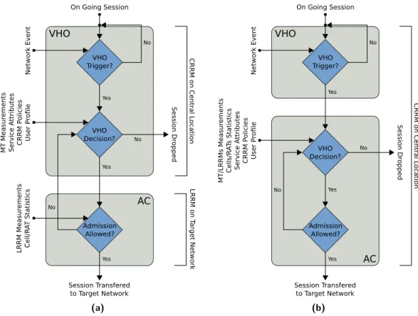
In this solution, two VHO decision points are defined: one at the Handover Function (HoF) and another one at CRRM. This is done because CRRM is related with the radio resource management reasons, while HoF is concerned with the link connection stability and SF QoS. The MDB is also the connection between these two points.
As two decision points are considered, it is easy to predict that two contrary decisions may be taken by the two modules regarding the migration of SFs to another serving cell/RAT. However, in this situation the final decision should be taken by the CRRM. The HoF is more concerned with a single connection or a SF and tries to provide the best QoS as possible and improve the QoE, so it will mainly use the terminal measurements to trigger the handover initiation (e.g., signal strength and application statistics). This type of handover is also known as Mobile Initiated Handover (MIHO). CRRM is concerned with radio network stability and performance. For that, it will mainly use the network measurements (e.g., current cell load) provided by the PHY layer of the CU and the network statistical information (e.g., blocked call rate or call drop rate in each cell/RAT) provided by the LRRM. This handover is known as Network Initiated Handover (NIHO).
When HoF triggers a handover, the CRRM can provide a list rank of the best candidate cells/RATs based on measurements and statistical information to the Link Selection (LS) that will take the final decision for the best suitable link in a certain cell/RAT. However, when CRRM triggers a handover due to network reasons, it is its function to specify the destination cell/RAT, and the LS shall only select the best link inside the specific RAT. In this sense, it is worth clarifying that the term link denotes either a particular RAT, link or channel within a particular RAT. The exact definition will depend on the final LS algorithm.
The goal of LS is to exploit all the information available in the MDB in order to select the best access technology, cell site, or modulation scheme, either for handover sessions or new incoming sessions, delivering the agreed QoS in the best possible way. After the link is selected, the Service Connection Manager (SCM) module will force the terminal to select that link. In this architecture the terminal shall also perform and store measurements in the MDB (that are presented in table 3.1).
MDB is where the measurements and network statistics are stored. It is also the connection point, the bridge, between the HoF, CRRM and all other entities.
Each RAU that serves a certain area is not limited to a particular RAT, and it may support different antennas for different RATs. The received radio signals are multiplexed and trans-parently transported without any information processing from RAUs to the CU through optical fibre. Each optical fibre in its edges is connected with an optical-to-RF/RF-to-optical converter. The RRM entities are only concerned with the radio part of the system, thus the optical part is seen as transparent. In this sense, the functionality of optical fibre is to deliver the radio signals either into the CU or RAUs. Furthermore, it is important to stress that it is not the scope of RRM entities to specify the interface that will map the cells/RATs/RAUs radio resources in each LRRM entity.
In this architecture, the RoF Manager plays an important role since it manages the optical part of the network. Its main responsibilities is to deliver the information if an optical link is
50OF105 3. NOVELCRRM ARCHITECTURE
available or not. This information is relevant in order to select a specific cell/RAT when a handover is triggered.
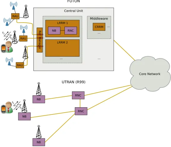
With this topology, there is a LRRM for each considered cell. The advantage is that each cell will in a first instant rely on its local RRM mechanisms to support the intra-RAT mobility. However, apart from the RRM activities between the BSs and terminals, the local radio management functionalities of the legacy RNC (the UMTS case) and BSs are now moved to the CU, which means that part of local radio management will be remotely done, which may be far away (introducing delays that can limit the decisions validity). This new scheme will not completely break the previous rules or policies defined by operators in the legacy systems (compatible with 3GPP standards); however, instead of being implemented in a distributed fashion (BSs and RNCs) they are centrally implemented in the CU.
Central Unit LRRM 1 RNC NB LRRM 2 ... RAU RAU RAU R o F Ma na ger CRRM Middleware ... ... ... RNC RNC NB NB NB Core Network f1 f2 UTRAN (R99) FUTON f1 f2
Figure 3.2.: LRRM placement in CU versus legacy system (UTRAN)
As it can be seen in figure 3.2, the NB and RNC functionalities are moved to the logical entity LRRM inside the CU. However, with the introduction of CRRM entity, the decision taken moves to the CRRM while the local implementation still remains in the LRRM.
3.2. DESIGNPRINCIPLES OFCRRM 51OF105
3.2. Design Principles of CRRM
In this section it is described the concepts used to develop the presented CRRM architecture and its algorithms. In the end of this section, it is presented a small table that summarises the followed choices when designing the CRRM algorithms.
3.2.1. Functionalities of LRRM and CRRM Entities
RRM functionalities may be divided into two categories: network-based RRM and connection-based RRM [11]. Network-connection-based RRM includes: AC, CC, and PS; and it applies to how users affect performance and network load. Connection-based RRM includes: handover control and PC; and it deals with the performance of the connection on an individual level.
Regarding the local and the common radio management functionalities, they are closely related with the interaction degree between LRRM and CRRM entities. Table 2.1 clearly divides those functionalities considering the interaction degree. Thus, if the interaction is considered low, more functionalities reside in the LRRM; however if it is considered very high, almost all functionalities reside in the CRRM entity (the exception is the PC that always reside in the LRRM).
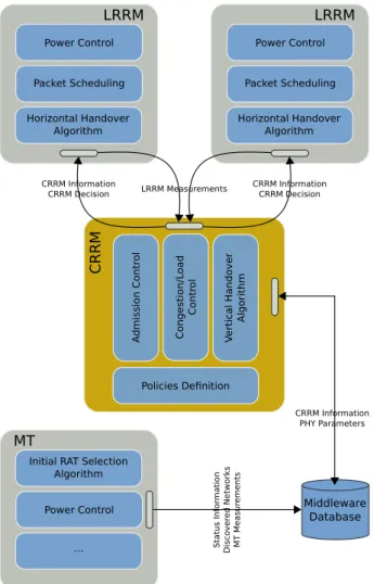
One key aspect of this new architecture is the centralised information processing and de-cision taking at the CU. Since both LRRM and CRRM entities are placed in the same CU, they are close to each other which greatly reduces the delay in messages exchange. This closeness leads the interaction degree to be considered as high (seconds). This way, more RRM functionalities are considered common (reside at the CRRM), which may optimise the system due to the global information availability. In figure 3.3 the local and common radio management algorithms and functionalities are divided per entity.
Taking into account the scope of this thesis and the nature of supported technologies, some adjustments were done when comparing figure 3.3 with table 2.1, namely the initial RAT selection is done at the terminal side and the HHO is done by the LRRM. HHO is locally done between cells within the same RAT because it is envisaged the compatibility with the already deployed systems. Regarding the initial RAT selection, it is done in the terminal side because when it switches on no service has already been requested, so no radio management must be done. The following sections only consider the RRM techniques that make part of CRRM.
52OF105 3. NOVELCRRM ARCHITECTURE Packet Scheduling Power Control Horizontal Handover Algorithm LRRM Packet Scheduling Power Control Horizontal Handover Algorithm LRRM C RR M A dmiss ion C on tr o l C o n ges tio n /L oad C o n tr ol V er ti ca l Han dover Al gor it hm Policies Definition LRRM Measurements CRRM Information
CRRM Decision CRRM Information CRRM Decision
Middleware Database
Power Control
...
MT
Initial RAT Selection Algorithm CRRM Information PHY Parameters Sta tu s In fo rma tio n Di scover ed Netw o rk s MT M eas u rem en ts
Figure 3.3.:RRM functionalities divided per entity
3.2.2. CRRM based on Vertical Handover
For an operator that owns sites with different RATs it would be useful to manage and dis-tribute users among its infrastructure in a certain optimal way so that more users may be accommodated, while each of them would receive the contracted QoS per SF and, at the same time, limit interference and greatly reduce the congestion risk. Traffic balancing strate-gies based on VHO are one of the possible procedures to optimise the network without compromising QoS.
In legacy systems, the basic strategies for VHO are only motivated by coverage issues to guarantee the continuity of service. In B3G networks, more sophisticated strategies shall be adopted, taking into account not only coverage issues, but also the capacity criteria, the required QoS per service flow or service classes and the operator policies [24].