Cop yrigh t Q 1999 Taylor & Fr an cis 1040 ± 7790rrrrr99 $12.00 H .00
NUMERICAL PROCEDUR E FOR THE C OMPUTATION
OF FLUID FLOW WITH ARBITRARY
STRESS-STRAIN RELATIONSHIPS
Pau lo J. OliveiraDepartam ento de Engenh aria Electromecanica, Universidade da Beira Interior,Ã 6200 Covilha, PortugalÄ
Fernando T. Pinho
Centro de Estudos de Fenom enos de Transporte, DEMEGI, Faculdade deÂ
Engenharia, Universidade do Porto, 4099 Porto Codex, Portugal
A finite-volume method is presented th at allows for general stress-strain constitutive equ ations to be incorporated into a standard momentum ± pressure-correction procedure. The method is sequenti al and segregated in nature, the various equ ations for mass and momentum conservation and for the evolution of the stress tensor are solved following a predefined order, and one of its features is the use of nonstaggered, and generally nonorthogon al, computational meshes. Two types of constitutive equations are used to test the method: the standard explicit and algebraic Newtonian model, and one of the simplest implicit differential equ ations, the upper-convected Maxwell model. In spite of its apparent simplicity, this latter model is known to pose the most severe numerical difficulties. However, the results in this article show the method to be effective in solving the equations for the flow of Newtonian and viscoelastic fluids through abrupt plan ar contractions with an area reduction of 4 to 1, one typical benchm ark problem. The results are compared with available data and with solutions from a standard and validated code, and good agreement and consistency is found. A new formulation to evalu ate stresses at cell faces is presented and shown to lead to improved results.
1. INTR ODUCTION
Most procedures to calculate fluid flow are based on Newtonian constitutive stress-strain relationships that are implicitly embedde d into the flow equations, resulting in the usual Navie r-Stoke s equations. Howe ver, ve ry often real fluids exhibit non-Ne wtonian viscoe lastic be havior, and in such case s it is ne ithe r advan-tageous nor always possible to find an explicit relation be tween the stress tensor and ve locity gradie nt components to substitute into the momentum equations. As a conseque nce, it is useful to deve lop nume rical procedures adequate for ge ne ral stress tensors, which are often relate d with the flow kine matics in a complex and implicit manne r via additional differential equations, thus separating the stress calculation from the solution of the momentum equations. The de velopme nt of such a method is the scope of the present article. The stress-strain relationships to
Receive d 2 October 1998; accepte d 9 De ce mber 1998
The authors acknowledge the financial support of Junta Nacional de Inve stigacË ao Cientõ fica eÄ Â
s .
Te cnologica JNICT under project PBICÂ r1980. The authors are listed alphabetically.
Address correspondence to Dr. P. J. Oliveira, Universidade da Beira Interior, Departame nto de EngaE lectromecanica, 6200 Covilha, Portugal. E-mail: [email protected]Ã Ä
NOMENCLATURE
a , aP F coe fficients in the discretized d i j identity tensor
s .
e quations d x,d y ce ll sizes normalized asd xrH
bl i coe fficients in the discretized stress d t time step w x
e quations D ul difference between u values along
B, Bl i are a, i component of are a of a ce ll direction l surface aligned with directionj l l re laxation time
s .
De De borah number sl UrH m viscosity coe fficient
f , fx y e xpansionrcontraction factors to n ce ll volume
distribute cell spacing r density
Ff m ass flow rate across cell face f j l general coordinates
H half-width of downstream ch anne l t i j Cartesian components of the e xtra
L , L1 2 lengths of upstream and stress tensor
downstream channels C stre am function value
N1 primary normal-stress difference
p, P pressure, normalized pressure Su bscripts an d Su perscripts
ss prs m UrH..
s . s .
Re Reynolds number sr UHrm i, j, k Cartesian components from 1 to 3
S source term in the discretized l, m directions along ge neral
s .
e quations coordinates from 1 to 3
t time P, F generic control volume and
s .
Ti j normalized stress components neighbor F from 1 to 6 sst i jrs m UrH.. f ce ll face between ce lls P and F
s . s .
u , u ,i v Carte sian velocity components varie s from 1 to 6
s streamwise and cross-stream n , n q 1 denotes previous and prese nt .
components time level, re spectively
Ä
U average velocity in downstream special cell-face interpolation
channel linear interpolation
s . s
xi x, y Carte sian coordinates stre amwise 9 divided by central coefficient aP
. s
and cross-stream * intermediate value s calculated
.
xR re circulation length implicitly
be considered will eithe r follow the Newtonian viscosity law, but in this case with the stress compone nts evaluate d from inde pende nt equations and then incorpo-rated into the stress-diverge nce term of the momentum equations, or are give n by a line ar differential equation for the evolution in time of the stress tensor. Future work will conside r the case of quasi-line ar and nonline ar stress-strain relations.
The de ve lope d numerical procedure is of the finite -volum e type along the w x
lines expose d by Patankar 1 , but incorporating modern technique s such as the use of nonstagge red and nonorthogonal meshe s which allows for greate r ve rsatility in
w x
terms of flow geometry 2, 3 . The important contribution that made possible the widespread use of the nonstagge red mesh arrange ment was the nove l interpolation
w x
scheme of Rhie and Chow 4 for de termining ve locity value s at cell faces, and a w x
similar philosophy has be en recently advance d by Olive ira et al. 5 for the proble m of de termining stress value s at cell faces. We shall use he re an improvement of this latte r method to inte rpolate the stress compone nts require d in the stress-dive rge nce term of the line ar momentum equation. The numerical procedure is then applie d to a typical proble m often used as a test case in the non-Ne wtonian
w x
s .
upper-convected Maxwe ll mode l UCM through a 4-to-1 planar contraction. This particularly simple ge ometry doe s not require the nonorthogonal capability of the procedure , a matte r left for future inve stigation. It pose s, howeve r, seve re
numeri-w x
cal difficultie s, especially for the UCM fluid 10, 11 , because of unbounde d stresses at the reentrant corner with a ve ry inte nse localize d growth rate for all stress compone nts; furthermore, for this fluid model the resulting flow fe atures are
s w x w x.
not ye t fully understood see revie ws in 11 and 12 .
2. GOVERNING EQUATIONS AND CONSTITUTIVE MODELS
The basic equations to be solve d are those expre ssing conse rvation of mass, - r uj
s .
s 0 1
- xj
and of line ar momentum,
- r ui - r u uj i - p - t i j
s .
q s y q 2
- t - xj - xi - xj
In these equations u is the velocity component along the Carte sian axis x ,i i r is
the fluid de nsity, and the total Eule rian stress tensor s i j has be en de composed
into an isotropic pre ssure term plus an extra stress tensort i j, as s i js ypd i jq t i j,
whe re d i j is the identity tensor. Here we will be concerned with incompre ssible and
steady flow, and the main de pe ndent variable s to be solve d for are the ve locity components, the pre ssure, and the stress components. The ve locity compone nts
s .
result from the momentum equation 2 , for incompressible flow the pressure is an arbitrary field required to constrain the ve locity fie ld so that it conforms to
s .
equation 1 , and the stress components must be give n by a rheological constitutive equation.
w x
In ge neral, the equation for the stress tensort i j is of the hype rbolic type 13
w x and is derived eithe r from continuum mechanics or from kine tic theory 14 , whe re force balance s acting on simplified mode ls of molecular be havior are utilize d. The precise form of these equations varie s according to the fluid considered, but must respe ct some ge neral rules such as obje ctivity, realizability, etc., and must also provide physic ally realistic responses and preferably be supporte d by kine tic theory argume nts. In this article , two constitutive models are considered. First, and in order to compare the pre sent method with standard proce dures, we consider the well-known Newtonian mode l give n by the alge braic explicit stress-strain relation-ship,
- ui - uj 2 - uk
s .
t i js m
t
- q/
y m d i j 3xj - xi 3 - xk
whe re m is the constant dynamic viscosity of the fluid, and the ve locity dive rge nce
ne verthele ss retaine d be cause it is not exactly zero in the numerical approxim ation whe n the nonstagge red mesh arrangement is utilized. Beside s, inclusion of this term le ads to more accurate results, as will be shown in Se ction 4.
The second constitutive equation considered for the extra stress compone nts
s .w x
t i j is the upper-convected Maxwe ll model UCM 13 ,
- t i j - uk i jt - ui - uj 2 - uk t i jq l
t
q/
s mt
q y d i j/
- t - xk - xj - xi 3 - xk - uj - ui s . q l tt
i k q t jk/
4 - xk - xkwhe re m can still be seen as a constant viscosity coefficient and l is anothe r
parame ter of the mode l with the dimensions of time and commonly calle d the s .
relaxation time of the fluid. Equation 4 is one of the simple st mode ls to represent viscoe lastic fluid behavior, and it is note d that the Newtonian mode l is obtaine d as
a spe cial case of the UCM model whe n l is set to zero. Howeve r, in the gene ral
case of l / 0, the UCM equations introduce considerable complication into the
proble m of de termining the motion of a fluid: six new implicit differential equa-tions on the stresses have to be solve d in conjunction with the momentum and
s .
mass conservation equations. Furthermore , although Eq. 4 is line ar on the
s .
stresses t i j, when couple d with Eq. 2 , implicit nonline arities will arise through the
terms with ve locity gradie nts.
3. NUMER IC AL METHOD
The diffe rential equations are integrated ove r control volum es in ge ne ral
s .
body-fitte d computational meshes j l with the help of standard discretization
w x
procedure s 1, 2 . The depe nde nt variable s are the three Cartesian ve locity compo-ne nts, the pressure, and the six Cartesian stress compocompo-nents; all the se variable s are stored at the cente r of the control volume s, as implied by the nonstagge red mesh arrange ment adopte d he re. Spe cial procedures are thus require d to avoid
pres-w x w x
sure] velocity decoupling 4 and stress] velocity decoupling 5 . Details of the
discretization procedure can be found in the latter reference and he re, for the sake of concisene ss, only the constitutive equation will be tre ate d with more de tail.
s . Discretization of the continuity Eq. 1 give s
6 s . F s 0 with F s
s
r B uÄ
.
5p
f fp
f j j f f j s .expre ssing mass conservation: the sum of the outgoing mass flow rates Ff over
the six faces de limiting any give n cell must vanish. The tilde over the ve locity is used to de note a spe cial Rhie-and-Chow type of inte rpolation; the pre cise form is
w x
as give n in 15 . Here, and in the following, the i compone nt of the are a of any cell
surface oriented along direction j l is de noted B ; if this surface coincide s with anli
actual cell face with dire ction j f, the n we write B as the i component of that cellf i
s s .1r2.
After discretization over any cell P, the momentum equation can be written under the standard line arize d form:
6
s . s . s .
aP ui Ps
p
aF ui Fq Su 6i F
whe re the coefficients aF are made up of conve ctive and diffusive contributions,
whose precise form de pends on the differencing schemes adopte d, and the central coefficient is r n s . a sP q a0 with a s0
p
aF 7 d t s .the sum being again over the six cell neighbors F surrounding the cell P under
conside ration. Here d t is the time step used in the time-marching computations.
s .
The source term in Eq. 6 results from all contributions in the momentum equation that have not be en include d into the coefficients and, from inspe ction of
s .
Eq. 2 , these are
s .
S s Su u q Su q Su q Su q Su 8
i i y p r e s i y str e ss i ydt i y H O S i y di ff
for the pressure gradie nt, the stress dive rgence, the inertia term, a possible term
s .
arising from use of a high-orde r diffe rencing scheme HOS for convection, and an adde d diffusion term that cancels exactly the diffusion contribution in the
coeffi-w s .x
cients, since there is no explicit diffusion in the original equation Eq. 2 .
s . s .
The discretized stress equation 4 can be cast into a form similar to Eq. 6 as 6 t s . t s . s . aP t i j s
p
aF t i j q St 9 P F i j Fwith the central coefficient now give n by l n
t t s .
a sP n q q a0 10
d t
and the other coefficients compose d only of conve ctive fluxe s due to the abse nce of s .
diffusion in the constitutive equation 4 . It is straightforward to arrive at the source term in the stress equation after transforming the Cartesian de rivative s in
s .
Eq. 4 into de rivative s with respe ct to the ge neral coordinates, by making use of
the rule -
r
- x s Ji y1b l i-r
- j l, and re alizing that in the discretized equations theJacobian J be comes a cell volum e n and the metric coefficients b l i be come are a
w x
components Bl i 16 ; that source term can the n be written as
3 2 w x w x w x S st i j
p
t
bl i D u q b D uj l l j i l y 3t
p
m Blk D uk l/
d i j/
l k P l n n s . s . q t i j q St 11 P i j y H O S d t2
whe re the term multiplie d by 3 results from ke eping the div u term in the
Newtonian part of the constitutive equation and the b coefficients are give n by
s .
b sl i m B ql i l
p
Bl k i kt 12k
One key fe ature in the nume rical procedure is the de termination of the stress
s .
components at cell faces t
Ä
i j required for the dive rge nce term in the momentumequation, that is,
6
s .
Sui y s tr e sss
p
t
p
Bf j i jtÄ
/
13f j f
In order to avoid stress-ve locity decoupling and along the lines of the procedure w x
give n by 5 , the face stresses are de fined as
2 Xt X X X s t
Ä
i j.f’p
aFst i j.Fqp
t
b D ul iw jxlq b D ul jw ixly 3p
m Bl kwD ukxld i j/
F l/ f k f 2 l n X X X n XÄ
w xÄ
w xÄ
w x s . q b D uf i j fq b D uf j i f y 3p
m Bf k D uk fd i jqt /
d t 9 t i j Pq St i jy HOS k s14. whe re the ove rbar here de notes line ar inte rpolation at the cell face position, andthe prime de notes division by the central coefficient atP. It is simple r to use the
s .
following expression, obtaine d after dividing Eq. 9 by the central coefficient, applying line ar ave raging to it, and subtracting the resulting equation from
s . Eq. 14 : 2 X X X st
Ä
i j.fst /
t i j f y b D ut
f iw jxfq b D uf jw ixf y 3p
m Bf kwD ukxfd i j/
k 2 X X XÄ
w xÄ
w xÄ
w x s . q b D ut
f i j fq b D uf j i f yp
m Bf k D uk fd i j/
15 3 k with m B qf i lp
Bf j i jtt
j/
B f i f X XÄ
Ä
s . b ’f i t and B ’f i t 16 s . s . n f aPr
n P n f aPr
n P s .Expre ssion 15 is essential to avoid the problem of stress] velocity decoupling and
w x is only slightly different from that proposed in our previous work 5 , ye t it improve s the results, yie lding be tter stress inte rpolation whe n the mesh spacing change s abruptly, as will be shown be low.
Solution Procedure
The sets of discretized equations are solve d in a sequential manne r following a pse udo-time -marching approach de scribed be low, whe re ne w or inte rmediate value s are de note d with an aste risk, and value s from the pre vious time step with inde x n.
s U. w s .x
1. Obtain cell-ce nte red stresses t i j from the implicit equation Eq. 9 ,
6 n U U t s . t s . s . aP t i j s
p
aF t i j q Ss
t.
17 P F i j Fand store the central coefficient atP.
s . s .
2. Compute cell face stresses t
Ä
i j from Eq. 15 , base d on newly obtaine dstresses t i jU, the stored central coefficient atP, and velocity gradie nts at the
previous time step.
3. Solve for the Cartesian ve locity compone nts at cell cente rs, uUi, from the
w s .x
discretized momentum conservation equation Eq. 6 , 6 n U U s . s . s . s . aP ui Ps
p
aF ui Fq Su 18 i F s w x.4. Obtain cell face velocitie s see 15 and form the corresponding mass flow
s .
rates Eq. 5 ,
FfUs
p
s
r B uf jÄ
Uj.
f js
5. Solve the pressure-correction equation following the SIMPLEC algorithm
w x w x .
of 17 ; see 15 for the time-marching ve rsion and correct the pressure
fie ld, p*, the ve locity fie ld, u**, and the mass flow rates, FfU U, which will
now satisfy the continuity constraint.
6. Check for conve rge nce to a ste ady state, whe n the norm of the residuals of
s y4.
all equations has falle n be low a prescribed tole rance 10 ; otherwise,
s .
take the variable s as pe rtaining to a ne w time le ve l n q 1 and go back to step 1.
Implicit solution of the line ar sets of equations in steps 1, 3, and 5 is carried w x out by applic ation of standard pre conditione d conjugate gradie nt methods 16 .
4. R ESULTS
The numerical method described above was implemented into a
computa-tional code that we shall de note as the ``stress’’ code , and was the n applie d to a
typical problem: the flow of Newtonian and UCM fluids through a planar contrac-tion with a cross-seccontrac-tional are a ratio of 4 to 1. This particular flow has be en often
w x w x w x
and Crochet 6 , Webste r and co-worke rs 10, 11 , Xue et al. 12 , to name only a few of the rele vant works. The flow is completely de scribed by two nondime nsional parame ters, the Reynolds and Deborah numbe rs. The former is define d he re with
the ave rage ve locity U in the downstre am channe l of half-width H, Re s r UH
r
m ,and the latte r give s an indication of the elasticity of the UCM fluid, De s l U
r
H.Results are first presente d for the Newtonian case, De s 0, allowing
compar-ison be tween the present ``stress’’ code and a ``standard’ ’ Navie r-Stoke s solve r
s w
which has be en used in previous work and is by now sufficiently validate d e.g., 15, x.
16, 18 . This standard code solve s the momentum and continuity equations in w x
collocate d meshes and is essentially similar to that de velope d by Pe ric 2 . Agree-
Â
ment be tween the results of the two code s will give an indication of the correct imple mentation of the method de velope d to handle ge neral stress equations.
Then, the flow of the UCM fluid with increasing degree of elasticity will be conside red, mainly for Re s 1. Here we will concentrate on the streamline pat-terns and on the stress fie lds, which show interesting phe nome na that are not present in the Newtonian case. Whe re possible , comparisons are made between our predictions and others from the lite rature.
Newtonian Fluid
The contraction ge ometry has been mappe d with three successive ly refined computational meshe s, of which Figure 1 shows a zoomed portion of the fine st
smesh 3 . The mesh is orthogonal but nonuniform , with incre ase d concentration of.
cells in the are a of the contraction, especially around the reentrant corner whe re the stress gradie nts are expected to be high. For the mesh of Figure 1, the
ws .
minimum nondime nsional cell size is 0.01 in both the x and y directions d x
r
H mins . x
and d y
r
H min ; this value is double d for the medium mesh 2 and double d againfor the coarse mesh 1. In e ach mesh the cell size varie s following a ge ometric
s .
progre ssion at constant ratio f ’x d xiq 1
r
d xi inside e ach subblock use d togene rate the overall mesh. The f and fx y were carefully chosen to guarante e a
smooth cell-size variation at boundarie s between the patche d subblocks. In orde r
s . s .
to go from mesh 1 the coarsest to mesh 2 the medium , and from mesh 2 to mesh
s .
3 the fine st , the numbe r of cells along the x and y dire ctions inside each
s
subblock was double d and the corresponding expansion
r
contraction ratios f andx.
fy were root-square d. With this proce dure a consistent refine ment is achie ved in
s w x.
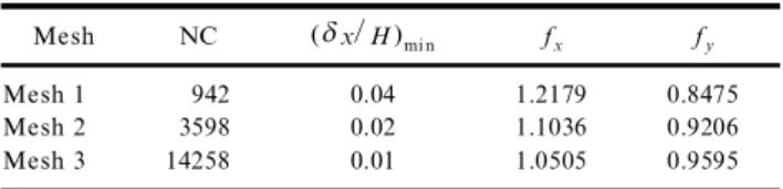
these nonuniform meshe s see 19 , with all mesh spacings being approxim ately halve d at each step and enabling error estim ation through Richardson’ s extrapola-tion to the limit. Other details of the meshes are give n in Table 1, whe re NC is the total number of cells and where the inle t and outle t channe l le ngths were taken as
L s 20 H and L s 50 H, respectively. These le ngths were found sufficient to1 2
achie ve fully deve loped conditions at the outle t in both the Newtonian and in all the elastic flow cases.
The results to be give n were obtaine d with the fine r mesh unless stated othe rwise. The effect of mesh refine ment can be asse ssed from the value s for the
s .
length of the recirculation zone in the salie nt corner xR and the amount of flow
s .
in the eddy scaled with the inlet flow rate C R give n in Table 2. They were
s .
Figu re 1. Z oomed view of the finer me sh
Table 1. Mesh ch aracteristics s . Mesh NC d xrH mi n fx fy Mesh 1 942 0.04 1.2179 0.8475 Mesh 2 3598 0.02 1.1036 0.9206 Mesh 3 14258 0.01 1.0505 0.9595
Note : f and f are for the subblock in the downstream channel.x y
Table 2. Eddy characte ristics with mesh re finement
y 4 s . y 4s . s . Me sh C R= 10 xRrH N1m a x C L C R= 10 UDS xRrH UDS Mesh 1 4.83751 1.1838 2.2672 5.29766 1.2073 Mesh 2 4.39882 1.2020 2.2912 4.60744 1.2141 Mesh 3 4.37856 1.2072 2.2896 4.48108 1.2134 Limit 4.37975 1.2090
sUDS for the convective terms in the momentum equations. There is little.
s .
difference be tween the results of the two schemes espe cially for x , an expe ctedR
s
outcome for this low-Reynolds-num ber flow recall that Re s 1 and so the local .
cell Reynolds number is much lowe r still , but the CDS being ide ally second-orde r accurate enable s be tter Richardson extrapolation.
Based on the value s in Table 2, the error estimate for the simulation in the fine mesh is 0.15% and the medium mesh is able to give results for eddy size and inte nsity to within 1.0% . Richardson’ s the ory give s the order of the numerical
ws . s .x s .
approxim ation as p s ln xR 2 y xR1
r
xR 3 y xR2r
ln 2 s 1.81, base d on the xRvalue s in the three meshes, in good agreement with the the ore tical value of 2 for the central differencing scheme. Me sh 2 and mesh 3 also show good superposition of local quantitie s, as exe mplified in the profile of the first normal stress difference
wN s T1 x xy T , where T are normalized stresses, T sy y i j i j t i j
r
s m Ur
H.x along thes .
centerline y s 0 , give n in Figure 2. The maxim a of the se profile s are give n in
Table 2, use ful data for be nchmarking. Similar conve rge nce with mesh refinement has be en found for other variable s, such as ve locity and stress compone nts, but this comparison is not shown he re for conciseness. For the viscoelastic fluid obeying the UCM constitutive equation the re is a tendency for finer meshes to be required as the Deborah number is incre ase d, due to the resulting steepe r stress gradie nts. However, at De s 2 the results with mesh 2 and mesh 3 are still not too diffe rent, as shown in Figure 2, although accuracy to the same leve l attaine d by the Newtonian runs may require fine r meshe s.
The results for Newtonian fluids obtaine d with the ``stress’’ code are in
excellent agre ement with those obtaine d with the standard code , which yie lds
C s 4.3869 = 10y4 and x
r
H s 1.2076 for mesh 3. It has also been checke d thatR R
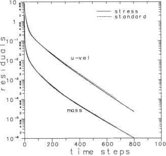
profile s of local variable s at various locations agre ed ve ry closely, and consequently we may conclude that the imple mentation of the stress method has been done correctly. In terms of conve rge nce rate, Figure 3 compares the history of the residuals for the two code s and for the combination of parame ters Re s 1, De s 0,
Figu re 2. Effect of mesh refinement on the primary normal
s .
stress difference along the centerline De s 0 and 2 .
Figu re 3. Decay of the norm of the residuals of the u momentum
and continuity equations for the ``stress’’ and``standard’’ proce-dures.
s .
mesh 2, d t
r
Hr
U s 0.01, with a converged solution be ing assumed whe n thenormalize d residuals of all equations fell be low a tole rance of 10y4. These
residuals are define d as the l norm of the alge braic equations to be solve d, with1
all terms shifted to one side of the equal sign, and should essentially tend to zero as the solution is approache d. Figure 3 shows that the new method follows an ide ntical convergence path to the standard one , and the number of time steps to
s .
the solution is only slightly highe r 798 compared with 674 , be cause the residuals
s .
stopping criterion and tend to lag be hind those for the momentum and mass conservation equations. Still, for an ide ntical stopping criterion, the CPU require d by the ne w method whe n applie d to a Newtonian fluid is only 18% large r than that of the standard proce dure, a re asonable computing time ove rhead to pay for the adde d advantage of choosing any gene ral constitutive relation. Naturally, the use of a different constitutive equation will require additional computer time.
It is inte resting and rele vant at this stage to corroborate the point made in
2
Se ction 2, that inclusion of the y 3 div u term in the stress equation for the
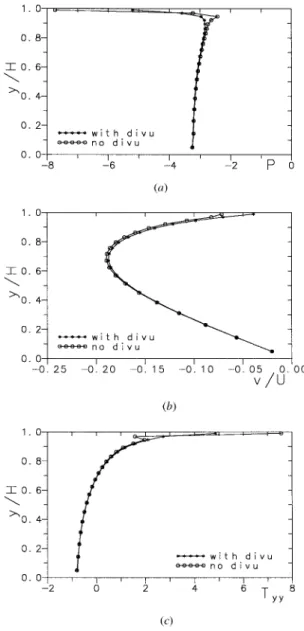
Newtonian fluid tends to give more accurate results and is also be tter at reducing the computing time. Figure 4 a compares the normalized pressure variation P ’
s .
p
r
m Ur
H at the entrance to the smalle r channe l, just downstre am of thecontraction plane , with and without the div u-term and using the medium-sized mesh. When the div u term is not include d to force a tracele ss de viatoric stress
s
tensor, there are some perturbations in the pressure profile ne ar the wall at .
y
r
H , 1 . Similar unphysical pe rturbations are obse rve d in the late ral compone nts . s .
of the ve locity v
r
U Figure 4 b and the norm al stress compone nt Ty y Figure 4 c ,but the y are suppre ssed whe n the div u term is included in the stress tensor. In gene ral, not including this term le ads to highe r maximum le ve ls of pre ssure and
w s . x
stress components e.g., Tx x max incre ase s from y5.1 to y7.4 , which typically
occur close to the reentrant corner where the high gradie nts are localize d, and the
s
computing time increases by 30% and 15% in the two tested case s Re s 0.01 and .
1, respe ctive ly .
Viscoelastic Fluid
We turn now to the more complicated case of the implicit diffe rential UCM
w s .x
constitutive equation Eq. 4 , which was solve d with the proce dure outline d in w
Se ction 3. Since the stress contribution to the momentum balance the divt term
s .x
give n by Eq. 13 is treate d explicitly in the numerical method, so that it lags in
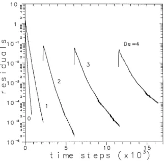
time as the solution is re ache d through a sequential treatment of the various equations, it is expe cted that convergence to a ste ady state will be slower than for the Newtonian fluid. This is inde ed the case as shown in Figure 5, which give s the history of the residuals for the slowest variable , for various runs with increasing
s .
value s of De. The runs for the Newtonian fluid De s 0 and for De s 1 have been started from an initial condition of uniform ve locitie s and vanishing stresses and pressure everywhe re; the othe r runs have be en restarted from the corresponding solution at lower Deborah numbe r. This procedure is convenie nt to reduce computer time but was not found ne cessary to guarante e convergence. All runs in
s y2 .
Figure 5 used the same time step d t s 10 H
r
U in spite of increased elasticity,an indication of the robustne ss of the present numerical method. The conve rge nce rate, proportional to the inclination of the curve s, is reduced as De incre ase s, and so computations at high De will require more time steps for a ste ady solution to be re ache d. This situation is common to all methods reporte d in the non-Ne wtonian
w x
literature, most of them of the finite -ele ment type 6, 8] 11 , and with the drawback
that those methods often could only obtain solutions at very low Deborah numbe rs
se.g., Yoo and Na 7 , Dew x
-
1.04; Carew et al. 8 , De ( 2; Sato and Richardson 9 ,w x w x. w x
De ( 2 . Marchal and Crochet 6 could attain De s 6, but with ve ry coarse meshes.
Figure 4. E ffect of including the div u term in the
constitutive equation: transve rse profiles at x s 0.01 H of s .a normalized pressure, bs . vrU, and c normal stresss .
T .y y
A comparison of some of the results of the literature and those of the pre sent stress method is carried out in Table 3. The exte nsion of the recirculating zone
w x
predicted by 9 , utilizing meshes with a minimum spacing of 0.025 and 0.05, w x
compared well with the present pre dictions, and so did those of 11 for the low-De range. For the high-De numbe r range , howe ver, these latte r authors used a mesh
s .
s .
Figure 5. Convergence history for the Ne wtonian De s 0
and various UCM fluid flows.
Table 3. V alues of xRrH: comparison with other calculations
aw x aw x b
De Sato 9 , Re s 1 Ours, Re s 1 Matallah 11 , Re s 0.5 Ours Re s 0.5
0 1.145 1.213 1.318 1.341 1 1.000 0.988 1.114 1.189 2 0.927 0.833 1.0 1.175 3 } 0.784 1.0 1.319 4 } 0.851 1.0 1.550 5 } 1.081 } 1.784 6 } 1.339 } } 8 } 1.755 } } aOldroyd-B model. bWith mesh 2.
and that may explain the fact that the ir pre dictions of xR tende d to a constant
value for De 0 2.
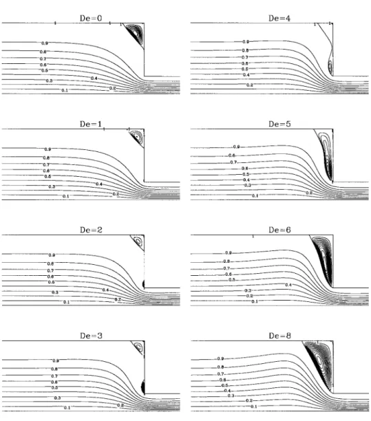
Some of the pote ntial of the present method for the study of viscoelastic fluid flow is illustrated by Figure 6, which shows the streamline patterns for increasing
s .
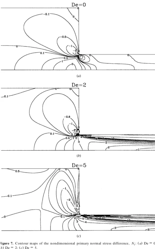
De from 0 to 8 at constant Re s 1, and by Figure s 7 and 8, which show some of the corresponding contour plots of the nondime nsional normal-stress difference
s N1.and shear stress Ts x y.fie lds, respectively. Care ful analysis of the se figures and
othe r data from the solution fie lds, a matte r outside the scope of the pre sent article , may explain some of the peculiar feature s observe d in expe riments with viscoe lastic fluids. The stre amline patte rns in Figure 6 show the appe arance of a lip
Figu re 6. Streamline patterns of UCM fluids for increasing Deborah numbers, at constant Re s 1.
sIso-levels in the e ddies are e qually spaced, with d C = 10 s 0.05 for De s 0] 3; 0.5 for De s 4] 6;3
. and 1.0 for De s 8
the lip vorte x at De ( 4, the eventual merging of the two vortice s at De , 4] 5,
and the subse que nt growth of the single remaining vorte x. The flow patterns at low De are in good agre ement with the recent simulations for an Oldroyd-B fluid of
w x s .
Matallah et al. 11 mainly so for De s 1 to 3 , which also show the onse t of the lip
s w x
vorte x that has been quite elusive in previous works e.g., Sato and Richardson 9 ; w x.
see also review in 11 . We may also add that the flow feature s seen in Figure 6 are not just a peculiar effect resulting from the the ore tical UCM model and abse nt from the reality; in fact, similar vorte x-re late d phe nome na have be en obse rved
s .
s .
Figure 7. Contour m aps of the nondimensional primary normal stress difference, N : a De s 0;1
s . s .
Figure 8. Contour m aps of the nondimensional shear stress, T :x y a De s 0; b De s 2; s .c De s 5.
sin round contractions. w x20 . The sketches of vorte x growth mechanisms give n by
w x s .
Boger et al. 21 see the ir Fig. 10 , base d on visualizations of viscoe lastic entry
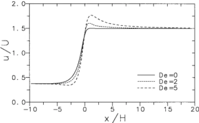
flows, are closely emulate d by the succession of stre amline patterns in Figure 6. Lip vortice s, corne r vorte x enhancement, and the othe r differences between Newtonian and viscoelastic flow patte rns seen in Figure 6 results from distinct stress structure, as can be infe rred from Figures 7 and 8. The main differences are the very high normal and she ar stresses that build up around the reentrant corner for viscoe lastic fluids, and the enhancement of the elongational flow along the
centerline evide nt in Figure 9, and caused by a large and positive N at the1
entrance to the contraction. The stress field forces the viscoe lastic fluid to be more de flected toward the cente rline than the Newtonian or the le ss elastic fluids, whe re
the flow is further accelerated by the positive Tx x gradie nts; as a conseque nce the
axial velocity profile s of the viscoe lastic fluid at the contraction plane are more uniform, and the centerline velocity reaches highe r value s than those of the Newtonian case and may eve n go be yond the fully de velope d value in the down-stream channe l, as shown in Figure 9. The centerline ve locity ove rshoot effect has
s w x. s w x.
be en obse rved in other simulations cf. 6, 12 and also experimentally e.g., 22 ,
and the increase relative to its fully de velope d value is in reasonable agreement
s
with othe r works where diffe rent fluids have been used he re we obtain 2.8% , w x
7.1% , and 17.8% for De s 1, 2, and 5, respective ly; Xue et al. 12 got 4% for
w x .
De s 1.6; Marchal and Crochet 6 got 22% for De s 4.7 .
We end this work with a comparison between the new formulation used to
s .
obtain stresses at cell faces give n by Eq. 15 and that proposed in a previous work
w x5 . The main diffe rence be tween the two formulations lies on the way inte
rpola-tion is done, which affe cts the results when nonuniform meshe s are utilized. In the former formulation the forces acting on a surface across cell centers were
interpo-s .
lated directly with arithme tic ave raging to the cell faces, thus the b were give nl i
w s .x
by Bl i jt nj cf. Eq. 16 ; howeve r, it seems more correct to interpolate the stress components and the n obtain forces at cell faces via the usual tensorial relationship,
s
T s Bi l i jt nj where B and n are now evaluate d directly at cell faces, i.e ., B is thel i l
.
scalar are a of the cell face along dire ction l and n is its unit normal ve ctor , asi
Figu re 9. V ariation of the longitudinal ve locity component
implie d in the ne w formulation. Care should also be taken so that, in the limiting case of a uniform ve locity field in a nonuniform mesh, the resulting cell-face
s . s .
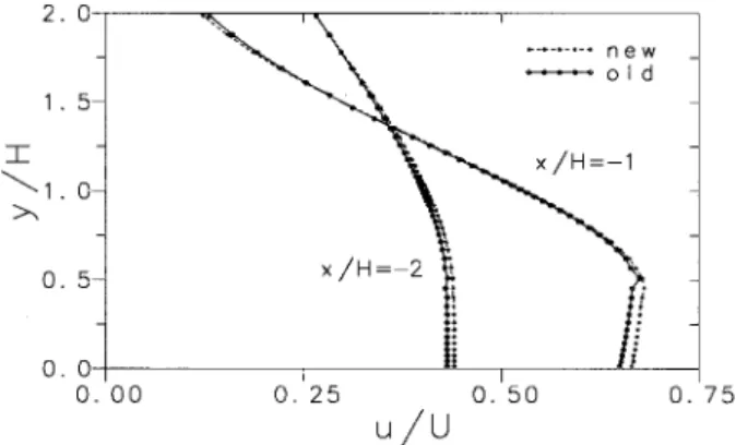
stresses do vanish, and Eqs. 15 ] 16 respect this premise. Figure 10 shows two
transve rse profile s of the longitudinal ve locity compone nt across the large channe l, at 1 H and 2 H upstre am of the contraction plane ; some localized oscillations are
visible at y
r
H f 0.5 H, where an inte rface be tween two subblocks use d to gene ratethe mesh creates a sudden nonuniform mesh-spacing change. With the pre sent formulation there are no oscillations, an indication of the be tter inte rpolation
s .
strategy achie ved with Eq. 15 .
5. CONCLUSIONS
A seque ntial segre gate d approach base d on a ge neral finite-volume method-ology in nonstagge red meshes is shown to be effective in solving the flow motion equations in conjunction with arbitrary additional constitutive equations expre ssing stress-strain relationships. The test case chosen was the typical be nchmark flow through an abrupt 4:1 planar contraction for Newtonian and viscoelastic fluids obe ying the upper-convected Maxwe ll model. A new formulation to obtain stresses at cell faces shows improve ment for nonuniform meshes, and inclusion of the div u term in the constitutive equation improve s the stability and the conve rge nce rate of the method.
Results are presente d for a range of Deborah numbe rs from 0 to 8, and for Reynolds numbe rs of 0.5 and 1.0. The streamline patte rns show the existence of corner and lip vortices at De , 1 to 4, and a vortex enhancement mechanism through lip vortex intensification followe d by finge ring of the corner vortex toward the lip, with subse que nt enve loping and merging of the two, in agre ement with the literature.
For the Newtonian mode l the results are identical to those obtaine d with a standard and well-validate d code , and the computing time is just about 18% highe r.
s .
For the UCM mode l the required computing time and number of time steps
Figu re 10. Influence of the ce ll-face stress formulation on the
solution smoothness. Tranverse profiles of the streamwise ve locity in the upstream channel at xrH s y 2 and y1, for De s 5.
tends to incre ase with the elasticity of the fluid. This was expe cted from the segre gate d nature of the method, with the stresses obtaine d from the constitutive equation being explicitly inse rted into the momentum equations, and similar de terioration of the convergence rate is found in most methods reported in the literature. Howe ve r, the present method shows good robustness, with solutions for the viscoe lastic cases achie ved for highe r De numbers than with other existing methods and where, furthermore , the time step utilize d in the computations was chosen based on the Newtonian case and was kept at a constant le vel for all runs.
REFERENC ES
1. S. V . Patankar, Num erical Heat Transfer an d Fluid Flow, Hemisphere, Washington, DC, 1980.
2. M. Peric, A Finite-Volume Method for the Prediction of Three -Dimensional Fluid FlowÂ
in Complex Ducts, Ph.D. thesis, Imperial College, University of London, 1985.
3. J. H. Ferziger and M. Peric, Com putation al Methods for Fluid Dyn am ics, Springer V erlag,Â
Berlin, 1996.
4. C. M. Rhie and W. L. Chow, A Numerical Study of the Turbulent Flow Past an Airfoil with Trailing E dge Separation, AIAA J., vol. 21, pp. 1525] 1532, 1983.
5. P. J. O liveira, F. T. Pinho, and G. A. Pinto, Numerical Simulation of Non-linear Elastic Flows with a Ge neral Collocate d Finite-V olume Me thod,J. Non-Newtonian Fluid Mech.,
vol. 78, pp. 1] 43, 1998.
6. J. M. Marchal and M. J. Crochet, A Ne w Mixe d Finite Element Method for Calculating V iscoelastic Flow, J. Non -Newtonian Fluid Mech., vol. 26, pp. 77] 114, 1987.
7. J. Y. Yoo and Y. Na, A Numerical Study of the Planar Contraction Flow of a V iscoelastic Fluid Using the SIMPLER method,J. Non-Newtonian Fluid Mech., vol. 29,
pp. 89] 106, 1991.
8. E. O. A. Carew, P. Townsend, and M. F. Webster, A Taylor-Petrov-Galerkin Algorithm for V iscoelastic Flow, J. Non-Newtonian Fluid Mech., vol. 50, pp. 253] 287, 1993. 9. T. Sato and S. M. Richardson, E xplicit Numerical Simulation of Time-De pendent
V iscoelastic Flow Problems by a Finite E lementrFinite V olume Me thod, J. Non-New-ton ian Fluid Mech., vol. 51, pp. 249] 275, 1994.
10. A. B aloch, P. Townsend, and M. F. Webster, On V ortex Deve lopment in V iscoelastic Expansion and Contraction Flows, J. Non-Newtonian Fluid Mech., vol. 65, pp. 133] 149, 1996.
11. H. Matallah, P. Townsend, and M. F. Webster, Recovery and Stress-Splitting Schemes for V iscoelastic Flows, J. Non-Newtonian Fluid Mech., vol. 75, pp. 139] 166, 1998. 12. S.-C. Xue, N. Phan-Thien, and R. I. Tanner, Three Dimensional Numerical Simulations
of V iscoelastic Flows through Planar Contractions, J. Non-Newtonian Fluid Mech., vol.
74, pp. 195] 245, 1998.
13. R. B. Bird, R. Armstrong, and O . Hassager, Dyn am ics of Polymeric Liquids, Vol. 1, Fluid Mechanics, 2d ed., Wiley, Ne w York, 1987.
14. R. B. Bird, C. F. Curtiss, R. C. Armstrong, and O. Hassager, Dyn amics of Polym eric Liquids, Vol. 2, Kinetic Theory, 2d e d., Wiley, New York, 1987.
15. R. I. Issa and P. J. Oliveira, Numerical Predictions of Phase Separation in Two-Phase Flow through T-Junctions,Compu t. Fluids, vol. 23, pp. 347] 372, 1994.
16. P. J. Oliveira, Computer Modelling of Multidimensional Multiphase Flow and Applica-tion to T-JuncApplica-tions, Ph.D. thesis, Imperial College, University of London, 1992. 17. J. P. V an Doormaal and G. D. Raithby, Enhanceme nts of the SIMPLE Me thod for
18. P. J. Oliveira and F. T. Pinho, Pressure Drop Coefficient of Laminar Newtonian Flow in Axisymmetric Sudden Expansions,Int. J. Heat Fluid Flow, vol. 18, pp. 518] 529, 1997. 19. F. Ferziger and M. Peric, Further Discussion of Numerical Errors in CFD, Int. J.
Numer. Meth . Eng., vol. 23, pp. 1263] 1274, 1996.
20. D. V . Boger and K. Walte rs, Rheological Phenom ena in Focus, Rheology Series, V ol. 4, Elsevier, Amsterdam, 1993.
21. D. V. Boger, D. U. Hur, and R. J. Binnington, Further Observations of Elastic Effe cts in Tubular E ntry Flows, J. Non-Newtonian Fluid Mech., vol. 20, pp. 31] 49, 1986.
22. L. Q uinzani, R. C. Armstrong, and R. A. Brown, Birefringence and Laser-Doppler
s .
V e locimetry LDV Studies of V iscoelastic Flow through a Planar Contraction, J. Non-Newtonian Fluid Mech., vol. 52, pp. 1] 36, 1994.