Luís Carlos da Cunha Vides Gonçalves
Underwater Acoustic Communication
System: Performance evaluation of digital
modulation techniques
Universidade do Minho
Escola de Engenharia
Luís Carlos da Cunha Vides Gonçalves
Underwater Acoustic Communication
Systems: Performance evaluation of digital
modulation techniques
Tese de Mestrado
Ciclo de Estudos Integrados Conducentes ao
Grau de Mestre em Engenharia de Comunicações
Trabalho efectuado sob a orientação de
Professor Doutor José Cabral
Mestre Marcos Martins
Universidade do Minho
Escola de Engenharia
”A sabedoria da vida n˜ao est´a em fazer aquilo de que se gosta, mas gostar daquilo que se faz.”
Acknowledgments
In first place, I would like to express my gratitude to my advisor, Professor Jos´e Manuel Tavares Vieira Cabral, for the orientation, dedication and collaboration provided during the course of this dissertation. Their expertise, understanding, and patience, added considerably to my graduate experience. I appreciate his vast knowledge and his assistance in writing this dissertation.
In second place, I would like to thank my co-advisor Marcos Martins, for the advices, the important help and all the support provided during the entire project.
I would like to thank, the Department of Industrial Electronics and Department of Phys-ics of University of Minho, all necessary conditions and facilities provided to carry out this dissertation.
A very special thanks goes out to may parents, Joaquim Gon¸calves and Rosa Gon¸calves, and sister Marcia Gon¸calves for all the unconditional support they provided me through my en-tire life and in particular, I must acknowledge my girlfriend Vˆania Fernandes, for the substantial patience and encouragement demonstrated during the good and less good times.
A word of appreciation to my unconditional friends, for their help, suggestions and ex-changes of knowledge that were indispensable and enriched my dissertation.
As it could not be left to say, I would also express my gratitude to all my University friends and colleagues for fellowship, spirit of mutual help and unquestioning support provided during my academic career.
Finally, I would like to thank all the people who contributed directly and indirectly to this project. All the people mentioned were very important during this stage and without them it would be impossible to finish my dissertation. To them I extend a considerable acknowledgment.
Abstract
This dissertation aims to describe all the research work performed to study binary digital modulations in the aquatic environment using acoustic waves. The underwater environment is considered an unreliable communication system due to countless factors affecting the propaga-tion of the acoustic waves such as: high attenuapropaga-tion at long distances, low sound speed, existence of great noise diversity, multipath and Doppler effect. These features make it extremely difficult to establish any kind of underwater communication.
Thus, initially it is necessary to perform an exhaustive survey of all the research in this area in order to understand how these characteristics may affect communication in underwater environments and subsequently identify the key concepts to future specify this type of commu-nication systems.
After that, a study about digital modulations was done in order to identify those that could be possible to conduct on this type of system. After perform an intensive research about this subject it was developed an underwater communication system using MatLab/Simulink tool with specific Xilinx blockset to verify and allow a theoretical study about the behaviour of digital modulations in underwater environment.
In order to verify the system performance and the efficiency of the performed study, a comparison between the results obtained in the theoretical system and the results obtained through practical tests was done. Through these practical tests it was possible to observe the influence of the above factors affecting the propagation of acoustic waves in underwater environments. As was initially expected, the obtained results validate and demonstrate the effectiveness of the studies that were performed.
Finally, it was still possible to identify some issues that could be addressed later, in the developing of future work in this area of research.
- Keywords
Digital modulations, Acoustic waves, Underwater environment, Attenuation, Noise, Doppler effect, Propagation delay, Underwater communication system simulation.
Resumo
Esta disserta¸c˜ao tem como objetivo descrever todo o trabalho de pesquisa realizado para estudar as modula¸c˜oes bin´arias digitais em ambientes subaqu´aticos usando ondas ac´usticas. O ambiente subaqu´atico ´e considerado um sistema de comunica¸c˜oes inst´avel, devido a in´umeros factores que afectam a propaga¸c˜ao das ondas ac´usticas tais como: alta atenua¸c˜ao em longas distˆancias, a baixa velocidade de som, a existˆencia de uma grande diversidade de ru´ıdo, o fen´omeno de multipercurso e o efeito de Doppler. Estas caracter´ısticas fazem com que seja extremamente dif´ıcil estabelecer qualquer tipo de comunica¸c˜ao subaqu´atica.
Assim, inicialmente, foi necess´ario realizar um levantamento exaustivo de todas as pesquisas nesta ´area, a fim de entender como essas caracter´ısticas podem afetar a comunica¸c˜ao em am-bientes subaqu´aticos e, posteriormente, identificar os conceitos-chave para uma futura espe-cifica¸c˜ao deste tipo de sistemas de comunica¸c˜ao.
Depois disso, foi realizado um estudo sobre modula¸c˜oes digitais a fim de identificar as candidatas a serem usadas neste tipo de sistemas. Depois de realizar uma intensa pesquisa sobre este assunto, foi desenvolvido um sistema de comunica¸c˜ao subaqu´atico usando a ferramenta MatLab/Simulink com blocos espec´ıficos Xilinx para verificar e permitir um estudo te´orico sobre o comportamento das modula¸c˜oes digitais em ambiente subaqu´atico.
De modo a verificar o desempenho do sistema e da eficiˆencia da pesquisa realizada, foi feita uma compara¸c˜ao entre os resultados obtidos no sistema te´orico e os resultados obtidos por meio de testes pr´aticos. Atrav´es destes testes pr´aticos, foi poss´ıvel observar a influˆencia dos fatores anteriormente mencionados que afetam a propaga¸c˜ao de ondas ac´usticas em ambientes subaqu´aticos. Como era inicialmente esperado, os resultados obtidos validam e demonstram a efic´acia dos estudos que foram realizados anteriormente.
Finalmente, foi ainda poss´ıvel identificar algumas quest˜oes que podem ser abordadas mais tarde, no desenvolvimento de trabalhos futuros nesta ´area de pesquisa.
- Palavras-Chave
Modula¸c˜oes digitais, Ondas ac´usticas, Ambiente subaqu´atico, Atenua¸c˜ao, Ru´ıdo, Efeito de Doppler, Atraso de propaga¸c˜ao, Simula¸c˜ao do sistema de comunica¸c˜ao subaqu´atico.
Contents
Acknowledgments vii
Abstract ix
Resumo xi
List of Figures xvii
List of Tables xxi
List of Acronyms xxiii
1 Introduction 1
1.1 Motivation and Objectives . . . 4
1.2 Application scenarios . . . 5
1.3 Dissertation structure . . . 7
2 State of the art 9 2.1 Communication systems . . . 9
2.1.1 Modulation process . . . 12
2.1.1.1 Analog modulation . . . 15
2.1.1.2 Digital modulation . . . 17
2.2 Underwater wireless communications . . . 24
2.2.1 Optical communication systems . . . 25
2.2.2 Electromagnetic communication systems . . . 28
2.2.3 Acoustic communication systems . . . 31
2.2.4 Summary of underwater communication systems . . . 34
3 Underwater acoustic channel 37 3.1 Propagation delay . . . 37
CONTENTS 3.2 Attenuation . . . 39 3.3 Ambient noise . . . 42 3.4 Doppler effect . . . 44 3.5 Multipath . . . 44 3.6 Bubbles . . . 45 4 System characterization 47 4.1 Technical decisions . . . 49 4.2 Prototype decisions . . . 50
4.3 System support overview . . . 51
4.3.1 Field-Programmable Gate Array (FPGA) . . . 52
4.3.2 Digital-to-Analog Converter (DAC) . . . 53
4.3.3 Transmitter amplifier . . . 54
4.3.4 Transducer (projector) . . . 55
4.3.5 Transducer (hydrophone) . . . 56
4.3.6 Filter and receiver amplifier . . . 56
4.3.7 Analog-to-Digital Converter (ADC) . . . 57
5 Underwater Communication System implementation 59 5.1 MatLab/Simulink . . . 60
5.2 System Generator . . . 60
5.3 Digital modulation blocks . . . 62
5.3.1 OOK modulation . . . 63
5.3.2 BASK modulation . . . 69
5.3.3 BPSK modulation . . . 71
5.3.4 BFSK modulation . . . 75
6 Tests and Results 83 6.1 Scenario 1 . . . 83 6.2 Scenario 2 . . . 84 6.3 Case studies . . . 85 6.3.1 Case study 1 . . . 85 6.3.1.1 OOK modulation . . . 85 xiv
CONTENTS 6.3.1.2 BASK modulation . . . 88 6.3.1.3 BPSK modulation . . . 89 6.3.1.4 FSK modulation . . . 89 6.3.2 Case study 2 . . . 90 6.3.2.1 OOK modulation . . . 90 6.3.2.2 BASK modulation . . . 91 6.3.2.3 BPSK modulation . . . 92 6.3.2.4 FSK modulation . . . 93
6.4 Comparison and Analysis of the obtained results . . . 94
7 Conclusions 97 7.1 Contributions and achieved results . . . 98
7.2 Future work . . . 98
List of Figures
Figure 2.1. Examples of communication systems. ...10
Figure 2.2. Communication system block diagram. ...11
Figure 2.3. Modulation Block...13
Figure 2.4. Amplitude Modulation (AM) ...15
Figure 2.5. Frequency Modulation (FM) ...16
Figure 2.6. Phase Modulation (PM) ...17
Figure 2.7. Digital comunication system ...19
Figure 2.8. Binary Phase Shift Keying (BPSK). ...20
Figure 2.9. Amplitude Shift Keying (ASK) OOK modulation...21
Figure 2.10. Binary Frequency Shift Keying (BFSK). ...22
Figure 2.11. General flow of modulations...24
Figure 2.12. Example of an underwater optical communication system [Cox07] ...25
Figure 2.13. Example applications of an Optical communication systems...26
Figure 2.14. Attenuation of electromagnetic radiation in water [Cox07]. ...27
Figure 2.15. Types of communication links in Optical Communication Systems ...28
Figure 2.16. Boat calling a submarine and a diver using electromagnetic waves...29
Figure 2.17. Propagation velocity of acoustic and EM waves in underwater environment [Rho07]...30
Figure 2.18. Example of an EM communication system ...31
Figure 2.19. First measurement of sound speed on water in 1826 [Vos10]. ...32
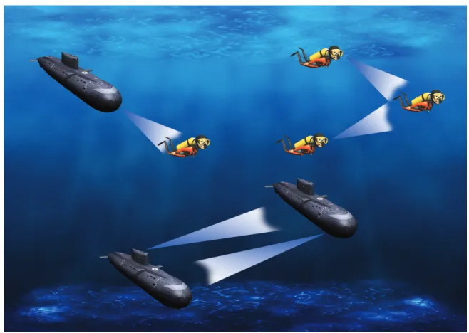
Figure 2.20. Underwater Acoustic Network [Pro12]. ...33
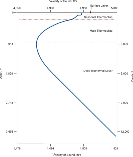
Figure 3.1. Typical sound velocity profile for the deep ocean [BS08]. ...38
Figure 3.2. Graphic of sound attenuation in water [Men11]. ...40
Figure 3.3. Narrow-band Signal-to-noise ratio (SNR) as function of frequency for dif-ferent transmission distances [SP09]. ...40
LIST OF FIGURES
Figure 3.5. Sources of noise [BS08]. ...42
Figure 3.6. Doppler effect ...44
Figure 3.7. Multipath effect ...45
Figure 4.1. Underwater communication system architecture. ...48
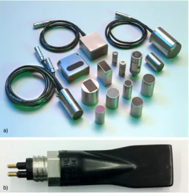
Figure 4.2. Types of existing transducers: a) Projectors b) Hydrophone ...49
Figure 4.3. Support system block diagram. ...52
Figure 4.4. FPGA used in project. ...53
Figure 4.5. DAC used in the project. ...54
Figure 4.6. Transmitter amplifier used in the project. ...55
Figure 4.7. PVDF projector used in the project. ...56
Figure 4.8. Hydrophone used in the project. ...56
Figure 4.9. Band Pass filter with gain used in the project. ...57
Figure 4.10. ADC used in the project...58
Figure 5.1. System Generator design flow. ...62
Figure 5.2. Underwater communication system block diagram...62
Figure 5.3. OOK modulator...63
Figure 5.4. Data Stream generated inside the FPGA. ...64
Figure 5.5. System Generator block...64
Figure 5.6. DAC interface. ...65
Figure 5.7. DAC Clock at 25M Hz in modulator. ...65
Figure 5.8. Result of OOK modulation. ...66
Figure 5.9. OOK demodulator. ...66
Figure 5.10. Filter construction on FDAtool. ...67
Figure 5.11. Filter specification and magnitude and phase responses. ...67
Figure 5.12. Result of OOK modulation and demodulation...68
Figure 5.13. BASK modulator. ...69
Figure 5.14. Result of BASK modulation...70
Figure 5.15. BASK demodulator. ...70
Figure 5.16. Result of BASK modulation and demodulation. ...71
Figure 5.17. BPSK modulator...72
Figure 5.18. Result of BPSK modulation. ...72
Figure 5.19. BPSK modulator with delay...73 xviii
LIST OF TABLES
Figure 5.20. Result of BPSK modulation with delay. ...74
Figure 5.21. BPSK demodulator. ...74
Figure 5.22. Result of BPSK modulation and demodulation. ...75
Figure 5.23. BFSK modulator...76
Figure 5.24. Result of BFSK modulation. ...76
Figure 5.25. BFSK demodulator solution 1. ...77
Figure 5.26. Filter construction on FDAtool to BFSK demodulation. ...78
Figure 5.27. Result of BFSK modulation and demodulation in solution 1. ...78
Figure 5.28. BFSK demodulator solution 2. ...79
Figure 5.29. Band Pass Filter constructed in FDAtool...79
Figure 5.30. Result of BFSK modulation and demodulation in solution 2. ...80
Figure 5.31. BFSK demodulator solution 3. ...81
Figure 5.32. Result of BFSK modulation and demodulation in solution 3. ...81
Figure 6.1. System architecture used in the experimental tests. ...84
Figure 6.2. Aquarium used to carry out experimental tests. ...84
Figure 6.3. Adjusting the scale values of the ADC...86
Figure 6.4. Rectification of the OOK modulated signal. ...86
Figure 6.5. Filtering process of the OOK modulated signal (low pass filter). ...87
Figure 6.6. Inverted OOK signal demodulated in FPGA. ...87
Figure 6.7. Result of demodulated OOK data stream in FPGA...88
Figure 6.8. Result of demodulated BASK data stream in FPGA. ...88
Figure 6.9. Result of demodulated BPSK data stream in FPGA. ...89
Figure 6.10. Result of demodulated FSK data stream in FPGA. ...89
Figure 6.11. Result of OOK modulation with PVDF transducer. ...90
Figure 6.12. Result of OOK demodulation with PVDF transducer. ...90
Figure 6.13. Result of BASK modulation with PVDF transducer. ...91
Figure 6.14. Result of BASK demodulation with PVDF transducer...91
Figure 6.15. Result of BPSK modulation with PVDF transducer. ...92
Figure 6.16. Result of BPSK demodulation with PVDF transducer. ...92
Figure 6.17. Result of FSK modulation with PVDF transducer...93
List of Tables
Table 1.1. Evolution of modulation techniques [APM05] ... 3 Table 2.1. Expected data rate for EM communication systems [Men11] [Rho07]. ...30 Table 2.2. Underwater Acoustic bandwidth for different ranges [APM07] [APM04]. ...34 Table 2.3. Comparison between acoustic waves, EM and optical waves in underwater
environment [LZC08]...35 Table 3.1. Sound speed variations (approximately) [BS08]. ...39
List of Acronyms
ACOM Acoustic COMmunications
ADC Analog to Digital Converter
AGC Automatic Gain Control
AM Amplitude Modulation
AMI Alternate Mark Inversion
ASK Amplitude Shift Keying
APK Amplitude Phase Keying
AUV Autonomous Underwater Vehicle
BASK Binary Amplitude Shift Keying
BFSK Binary Frequency Shift Keying
BPSK Binary Phase Shift Keying
CW Carrier Wave
CoW Continuous Wave
DAC Digital to Analog Converter
DPSK Differential Phase Shift Keying
DSP Digital Signal Processing
EM ElectroMagnetic
EMCOM ElectroMagnetic COMmunications
ELF Extremely Low Frequency
FDM Frequency Division Multiplexing
FFT Fast Fourier Transform
FM Frequency Modulation
FSK Frequency Shift Keying
FPGA Field Programmable Gate Array
HDL Hardware Description Language
ISI Inter Symbol Interference
LIST OF ACRONYMS
LEDs Light Emitting Diodes
LOS Line-Of-Sight link
MA Multiple Acess
MRL Modulating Retroreflector Link
NRZ Non Return to Zero
OCOM Optical COMmunications
OFDM Orthogonal Frequency Division Multiplexing
OOK On Off Keying
PM Phase Modulation
PLL Phase Locked Loop
PSK Phase Shift Keying
PVDF Polyvinylidene Fluoride
QAM Quadrature Amplitude Modulation
QPSK Quadrature Phase Shift Keying
RF Radio Frequency
RL Reflective Link
RTL Register Transfer Level
SNR Signal Noise Ratio
SONAR SOund Navigation and Ranging
SVP Sound Velocity Profile
TDM Time Division Multiplexing
UUV Unmanned Underwater Vehicle
1
Introduction
Along the human history, communications using sounds had played an important role in development of society, providing a means of communication between humanity. Through this, it was possible the evolution of human species up to now. So, why we do not do the same using ocean in order to acquire even more knowledge?
For several decades, electromagnetic waves, especially radio waves, had been extensively used for long range communications. However, when the propagating medium is water, elec-tromagnetic waves have a limited use, because they suffer a very significant attenuation when travel long distances. This phenomenon can be demonstrated by observing an underwater light, and trying to understand how far the light beam travels. In some areas in the world, it is impossible to see our own outstretched hands under the water, even with intense illumination [KW05].
In the fifteenth century (XV), the first document about underwater acoustics, written by the famous Leonardo da Vinci, says: ”If you stop your ship and dip one end of a long pipe in water, you will hear the noise of ships at a large distance” [KW05]. In this way, the first drafts about the underwater communications, using sound waves, began to appear. This technology had its major evolution during the 1st World War [Bor10], used as a form of sonar detection.
It became very clear in the beginning of the 20th century that sound waves could
propag-ate in wpropag-ater much more efficiently than electromagnetic waves, because they suffer less atten-uation comparatively with electromagnetic waves [KW05].
Over the times, humanity realized the importance of the oceans in our lives and through its exploitation could offer greats benefits to society.
The underwater environment, due to their particularities, can offer a wide range of inter-esting applications (some examples of these applications are provided in section 1.3). However to
Chapter - 1
develop/implement these applications it is necessary a great effort in terms of research. There-fore, and because the wireless technology is very difficult to deploy in underwater environment it is important to continue to perform many research projects in this area and thus rendering the wireless underwater communication technology a very important scientific research field.
Nowadays, underwater communication systems involve three types of transmission: elec-tromagnetic (EM), optical and acoustic [LZC08] [Men11].
Relatively to EM, it is advisable to use only in a specialized type of systems because this technique is limited by the high rate of absorption of electromagnetic signals in water [Rho07]. The second one, besides suffer the same limitation of EM have one more disadvantage: the high levels of ambient light and scattering due to the suspended particles [Arn10] [LG06]. Other disadvantage of this communication method lies in the fact that this technique is used only in a very short range (up 1 to 10 meters) [LG06]. Consequently, the implementation of these types of systems have limitations to some kinds of applications. In this way, the acoustic com-munication systems are the most versatile and largely used in underwater environments, since there is a low attenuation (signal reduction) of sound waves1 when the communication channel
is water. Today this technique is considered the most used in underwater communications, especially in deep water with a stable thermal factor. However, factors like surface ambient noise, temperature gradients and multipath propagation, due to reflection and refraction can adversely affect the use of acoustic waves in shallow water [LZC08]. In 1945, arises one of the first underwater communication system which enables the communication with submarines [Sto99].
Although acoustic communications in underwater environment has advantages compar-atively with the other techniques (optical and electromagnetic), this type of communication has some significant challenges, more specifically the much slower speed of acoustic propagation in water. Since water is a denser medium than air, the acoustic (sounds) waves can propagate faster in water than in the air. The sound speed in air is around 340 m/s, and in underwater the sound speed reach 1500 m/s. However, this value is significantly lower than the speed of EM waves, but still fast enough to provide adequate responsiveness in many applications [KW05].
Today the research in acoustic communications has increased due the variety of
applic-1”Sound waves are defined as compressional waves that have a frequency that is within the audible spectrum. Sounds outside the human hearing range are often referred to as infrasound (below 20Hz) and ultrasound (above 20kHz)”[Con08].”Sound is a form of mechanical energy, a vibration that travels as a wave by causing pressure changes in a fluid” [Bar09].
INTRODUCTION ations in underwater environment. Until the beginning of the last decade, the non-coherent Frequency Shift Keying (FSK) modulation schemes, became very favourable to exploring un-derwater acoustic communication, due the challenging characteristics offered in unun-derwater channel. This technology relies on energy detection that is a robust method for the character-istics found in underwater acoustic channel [APM05] [Hau09].
Table 1.1 shows the evolution of different modulation schemes used over the past twenty years. It is possible to observe the evolution from non-coherent modems (before 1997) to the recent coherent modems (after 1997).
Type Year Rate[kbps] Band[kHz] Range[km]a
FSK 1984 1.2 5 3s PSK 1989 500 125 0.06d FSK 1991 1.25 10 2d PSK 1993 0.3 - 0.5 0.3 - 1 200d - 90s PSK 1994 0.02 20 0.9s FSK 1997 0.6 - 2.4 5 10d - 5s DPSK 1997 20 10 1d PSK 1998 1.67 - 6.7 2 - 10 4d - 2s 16-QAM 2001 40 10 0.3s
a) subscripts d and s stand for deep and shallow water
Table 1.1: Evolution of modulation techniques [APM05]
In table 1.1 we can see that the early phase-coherent (1998) systems offer higher band-width efficiencies (bit rate/occupied bandband-width) relatively to their incoherent counterparts. However, they can not outperform incoherent modulation schemes yet. Indeed, until Inter Symbol Interference (ISI) compensation, coherent systems had lower performance than inco-herent systems for long transmissions on horizontal channels [APM05].
Although non-coherent modulation schemes, such as FSK, can be characterized by high power efficiency and their low bandwidth efficiency becomes a huge problem for high data rate sensors. In order to counteract this problem, fully coherent modulation techniques such as Phase Shift Keying (PSK) and Quadrature Amplitude Modulation (QAM) were used, due to the availability of powerful digital processing that they can provide. Thus there is an extensive research in this area [APM05] [Hau09].
Chapter - 1
Differential Phase Shift Keying modulation (DPSK) provided an intermediate solution between incoherent and fully coherent systems relatively of bandwidth efficiency. This kind of modulation can be referred as a partially coherent modulation because encodes information on the previous symbol instead to arbitrary fixed reference in the signal phase. This modulation can simplify the carrier phase-tracking requirements, but increase the error probability in PSK modulation using similar data rates [APM05].
The Orthogonal Frequency Division Multiplexing (OFDM) spread spectrum technique became a promising solution for underwater communications. This technique consist in a Frequency Division Multiplexing (FDM) scheme that use a digital multi carrier modulation method. To transmit data, a set of independent orthogonal sub carriers are used and the total bandwidth is divided into a large number of narrowband channels. Each channel does not interfere with the others [Pal09].
In order to offer bandwidth more efficiently in underwater acoustic channels the spread spectrum techniques emerged. With OFDM we can transmit more data in the same amount of time by using a larger amount of bandwidth. Other advantage is that OFDM can easily adapt to the severe features found in the underwater channel without the need of complex equalization. This system is robust against narrow band co-channel interference and against ISI. Underwater communication systems poses significant challenges in wireless transmission and OFDM is equipped to handling with these problems, such as multipath transmission [KT08].
Thus, any underwater communication system depends on the characteristics of the envir-onment. Oceans are so complex and dynamic that makes difficult to predict the behaviour of the system. So, in addiction to everything mentioned above it is necessary to require a detailed knowledge of all physical factors in underwater environment to consequently choose the wireless technology and the associated modulation techniques.
Construct a reliable system that works perfectly in a huge range of distinct environments remains a challenge [Pre06].
1.1
Motivation and Objectives
Why study acoustic underwater communications? What is the motivation to read this dissertation?
Throughout the human history, the communications have an important role in the inter-action among people and to the development of society.
Oceans cover 70% of the earth surface and most of this part remains unexplored when 4
INTRODUCTION compared with land areas [Men11]. So, why not study the oceans in order to acquire more knowledge? Through underwater communication systems can be explored the many mysteries that remain hidden in the oceans highlighting aspects that otherwise might never be discovered. For the correct and efficient use of these kind of communication systems, it is necessary to understand the acoustic waves and water properties. After that we need to trace certain goals to build the communication model and identify all important aspects that are feasible within the available time.
So, the main goals of this dissertation are:
• Study and identify the important aspects required to develop an underwater communication simulation model;
• Study various modulations techniques, in order to identify those that offer better performance;
• Simulate an underwater communication channel (e.g.MatLab/Simulink/Xilinx), to make possible the development of an underwater communication system; • Develop an acoustic underwater communication system using digital
modula-tions using a FPGA (field programmable gate array) based platform; • Perform some experimental tests to validate what was previously studied.
1.2
Application scenarios
Wireless transmission through the oceans is one technology that allows the development of future observing systems of aquatic environment, serving as support for the oil industry, providing monitoring tools to study and research the marine life.
Currently, applications for underwater communications are explored in military, com-mercial and academical areas, making there use even more wide and diverse.
Some of these applications, that can use wireless transmission, through the oceans, are: [Men11],[APM05]
1. Environmental monitoring
• Pollution (chemical, biological and nuclear); • Monitoring of ocean currents and winds; • Improved weather forecast;
Chapter - 1
• Climate change;
• Predicting the effect of human activities on marine ecosystems; • Ocean salinity and PH control.
2. Underwater explorations • Explore marine life;
• Detecting underwater oilfields or reservoirs; • Assist in exploration for valuable minerals. 3. Disaster prevention
• Measure seismic activity to avoid tsunamis; • Study the effects of submarine earthquakes; 4. Assisted navigation
• Identify hazards on the seabed (dangerous rocks, submerged wrecks and shoals in shallow waters);
5. Rescue missions
• Provide help in shipwrecks; 6. Information collection
• Ocean mapping; • Study of marine life; 7. Surveillance systems
• Mine reconnaissance;
• Intrusion detection systems; 8. Underwater communications
• Diver communication (diver to diver or diver to ship);
• Underwater Internet through Underwater Sensor Nodes (USNs); 9. Assisted or Autonomous navigation
• Unmanned Underwater Vehicles (UUVs); • Autonomous Underwater Vehicles (AUVs); 6
INTRODUCTION
1.3
Dissertation structure
This document describes all the research developed to specify and develop a system to evaluate the performance of several modulations schemes in underwater acoustic environment. This document is divided in 7 chapters.
After the introduction, chapter 2 and 3, presents the main themes surrounding the subject of this dissertation. Themes like, communication systems, modulation process, underwater wireless communications, acoustic propagation properties in water were taken into account.
The general description of the aspects presented in this work were discussed in chapter 4. The support system used to perform the work was briefly described and all the decisions considered important to the realization of the project were addressed. It was conducted a brief description about some concepts presented in system components, that can indicate the best selection to perform the proposed project.
In the chapter 5 it is presented the simulation of the modulation schemes, discussed in chapter 4. These simulations are performed in order to understand the one that best fits in un-derwater environment. During this chapter, all modulations blocks were thoroughly described. In the chapter 6 were described all tests performed to study modulation schemes beha-viour in underwater environment. The scenario and the environment conditions were extremely important and consequently were taken into account and were covered in this chapter. It was also carried out a comparison between the results obtained in experimental tests and the results obtained through simulation, submitted in chapter 5.
Finally, chapter 7 presents the conclusions of this dissertation. This chapter include some possible modifications in modulation schemes to improve the underwater communication system (e.g. speed, efficiency) and provide some ideas to take into account in future work.
2
State of the art
Before starting any implementation, it will be necessary to perform theoretical analysis on the technologies surrounding, as well as the requirements that the system is subject. In this way, this chapter is intended to gather the basic concepts presented along this dissertation.
Initially it will be presented some important concepts about communication systems, with the intention to explain how they work. Along this chapter, subjects like modulation, demodulation will be discussed in order to provide a further insight into the communication systems.
Then, it will be presented the three types of wireless underwater communication known until now, and the advantages and disadvantages of each one and their applications.
2.1
Communication systems
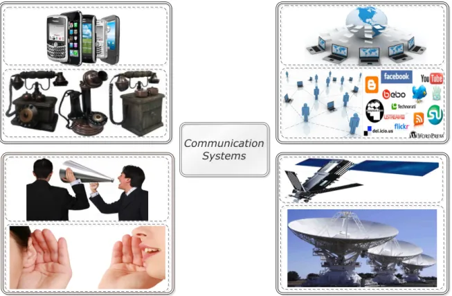
Nowadays, many communication systems are present in quotidian and in such a diversified way. Telephones at our hands, radios in our living rooms, computers with access to internet in our office, TV channels transmitted through satellite and even our speech (see figure 2.1), are examples of a communication in the present days [Hay01].
A communication system can be defined as a medium (transmission channel), through which information flows (are transmitted) from a given location (emitter) to another location (receiver) [Men11].
Chapter - 2
Communication Systems
Figure 2.1: Examples of communication systems.
Along this transmission a sequence of specific processes are established, that are described below [Hay01], [Men11].
1. Conception of a message signal;
2. Description of that message signal, through a set of symbols, performed with some precision;
3. Coding of these symbols, with the most appropriate way according to the physical transmission medium;
4. Transmission of encoded symbols to its destination; 5. Decoding and reproduction of the original symbols;
6. Recreation of the original signal, with a deterioration (e.g. noise, interferences) in their quality according to the imperfections of the system;
Regardless of the communication process that we want to analyse, there are always three basic elements in each communication system.
These basic elements are the emitter, that has the purpose of converting the original signal that was produced by the source of information, in a suitable ”format” for its propagation 10
STATE OF THE ART through the medium (channel); the transmission channel, where the signal will be transmitted and, finally, the receiver that has the task of recovering, in a ”recognizable” format the original signal from the received signal to be interpreted by the target user.
The transmission channel consists in the electrical medium that bridges the distance from the source of information to the destination. It may be constituted by a par of wires, a coaxial cable, radio wave or a laser beam. This channel will be constructed according with the needs of the system. Every channel introduces some amount of transmission loss or attenuation and this way we can say that the signal power will be progressively decreased with the increasing distance. [Car86].
As previously stated, the receiver operates on the output signal and has the function to reconstruct the original signal and deliver it to destination (user of information). Receiver oper-ations includes amplification, to compensate for transmission loss, demodulation and decoding to reverse the signal processing performed initially at the emitter [Car86].
It should be noted that, besides the distortion undergone by the signal in its propagation over the transmission channel, the signal will be further modified due to factors such as noise and interfering signals, originated in other sources, which are added to the output of the transmission channel. With this, we can say that the received signal are a corrupted version of the transmitted signal [Hay01], [Men11].
This can be observed in the block diagram of a generic communication system presented in the figure 2.2.
Transmission Channel Source of
information Message Transmitter Receiver informationUser of
signal Estimate of message
signal
Transmitted
signal Received signal
Communication System
Noise interferences and distortion
Chapter - 2
When we want analyse a communication system, we must always keep in mind some important aspects, namely:
• The kind of information that will be transmitted; • How we should transmit these information;
• At which instant of time these information should be transmitted; • Where is the destination of information that we are sending; • From where is the information that we are expecting to receive.
As stated above, there are many kinds of communication systems. We can identify two major groups, namely wired communication systems and wireless communication systems.
Wired communication systems are constituted by: coaxial cable, telephone cable, optical fiber, among others. On the other hand, the wireless communication systems consists of com-munications such as: acoustic waves, optical signals, electromagnetic waves, satellite and laser beam [Men11].
In this way, the choice of communication systems types to use will be dependent on the criteria aforementioned to make the system more robust and effective as possible.
Like in every systems, we can face some limitations when designing communication sys-tems. The fundamental limitations can be divided in two general kinds of constrains. One kind are the technological problems, including some considerations like hardware availability, economics factors, federal regulations and so on.
On the other hand we have the fundamental physical limitations, namely the laws of nature. These limitations, ultimately dictate what can or cannot be done, irrespective of technological problems that can exist. The fundamental limitations of information transmission by electrical means are bandwidth and noise [Car86].
2.1.1
Modulation process
As well known, signals cannot be sent directly through the transmission channels. This occurs due to its shape. This way, before the transmission, every signal suffer a process called modulation [Men11].
Limitations of the transmission channel can be overcome with the reduction of the effects of noise and interference.
Modulation is the process of varying one or more parameters of a periodic waveform, called the carrier signal, of a function of a modulating signal which contains the information 12
STATE OF THE ART that we want to transmit (original signal). On the other hand, the receiver recreate the original signal from a degraded version of a transmitted signal after its propagation by the transmission channel. The process behind the recreation of the original signal is called demodulation [Hay01]. In this way, the modulation is the process of superimposing a message signal, to a carrier signal, resulting in a modulated signal. This process can be observed in figure 2.3.
! ! ! ! ! ! ! ! ! ! ! ! ! ! ! ! Carrier! Input!Signal! Modulated!Signal! Modulation!Block!
Figure 2.3: Modulation Block.
When we use a carrier wave, we can obtain properties of the signal, which are more advantageous to the transmission channels. One example of the modulation process can be observed when humans speak. The voice is transmitted through the air that, due to the high-frequency carriers present in vocal cords, are modulated by the muscular action of the oral cavity leading to the formation of the modulated signal. This way, our ears are one type of demodulator that interpret the voice like modulated acoustic waves [Men11],[Car86].
As previously stated, the process that reverse the modulation is called demodulation. However, the presence of noise and distortion in the received signal (modulated signal) is unavoidable, and makes it practically impossible to recreate exactly the original signal [Hay01]. In this way, we can conclude that the choice of modulation type is an extremely important aspect in the specification of the transmission link, because this choice affects the performance of the communication system.
We know that, some modulation schemes are less sensitive to the effects of noise and distortion than others and, due to this fact, it is necessary to analyse, in detail, the specifications and requirements of the communication system to subsequently choose the best modulation process.
The primary purpose of using modulation in a communication system is to generate a modulated signal suited to the transmission channel. Nowadays, exist several practical benefits and applications when we use modulation process, which will be briefly discussed below [Car86].
Chapter - 2
• Modulation for efficient transmission
Signal transmission over a certain distance, always involves a travelling elec-tromagnetic wave and, its efficiency depends upon the frequency of the signal being transmitted. In this way, using properties of translation frequency of car-rier wave (CW) modulation, the information can be combined with a carcar-rier, whose frequency was selected for desired transmission method.
• Modulation to overcome hardware limitations
The construction of a communication system can be constrained by the high cost and availability of hardware, whose performance depends most of the times upon the frequencies involved. So, modulation process allows the designer to put the signal in some certain frequency range, and this way avoid hardware limitations.
• Modulation to reduce noise and interference
To combat noise and interference a brute-force method is used that consists in increasing the signal power until it overwhelms the contaminations. However, increasing signal power is expensive and can be damage the equipment. Fortu-nately, some types of modulation have the valuable property, called wideband noise reduction, that suppresses the noise and interference.
• Modulation for frequency assignment
When we tune a radio or a TV set to a determined station, we are selecting one of many signals being received at that time. Every stations have different assigned carrier frequency, so the desired signal can be separated from the other by filtering.
• Modulation for multiplexing
Multiplexing consists in combination of several signals for simultaneous trans-mission on one channel. Techniques like Frequency Division Multiplexing (FDM) uses continuous wave (CoW) modulation to put every signal on a distinct car-rier frequency, and uses a bank of filters to separates the signals at the destina-tion. Time Division Multiplexing (TDM) uses pulse modulation to put samples of distinct signal in non overlapping time slots. A variation of multiplexing is called multiple access (MA). While multiplexing involves a fixed assignment of the common communication resource, at the local level, MA involves the remote sharing of the resource.
STATE OF THE ART In short, we can identify two basic modulation types: Analog and digital modulation.
2.1.1.1 Analog modulation
Analog modulation, also known as continuous wave (CoW) modulation, use a sinusoidal wave as the carrier and, the signal that we want transmit is analog or continuous. It should be noted that in analog modulation, the parameter that is being modulated, varies in direct proportion to the sign that we intend to transmit.
In this kind of modulation, the carrier will have a much higher frequency than any frequency components, which are contained in the signal to be modulated [Men11].
The modulation process consist in the displacement of the frequency spectrum of the message that we want transmit (original message) to a new and higher frequency band.
The modulation techniques most used in analog signals are the Amplitude Modulation (AM) and angle modulation, whereas the last mentioned can be divided in Frequency Modulation (FM) and Phase Modulation (PM).
Amplitude Modulation:
AM, consist in variation of the amplitude of the carrier in accordance with the amplitude of the original message that we want transmit [Hay01].
This can be observed in the figure 2.4.
Chapter - 2
Angle Modulation:
As previously mentioned, angle modulation is an analog modulation technique. This technique consist in the variation/modification of the angle of the carrier.
However, this modulation can be further subdivided in FM and PM, which can be char-acterized with the variation of the frequency and phase respectively in accordance with the message signal [Hay01].
Frequency Modulation:
FM can be characterized with the variation of the frequency of the carrier in accordance with the amplitude of the message signal. The frequency carrier will change based on the amplitude of the signal that we intend to transmit (the carrier frequency varies linearly with the amplitude of this signal), and which varies with time, while the carrier amplitude is unchanged (fixed). This can be observe in the figure 2.5.
The greater the amplitude of the message signal, greater will be the frequency produced.
Figure 2.5: Frequency Modulation (FM)
Phase Modulation:
In PM, the phase of the carrier signal will be directly modified by the signal that we intend to transmit, that is, in PM the carrier phase varies according with the amplitude of the signal that we want to transmit.
STATE OF THE ART As we can see in figure 2.6, the angle of the carrier wave changes consonant the charac-teristics of the signal that we want to transmit.
Figure 2.6: Phase Modulation (PM)
2.1.1.2 Digital modulation
The transmission of data through a digital communication system can be made through two different methods: base band or channel band. In the first case, the data is encoded through the code line NRZ (Non-Return-to-Zero), AMI (Alternate Mark Inversion), Manchester or 2B1Q and sent through the transmission channel. In the channel band data undergo a process called modulation that shifts the spectrum of the baseband signal and focuses it on a given frequency. Thus it is possible, unlike base band, send data from several different sources simultaneously, achieving a multiplexing technique. Another reason why it uses modulation, is the frequency behaviour of the transmission channel, which is not constant along the spectrum [dOF11].
In a digital communication system, digital modulation is used, also known as coded or discrete modulation, that consists in the modulation of an analog carrier signal by a discrete signal [Men11]. This modulation allows transforming digital signals in waveforms to be trans-mitted in the communication channel. This technique is characterized by the transmission and detection of a particular wave, through one finite set of waveforms that are known.
There are two broad categories of digital modulations: pulse modulation and keying modulation, which subsequently are divided into many other modulation techniques.
Chapter - 2
When we talk about a digital system, we find the following question: ”What advantages we can have with digital system over analog ones?” This is an obvious question because, after all, an analog system requires only few components to be implemented, whereas to make an digital system it is necessary significantly more hardware.
Nonetheless, despite the increasing of hardware intricacy, we gain some advantages, namely [Car86]:
1. Stability
Every digital system are inherent time invariant. To make greater accuracy in signal reproduction, are incorporated key systems parameters in algorithms, that only change if are reprogrammed. So, when is used analog hardware, its signal and its parameters can be subject to change with component ageing, external temperatures and other environmental factors.
2. Flexibility
Once a digital system is finished, we have a great flexibility in changing the system. In this way, it is possible to employ a multitude of signal processing algorithms more efficiently:
(a) Ameliorate signal fidelity;
(b) Make error correction/detection for data precision; (c) Prosecute encryption for privacy and security of data; (d) Perform compression algorithms to remove redundancies;
(e) Enable to do multiplexing of several types of signals (voice, pictures, video).
Furthermore, these algorithms can be easily and remotely modified if it is necessary.
3. Reliable Reproduction
As previously referred, an analog message, travelling through a channel, be-comes degraded with the action of distortion and noise presented in every transmission channel. To solve this problem, we can add amplifiers to increase the signal power. However this amplification increases the noise also and, can only increases distortion. This way, the distortion becomes cumulative. One example of this phenomenon can be observed when we make a photocopy of another photocopy.
STATE OF THE ART In short, when compared with the analog modulation, digital modulation provides a greater ability to transmit large amounts of information, gives a greater compatibility with the digital data services, enhances the security of the data that will be transmitted and provides a better quality of communication.
In the figure 2.7 we can observe a generic digital communication system.
Figure 2.7: Digital comunication system
Pulse modulation consists in a method that ”treats” (represents) the information as a sequence of pulses (pulse train), in which one or more characteristics of each pulse are modified in accordance with the variation of the input signal.
As previously mentioned, keying modulation are one category of digital modulation where the signal to be transmitted has a limited number of states to represent digital states that correspond to it (usually used zero or one). We can say, in a generic and simplistic way, that this type of modulation is a way to convert a digital signal in an analog signal.
The purpose of this type of modulation is allow the transmission of a digital signal through an analog communication channel. This type of modulation also have numerous techniques, which some of them will be now addressed.
Phase Shift Keying (PSK):
The PSK modulation technique consists in transmit data by changing or modulating the phase of a reference signal, which is called CW. This technique uses a finite number of phases, in which each phase assumes a unique pattern of bits. Thus, each pattern forms a symbol which are represented by the phase in question (particular phase).
Phase, in this particular context, is the starting angle at which the sinusoid begins. Depending on the start of the binary sequence, to transmit the binary symbols 0 or 1, we shift the phase of the sinusoid by 180 degrees. This modulation method is called Binary Phase Shift Keying (BPSK) (see equation 2.1).
Chapter - 2 BP SK(t) = Asin(2πf t) if bit =0 Asin(2πf t + π) if bit =1 (2.1) In the other hand, the receiver will make the determination of its phase and mapping back to the symbol it represents, to thereby retrieve the original data.
The most simplistic modulation in PSK is the BPSK, where the pair of two signals are used to represent binary symbols 1 and 0.
The result of this modulation can be observed in the figure 2.8.
Figure 2.8: Binary Phase Shift Keying (BPSK).
As seen in figure 2.8, a pair of sinusoidal waves are used and only differ in a relative phase shift of 180 degrees, to represent binary symbols 1 and 0. However, it is possible to encode more than one bit, giving rise to multi-symbols modulations, such as Quadrature Phase Shift Keying (QPSK).
Amplitude Shift Keying (ASK):
ASK modulation is the change of the level of the amplitude of the carrier wave in ac-cordance with the signal that we want transmit. So, to represent the binary symbol 1, is transmitted a signal with a particular amplitude and, to represent the binary symbol 0, we change the amplitude keeping the frequency constant (equantion 2.2).
BASK(t) = A1sin(2πf t + θ) if bit =0 A2sin(2πf t + θ) if bit =1 (2.2) 20
STATE OF THE ART Its operating principle can be explained through two of their particular types of modu-lations, the Binary Amplitude Shift Keying (BASK) and On - Off Keying (OOK).
In BASK modulation, presented in equation above, the signal that we want modulate will assume one of two possible discrete levels of the existing source of information (logic level 0 or 1). Typically, on the BASK modulation, the smaller amplitude corresponds to the logical level 0 and the largest amplitude corresponds to the logical level 1. In the other hand, the OOK modulation, the carrier assumes a certain level of voltage to the logic level 1 and zero voltage to logic level 0. Therefore, the magnitude of the modulation index is unitary [GTL06].
In the figure 2.9 we can observe the result of OOK modulation.
Figure 2.9: Amplitude Shift Keying (ASK) OOK modulation.
Like in other modulations, using multi-symbols is possible to increase the speed of com-munications, encoding this way more than one bit simultaneously. Thus, it can be used mod-ulations like, for example, 4-ASK and 8-ASK.
Frequency Shift Keying (FSK):
FSK modulation technique consists in discrete variations in frequency of the carrier wave in accordance with the signal we want to modulate. The frequency to be transmitted will be the result of the carrier frequency plus the offset for that undergoes one of the points.
In the Binary Frequency Shift Keying (BFSK) modulation, symbols 1 and 0 are dis-tinguished from each other, through transmitting one of two sinusoidal waves that differ in frequency by a fixed amount [Hay01]. This can be observed in equation 2.3.
BF SK(t) = Asin(2πf1t + θ) if bit =0 Asin(2πf2t + θ) if bit =1 (2.3)
Chapter - 2
The FSK modulator is formed by two ASK modulators, one of which produces modulated pulses in the frequency F1 for each bit 1, while the other produces modulated pulses in the
frequency F0 for each bit 0. The output of the modulator is combined and transmitted [GTL06].
The result of this modulation can be observe in the figure 2.10.
Figure 2.10: Binary Frequency Shift Keying (BFSK).
Digital modulation can be classified into coherent and non-coherent techniques, depend-ing if the receiver is equipped with a phase recovery circuit or not. This circuit ensures that the oscillator supplying the locally generator carrier wave in the receiver is synchronized (in frequency and phase) to the oscillator supplying the CW used to modulate the incoming data stream in the emitter [Hay01].
Differently to ASK signals, PSK and FSK signals have constant envelop. Because of this property PSK and FSK signals are impervious to amplitude non-linearities, commonly encountered in micro-waves radio and satellite. In practice, through this reason, we find that PSK and FSK signals are preferred to ASK signals for passband data transmission over non-linear channels [Hay01].
All modulations described above, are called binary modulations because bits 0 and 1 are modulated in sinusoidal pulse sequences with amplitude, frequency or phase variables associated to the bit stream. However, this type of modulation is not effective when aiming at high speeds, where it is necessary to encode more than one bit simultaneously.
M-ary modulation is able to encode more than one bit simultaneously and, this way, it can be used when high speeds are necessary. In M-ary signalling scheme, we can send one of M possibles signals S1 (t ), S2 (t ),...,SM (t ) , during each signalling interval of duration T.
In this modulation k bits are encoded that will give rise to different M symbols, where k is an integer [Car86],[Hay01].
STATE OF THE ART This can be observe in the equation 2.4.
M = 2k (Sym) (2.4)
In turn, each symbol is represented by a sinusoidal pulse with a duration corresponding to the respective symbol. In this way it is possible to define the value of the symbol time (Ts), depending on the bit time (Tb). The equation that makes possible defining this value can be observed in 2.5 [Car86], [Hay01].
Ts= Tb× k (Sym/s) (2.5)
Finally, the transmission frequency or binary rhythm Rb, is given by equation 2.6, where
the transmitted symbols rate Rs is called baud rate and is represented by [symbols/s] [Car86].
Rb = Rs× log2(M ) = Rs× k (Bits/s) (2.6)
In passband data transmission the signals are generated by changing the phase, frequency or amplitude of the sinusoidal carrier in M discrete steps. So, we have M-ary PSK, M-ary FSK and M-ary ASK digital modulation schemes.
So, we can conclude that all modulations mentioned above, can modulate more than one bit, giving rise to modulations such, for example, 4-ASK, 4-PSK, and 4-FSK.
However, with the combination of different methods of modulations into a hybrid form, we can get another way to generate M-ary signals. We can combine, for example, discrete changes in both the amplitude and phase of a carrier to produce modulation such M-ary Amplitude Phase Keying (APK).
One special kind of this hybrid modulation is the M-ary Quadrature Amplitude Modu-lation (QAM), which has some attractive properties. It transmits two digital bit streams, by modulating the amplitudes of two carrier waves, using the ASK modulation scheme where the two carrier waves, are out of phase with each other by 90 degrees. The modulated waves are summed, and the resulting waveform is a combination of both PSK and ASK modulation. We can say that M-ary ASK is a special case of M-ary QAM modulation [Hay01].
One important aspect is that binary signalling provides the greatest immunity to noise for a given S/N because it has only two amplitude levels and we cannot send information with less than two levels. On the other hand, multilevel M-ary signalling requires more signal power but requires less transmission bandwidth. This happens because signalling rate will be smaller than bit rate of an equivalent binary signal. Therefore M-ary signalling can be used in
Chapter - 2
applications such as digital transmission over voice channels, where the available bandwidth is limited and the signal-to-noise ratio is relative high [Car86].
Nowadays, M-ary modulation are often used in the construction of robust systems re-quiring high speeds.
Finally, in figure 2.11 we can be observe the graphic flow of modulations, where the various types of modulations are grouped, taking into account their characteristics.
Modulations Techniques
Digital Modulations
DSB SSB VSB FM PM
Amplitude Modulation Angle Modulation
Analog Modulations DSB-WC DSB-SC DSB-RC Pulse Modulations Analog/Digital PCM PFM DM PAM PWM PPM Analog/Analog DPCM ADPCM SDM ADM Keying Modulations
PSK CAP FSK QAM ASK TCM DMT CPM OFDM BPSK QPSK DPSK DQPSK OQPSK MSK GMSK BFSK AFSK MFSK DMTF GFSK CPFSK BASK OOK MASK
Figure 2.11: General flow of modulations
Until now, the important topics about communication systems were presented to provide the necessary background to the reader of this dissertation understand the next topics that will be presented. In the next section it will be presented, in detail, the characteristics of the underwater communication systems.
2.2
Underwater wireless communications
Today, wireless communication technology is presented in our lives in so many ways that it is almost indispensable for the functioning of quotidian life. However, despite the oceans cover 70% of the earth surface [Men11], underwater wireless communication continues unexplored when compared with the others wireless communications technologies. Currently, there has been an increase on the interest in the development of wireless communication systems in underwater environment. This increase has lead to intensive research on methods that allow 24
STATE OF THE ART this kind of transmission of information.
The result of this research may be organized in three big systems: Optical COMmunic-ations (OCOM), communicCOMmunic-ations using ElectroMagnetic (EM) waves and Acoustic COMmu-nications (ACOM).
2.2.1
Optical communication systems
Underwater OCOM systems arises with the emerging need to provide a high-speed com-munication in some applications that require a real time high-data-rate comcom-munication [Arn10]. This technology is a potential solution for high bandwidth and low latency in underwater wire-less communications [CSD+08].
One example of underwater OCOM systems can be observed in figure 2.12 where an Unmanned Underwater Vehicle (UUV) or an Autonomous Underwater Vehicle (AUV) commu-nicates with the underwater receiver using optical technology.
2
As the amount of undersea exploration and exploitation of undersea resources increases, aquatic freespace optical communication links are potentially very useful in several situations, including:
Underwater observatories
Underwater vehicle to surface ship links
UAV to moored or floating Buoys equipped with RF links. AUV to AUV communications
Diver to diver or diver to ship communications.
Underwater observatories like in [2] are stationary installations that monitor interesting seafloor features like hydrothermal vents or coral reefs. Such installations may be permanently fixed to the seafloor and passively collect data over time. Once the local storage space has been filled, or when data is needed by scientists, a small AUV or surface ship could communicate with the observatory via an optical link to extract its data.
Figure 1-2 – AUV communicating to underwater observatory via optical modem [2] Figure 2.12: Example of an underwater optical communication system [Cox07]
This technology consists in underwater observatories that monitor some interesting re-sources on the seabed. These installations can be permanently fixed to the sea floor, collecting data over time. To collect the data an AUV that communicate with the observatory via an optical link is used. This kind of system is useful to various scenarios, namely can be employed for military uses to locate and disarming underwater mines or for finding enemy submarines
Chapter - 2
[Cox07]. Figure 2.13 shows several examples where underwater optical communication links are very useful.
Figure 2.13: Example applications of an Optical communication systems
Using optical communications we can improve some kinds of communications (diver-to-diver and diver-to-ship). Some activities like diving becomes dangerous due to the lack of communication with other dive partners or with the surface. With an optical link it is possible to improve underwater communications, providing transfer of data, such as navigation information between divers [Cox07].
In short, the underwater OCOM systems consists in a small group of components, where the transmitter converts received information in an optical signal and send it through the transmission medium (water). In the other hand, the receiver detects the optical signal and converts it back into an electrical signal which, subsequently, is sent to the data destination [Men11].
The OCOM systems become quite popular in the last years with the creation of reliable, low-cost light sources, such Light Emitting Diodes (LEDs) and Laser Diodes (LDs), that take advantage of the comparatively low attenuation of light in the 400nm - 550nm range in seawater [CSD+08]. There are several types of light sources but, because of the environment in which they are placed and their characteristics, the choice falls between the two types mentioned 26
STATE OF THE ART above. Like in other systems, both the LEDs and LDs technologies have some advantages and disadvantages which makes difficult to choose the technology to use [Bru10]. After identified the appropriate technology (source of light) for the proposed system it is necessary to take into account the choice of light color.
In figure 2.14 we can observe the attenuation of electromagnetic radiation and we can concluded that blue/green wavelength are the best option for underwater environments [Cox07].
Figure 2.14: Attenuation of electromagnetic radiation in water [Cox07].
Underwater OCOM system has three types of communication links: Line-Of-Sight link (LOS), Modulating Retroreflector Link (MRL) and Reflective Link (RL) [Arn10].
LOS is the most common model communication link, where a connection between two points in wireless OCOM system is required (figure 2.15 A). In this scenario the transmitter (Submarine) directs the light beam in the direction of the receiver (diver). In this kind of technology the transmitter must be located in the line of sight of the receiver [Arn10].
MRL is an optical model used when one part of the transmission (for example the sub-marine) system has more resources than the other (diver). In the figure 2.15 B it is possible to observe that the submarine (interrogator) has more energy, while a small modulating op-tical retro reflector is installed on the remote end (diver). The submarine illuminates the retro reflector of diver with a beam of continuous waves. On the other hand, the diver reflects this beam back to the submarine while modulates the information on it [Arn10].
Chapter - 2
obstructions or misalignment of the transceivers. This way, the RL can be used. Thus, the transmitter emits a beam of light toward the surface. When the beam reaches the water-air surface is partially reflected to the receiver (see figure 2.15 C) [Arn10].
Figure 2.15: Types of communication links in Optical Communication Systems
2.2.2
Electromagnetic communication systems
Wireless communication systems that use EM waves, in particular Radio Frequency (RF) systems, are very used today. However, this kind of technology becomes very limited in aquatic environment because of the factors inherent to this medium, especially in the case of sea water [Lov06] [She05].
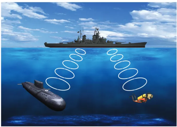
In figure 2.16, it is possible to observe the only underwater application successfully im-plemented that use EM waves technology. This application is Extremely Low Frequency (ELF) and consists in a bell that calls a submarine or a diver to the surface [Rho07]. This system is not very efficient because do not allow the realization of a data exchange between the entities; it only allows to call the receiver of information (submarine or diver for example) to the surface. Once on the surface, the entities will communicate using terrestrial radio to data exchange. 28
STATE OF THE ART One of the pioneer, in radio communications to submarines underwater was Germany during World War II with the construction of ”Goliath” in 1941 [She05].
Figure 2.16: Boat calling a submarine and a diver using electromagnetic waves
EM propagation through water is very different from the propagation through the air. This difference can be explained by high permittivity and electrical conductivity. When com-pared with the air, the plane wave attenuation is high and increases rapidly with frequency. The water is the material that have one of the highest permittivity and causes significant impact on the refraction angle at the air/water interface [Rho06]. Due to these properties, an EM signal has a different propagation in seawater or freshwater.
Figure 2.17 shows the effect of increasing frequency in propagation velocity of EM waves for sea water, freshwater and free space, comparatively to the acoustic propagation velocity. It is possible to observe the increase of propagation velocity with the augmentation of frequency and its difference of propagation between seawater and freshwater.
Chapter - 2
SEAS DTC Technical Conference - Edinburgh 2007
3
Another important consideration is the
effect of the air to water interface.
Propagation losses and the refraction angle
are such that an electromagnetic signal
crosses the air to water boundary and
appears to radiate from a patch of water
directly above the transmitter. The large
refraction angle produced by the high
permittivity launches a signal almost
parallel with the water surface. This effect
aids communication from a submerged
station to land and between shallow
submerged stations without the need for
surface repeater buoys.
Figure 3 shows attenuation through the
water path but for communication between
shallow submerged stations most of the
signal is carried by the air path and this
plot should not be interpreted using
horizontal range. For example if two
divers are 1 km apart , 2 m below the
surface attenuation will be significantly
less than anticipated from the 1 km
through water loss. In comparison
acoustic signals cannot cross the water to
air boundary so 1 km through water loss
would apply.
A similar effect is seen at the sea bed
where conductivity is much lower than the
water. The sea bed is an alternative low
loss, low noise, covert communications
path. Figure 4 illustrates the propagation
paths
that
can
be
exploited
for
communications. In many deployments a
single propagation path will be dominant.
Submarine ELF systems use line antennas
trailed by the vessel while submerged but
this system only implements receive at the
submerged node. Magnetic coupled loop
antennas are most compact practical
solution for duplex submerged systems.
Loop antennas are directional in nature and
this property can be exploited to allow
selection of a single propagation path.
Alternatively omni-directional antennas
can be implemented by crossing two loops
so their planes intersect at right angles.
Larger loop area will always give greater
antenna gain but practical systems can be
designed using relatively compact loops.
For example, WFS has built demonstrator
systems based around a 0.5 m loop
diameter.
Figure 1 EM prop velocity in water
Figure 2 EM wavelength in water
Figure 3 EM propagation distance for 100
dB attenuation through water.
Note for communication between shallow
submerged stations most of the signal is
Figure 2.17: Propagation velocity of acoustic and EM waves in underwater environment [Rho07].
In Table 2.1, it is possible to observe the propagation of EM signal in seawater and freshwater. This table shows the relation of distances and bit rates for systems using EM waves [Rho07] [Men11].
Range <1m 10m 50m 200m 2km 10km
RF in seawater Up to 100Mbps 100Kbps 5Kbps 100bps 10bps 1bps
RF in freshwater Up to 100Mbps 1Mbps 100Kbps 1Kbps 10bps 1bps
Table 2.1: Expected data rate for EM communication systems [Men11] [Rho07].
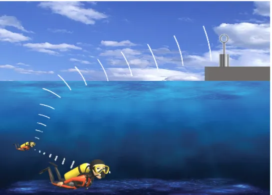
One important fact, when we refer to underwater communication, is to ensure that in-formation flows by various ”environments”, that is ensure that communication systems work outside water. So, underwater communications includes communication that crosses the water-/air boundary. As mentioned above, due to the refraction angle, that is produced by the high permittivity of water, the EM signals become the best option for this type of communication, either in seawater or freshwater [Rho06].
Figure 2.18 illustrates the phenomenon when the EM signal cross the water/air boundary to the surface in a direction almost parallel.
![Figure 1-2 – AUV communicating to underwater observatory via optical modem [2] Figure 2.12: Example of an underwater optical communication system [Cox07]](https://thumb-eu.123doks.com/thumbv2/123dok_br/17778537.837809/49.892.177.760.546.931/figure-communicating-underwater-observatory-optical-example-underwater-communication.webp)
![Figure 2.19: First measurement of sound speed on water in 1826 [Vos10].](https://thumb-eu.123doks.com/thumbv2/123dok_br/17778537.837809/56.892.271.578.318.669/figure-measurement-sound-speed-water-vos.webp)
![Table 2.3: Comparison between acoustic waves, EM and optical waves in underwater environment [LZC08].](https://thumb-eu.123doks.com/thumbv2/123dok_br/17778537.837809/59.892.122.812.87.316/table-comparison-acoustic-waves-optical-waves-underwater-environment.webp)