ISCTE – Lisbon University Institute, IUL School of Technology and Architecture
MIXED REALITY APPLICATION TO SUPPORT BUILDING
MAINTENANCE
A Dissertation presented in partial fulfilment of the Requirements for the Degree of Master in Computer Engineering
By
Hugo João Leitão Silva
Supervisor: Ricardo Resende, PhD Co-supervisor: Mauricio Breternitz Jr., PhD
Resumo
Português
Esta dissertação apresenta duas aplicações de realidade mista (RM) desenvolvidas para o head-mounted display Microsoft HoloLens (MH) - InOffice e InSitu, as quais auxiliam no desempenho de tarefas de manutenção de edifícios em construções com infraestrutura complexa. Estas soluções destinam-se a ajudar os técnicos de manutenção quando estes precisam de rastrear e consertar parte da infraestrutura, revelando componentes ocultos, exibindo informações adicionais sobre os materiais e orientando-os em tarefas complexas. As aplicações têm potencial para melhorar o desempenho de trabalhadores de manutenção, pois auxiliam na execução mais rápida e com maior precisão do seu trabalho. O trabalho apresentado explora a criação das aplicações e discute as metodologias usadas para criar ferramentas fáceis de usar. Ambas as aplicações de RM foram testadas com profissionais de manutenção no ativo, e os resultados revelaram que cada solução é útil para ajudar na manutenção de edifícios em diferentes tipos de situação. A InOffice, que exibe um modelo interativo e reduzido do edifício a ser mantido, é adequada para trabalhar fora do edifício, para planeamento e assistência remota. Na InSitu, o utilizador visualiza um holograma em escala 1:1 do edifício alinhado com o mundo real e é mais adequada para manutenção que requeira tarefas manuais no próprio local.
A metodologia seguida baseou-se em design science research: uma necessidade de melhoria, e não necessariamente um problema, foi identificada, e a partir daí uma solução foi concebida. A RM tem sido aplicada como uma ferramenta de sucesso para ajudar em várias indústrias, e este trabalho fornece visão e conhecimento para muitas soluções futuras com realidade mista ou com MH que melhorem as tarefas em ambientes profissionais ou até em ambientes domésticos.
Palavras-chave: Manutenção de edifícios, gestão de instalações, interface de
Abstract
English
This dissertation presents two mixed reality (MR) applications developed for the head-mounted display Microsoft HoloLens (MH) – InOffice and InSitu, which support building maintenance tasks in constructions with complex infrastructure. These solutions are intended to help maintenance workers when they need to track and fix part of the infrastructure by revealing hidden components, displaying additional information and guiding them in complex tasks. The applications have the potential to improve maintenance worker’s performance as they assist in performing faster and with higher accuracy. The work presented explores the creation of the applications and discusses the methodologies used to build user-friendly tools. Both MR applications were tested with active maintenance professionals, and results revealed each solution is useful to support building maintenance in different types of situation. InOffice, which displays an interactive and reduced version of the building being maintained, is suited to work off-site, for planning and remote assistance. In InSitu the user visualizes a 1:1 scaled hologram of the building aligned with the real world, and it is better suited for maintenance that requires manual tasks on site.
The methodology was based on design science research: an improvement need, and not necessarily a problem, was identified, and from there a solution was conceived. MR is being applied as a successful tool for helping in several areas, and this work can give insights for many future solutions with mixed reality or MH to build novel and better applications that improve tasks at work or domestic environments.
Keywords: Building maintenance, facility management, hologram interface, Microsoft
Acknowledgments
Thank You
I would like to thank my dissertation supervisors for their help and support throughout this whole project.
I would also like to deeply thank my parents and my brother for always being there for me, encouraging me to keep studying and never give up on my goals.
Finally, I want to thank my girlfriend, since we’ve met she’s also been my best friend and my college partner in this master’s degree.
Thank you. Hugo Silva
Abbreviations
MR Mixed realityFM Facility Management MH Microsoft HoloLens HMD Head-mounted display BIM Building Information Model RV Reality-Virtuality
UI User interface
SLAM Simultaneous Localization and Mapping FBX Filmbox
XML Extensible Markup Language MRTK Mixed Reality Toolkit HUD Head-Up Display
Index
Table of Contents
1. INTRODUCTION ... 1
1.1. PROBLEM IDENTIFICATION AND MOTIVATION ... 1
1.2. RESEARCH CONTEXT ... 1 1.2.1. Research Questions ... 2 1.2.2. Research Goals ... 2 1.2.3. Research Method ... 4 1.3. OUTLINE ... 4 2. LITERATURE REVIEW ... 5
2.1. CONSTRUCTION AND BUILDING MAINTENANCE ... 5
2.2. MIXED REALITY ... 6
2.2.1. Microsoft HoloLens ... 8
2.2.2. MR in Building Maintenance and Construction ... 11
3. DEVELOPMENT ... 15 3.1. METHODOLOGY ... 15 3.1.1. Setup ... 15 3.2. INOFFICE ... 20 3.2.1. Architecture... 20 3.2.2. Features ... 22 3.2.3. Implementation ... 26 3.3. INSITU ... 34 3.3.1. Architecture... 34 3.3.2. Features ... 36 3.3.3. Implementation ... 38 4. RESULTS ... 43 4.1. TEST PROTOCOL ... 43 4.1.1. Questionnaire ... 44 4.2. INOFFICE ... 46 4.2.1. Microsoft HoloLens ... 46
4.2.2. Usability and difficulties ... 47
4.2.3. Usefulness in Building Maintenance ... 47
4.3.1. Microsoft HoloLens ... 49
4.3.2. Immersion and difficulties ... 49
4.3.3. Usefulness in Building Maintenance ... 50
4.4. COMPARISONS ... 50 5. CONCLUSION... 53 5.1. DISCUSSION ... 53 5.1.1. Contributions ... 54 5.1.2. Publication ... 54 5.2. LIMITATIONS ... 54 5.3. FUTURE WORK ... 55 6. BIBLIOGRAPHY ... 57 7. APPENDICES ... 61
Index
Table of Figures
FIGURE 1 - THE CONSTRUCTION INDUSTRY IS AMONG THE LEAST DIGITIZED [2] ... 5
FIGURE 2 – VIRTUALITY CONTINUUM, IMAGE FROM [7] ... 6
FIGURE 3 - HOLOGRAPHIC VIEW OF THE INTERIOR OF A HUMAN BODY'S REPLICA [8] ... 7
FIGURE 4 - REAL WORLD SETUP VISUALIZED IN A VIRTUAL REALITY SCENARIO [11] ... 8
FIGURE 5 - USER INTERFACE FOR MILITARY TRAINING USING MARKERS AND HOLOLENS [18] ... 9
FIGURE 6 - MIXED REALITY VIDEO CONFERENCE [21] ... 10
FIGURE 7 - VISUAL REPRESENTATION OF WHAT THE WORKER CAN SEE [23] ... 12
FIGURE 8 - TWO VIRTUAL COORDINATES, WHITE AND RED TO BE ALIGNED [26] ... 13
FIGURE 9 - AFTER ALIGNMENT OF BOTH POINTS WITH THE REAL WORLD [26] ... 13
FIGURE 10 - DEVELOPMENT SETUP ... 16
FIGURE 11 - HIERARCHY VIEW OF UNITY PROJECT... 21
FIGURE 12 - INOFFICE ARCHITECTURE OVERVIEW... 22
FIGURE 13 - USER PLACING THE MODEL ... 23
FIGURE 14 - HOLOGRAM FIXED TO TABLE'S SURFACE ... 23
FIGURE 15 - MOVE ICON ... 23
FIGURE 16 - HIDE ICON ... 24
FIGURE 17 - HIDE FEATURE ACTIVE, ELEMENTS MARKED IN THE XML FILE AS TRANSPARENT ARE HIDDEN ... 24
FIGURE 18 - ZOOM ICON ... 25
FIGURE 19 - ZOOM IN ... 25
FIGURE 20 - ZOOM OUT ... 25
FIGURE 21 - CLOSE ICON... 25
FIGURE 22 - INFORMATION OF AN ELEMENT IN THE BUILDING ... 25
FIGURE 23 - INOFFICE'S LOGICAL SYSTEM ... 26
FIGURE 24 - MIXED REALITY TOOLKIT AUTOMATIC CONFIGURATION FOR MH APPLICATIONS ... 27
FIGURE 25 – DIAGRAM OF DYNAMO’S SCRIPT TO GENERATE XML FROM BIM ... 28
FIGURE 26 - CAPABILITIES IN PUBLISHING SETTINGS OF UNITY'S PLAYER SETTINGS ... 30
FIGURE 27 - SPATIALMAPPING'S GAMEOBJECT SETTINGS ... 30
FIGURE 28 - TAPTOPLACE CLASS SETTINGS ... 31
FIGURE 29 - CANVAS PROPERTIES TO FORM HUD ... 33
FIGURE 30 - HIERARCHY VIEW OF INSITU’S UNITY PROJECT... 34
FIGURE 31 - QR CODE FEATURES AND VUFORIA RATING ... 35
FIGURE 32 - INSITU ARCHITECTURE OVERVIEW ... 35
FIGURE 34 - INSITU'S 1:1 HOLOGRAM WHICH IS VISIBLE TO THE USER SUPERIMPOSED ON THE REALITY ... 36
FIGURE 35 - HIDE ICON ... 36
FIGURE 36 - X-RAY VISION TO REVEAL INFRASTRUCTURE IN THE CEILING ... 37
FIGURE 37 - HUD WITH BIM INFORMATION ... 37
FIGURE 38 - INSITU'S LOGICAL SYSTEM ... 38
FIGURE 39 - VUFORIA CONFIGURATION FOR MH ... 39
FIGURE 40 - VUFORIA'S BEHAVIOUR SCRIPT SETTINGS ... 39
FIGURE 41 - PLACEMENT OF THE IMAGE TARGET ... 40
FIGURE 42 - IMAGETARGET GAMEOBJECT AND CHILDREN ... 40
FIGURE 43 - CANVAS PROPERTIES IN INSITU ... 41
Index
Table of Tables
TABLE 1 - PROPERTIES OF EACH ELEMENT IN THE XML ... 28 TABLE 2 - QUESTIONNAIRE ... 45
1. Introduction
1.1. Problem Identification and Motivation
Building maintenance is a part of Facility Management (FM) and comprises all the general repairs and preventive maintenance of systems and equipment that keep a building in the required functional standard. As buildings become larger and more complex and the density and complexity of embedded systems grow, the way FM is handled and executed also changes. One of the current possibilities is to improve it with Mixed Reality (MR). Maintenance workers regularly face the situation where they must clean or remove false ceilings or floors to check or fix a faulty infrastructure, for example, a pipe, a vent, communications or an electric line. These infrastructure components are scattered throughout all buildings and can be hard to locate, especially when the building is not well documented with exact blueprints, which nevertheless are hard to carry around, read, and interpret.
Creating MR applications involves several challenges on a technical level. It includes learning new high-end technology, exploring real-life problems and testing solutions with the state-of-the-art hardware, which are hologram projections.
The main motivation for this project comes from the benefits that a potential MR application can bring to the building and facility management industry. The increase in quality of life in society is and always should be a professional goal for an engineer, and this work can contribute to achieving that ideal.
1.2. Research Context
Technology is evolving and with it, several fields such as AECO (Architecture, Engineering, Construction, and Operation), have adapted and accompanied technology’s evolution by introducing new ways to perform the same tasks that have always been done.
In construction, until the appearance of computer-aided design (CAD) in the last years of the 20th century, all the blueprints stayed in a paper format in the whole construction process, from their creation to the time they were archived [1]. The digital revolution is
changing the way blueprints are designed and how they are visualized, the construction projects are transforming into paperless processes [2]. However, this transition is still slow and underdeveloped in the construction field. Mixed reality provides the means to involve construction in the new digital future.
With MR and specifically Microsoft HoloLens (MH), new possibilities arise in the way blueprints are visualized and therefore analysed by civil engineers, construction, architects, and maintenance workers. InSitu and InOffice both explore two different ways of visualization of a future or existing blueprint. InSitu (on site, i.e. on location), provides a realistic view of the build and InOffice works as a tool to analyse the virtual model anywhere.
1.2.1. Research Questions
The main investigation questions that this project aims to answer are:
How does the application accurately map and identify the user’s real location on a 3D virtual model?
What is the information necessary for a maintenance worker when fixing infrastructure? What part of it should be displayed on the user interface hologram?
What is the best solution for the current project? Is it to create an interactive fixed projection of the 3D model of the campus on a flat surface or a dynamic hologram that detects the user’s location and shows the infrastructure behind the walls?
1.2.2. Research Goals
The ability to preview the inside of a building before opening a hole in it is what MR can offer if done correctly. This project’s goal is to create an application that can be user friendly and extremely accurate, so that it can show a maintenance worker all the infrastructure in the shape of a hologram as if it stood right in front of him using the Microsoft HoloLens, a MR head-mounted display (HMD) that can read the surrounding environment and display holograms on its integrated screen. For this problem, two solutions are presented.
The first solution is titled InOffice, and its purpose is to project an interactive 3D hologram of the building into a flat surface. The user can zoom in and out, and explore freely to see in detail where everything is. This solution must also be user-friendly and not depend on the location of the user, as it can be used independently of his location in relation to the modelled building.
The second is referred to as InSitu, a program that aims to accurately detect where the user of MH is in a given virtual 3D building and then show him the infrastructure present around him. Users hope that when using a head-mounted display they feel immersed in the virtual scenario. Another goal in InSitu is that the created 3D world feels real and users can interact with it seamlessly as if holograms were tangible objects. The work described in this dissertation can be separated into different areas: research, MR applications, user testing, and documentation. These objectives are:
Investigate and define a solid understanding of the state of the art for holographic applications in facility management;
Develop a fully functional holographic application for HoloLens that can project the 3D model of a building on a flat surface such as a small office table;
Develop a fully functional holographic application for HoloLens that dynamically presents hidden infrastructure in walls in the shape of a 3D hologram;
Perform over ten final user tests with both developed applications;
Analyse and discuss all the results and knowledge gathered from the investigation, development, and testing by assembling an international dissertation useful to MH users and facility management researchers.
The discussed challenges can be tested in the ISTAR laboratory at ISCTE-IUL, where all the hardware requirements are met, and a 3D model of the laboratory exists. With this technology available, testing with the application is aimed at ISCTE-IUL staff responsible for maintaining its buildings. This team is well known to ISTAR’s researchers, including this dissertation’s supervisor, who is the expert of facility management in contact with the maintenance workers and the objectives defined for both solutions result from the communication between both parties.
1.2.3. Research Method
The investigation approach for this project is an objective-centred solution, since, instead of an existing problem, a possible improvement was identified, and that originated the concept for this project. The idea and its motivations were previously detailed, as well as a definition of the objectives and questions to investigate in development. This approach is based on the Design Science Research methodology [3]. The final evaluation of results obtained with the solutions developed must answer the research questions asked and prove the identified improvement’s need and solution.
1.3. Outline
Section 1 is the introduction, which defines the main subject of investigation and research goals.
Section 2 provides an overview of the state-of-the-art MR in construction and FM, as well as MH specific applications.
Section 3 describes the development and methods used to implement the MR solutions presented.
Section 4 demonstrates the results obtained from user tests.
Section 5 discusses the evaluated results and conclusions attained in this research and presents opportunities for future work with this project.
2. Literature Review
The state of the art in Mixed Reality (MR) is widespread throughout diverse areas such as construction, architecture, health, military, education, and building maintenance. This chapter provides an analysis of the overall context of the state-of-the-art MR for several of these areas, which are relevant to this dissertation.
2.1. Construction and building maintenance
Construction is one of the industries with lower digitization amongst its assets, usage, and labour (Figure 1). This means the state-of-the-art digitized construction will continue to evolve throughout the next decades, accompanied by the arrival of mixed reality technologies and other solutions with the potential to improve and expand the industry.
The ongoing transition of construction and building maintenance to paperless processes is mainly accomplished with Building Information Models (BIM). A BIM represents a building and all its physical information in the format of a digital data structure [4]. These models are mostly being used to hold geometric data of buildings and few semantic representations. Automation of BIM modelling is on the front of research using capture techniques such as object and surface recognition from sensors [4]. Motawa and Almarshad [5] develop a knowledge-based system which takes advantage of BIM and adds a Knowledge Management component that facilitates communication and collaboration between maintenance teams across a building’s lifespan.
Mixed reality enters these industries due to its potential in the visualization of these BIMs, which is lacking in current applications with BIM. With the appropriate capture of information and modelling of buildings, holographic representations of this information help workers interact with 3D models. This interaction enables different analysis of the models, which expand the knowledge they have of their buildings.
2.2. Mixed Reality
In 1994 [6], the term Reality-Virtuality (RV) continuum is used to define all the current known representations of reality in a full end-to-end spectrum. These have surfaced throughout the years due to advancements in visualization, sensors and hardware technology. As seen in Figure 2, MR is displayed in the RV continuum as a representation of reality where the environment set in the application is neither completely real (reality itself) nor completely virtual (Virtual Reality). MR applications have the common characteristic of sharing real elements of the world with virtual computer-generated models.
At the University of Lübeck [8], an application on the left side of the RV continuum is designed to improve success rates in tasks related to medical interventions on human bodies. A holographic visualization technique is used (Figure 3) with Microsoft HoloLens (MH) to show the surgeon the vascular system hidden inside the body. This method replaces the use of x-ray radiation to scan bodies preventing possible health problems due to radiation exposure.
In the health field, image-guided surgery is the state of the art for MR [9]. These visualization techniques allow a decrease of time spent on procedures, greater surgical precision and better understanding of the patient’s anatomy.
In education, MR is very favourable for teaching students and teachers in simulated environments [10]. This virtual platform provides a virtual classroom where the student can connect with avatars which have artificial intelligence commanding their voice and behaviour, and learn through interaction. At Aachen University [11], a virtual reality (VR) laboratory is presented in which machines in the real world are synchronized in real time with their corresponding models in the simulated VR lab, as shown in Figure 4. This setup offers the unique ability to remotely control the real-world machine, by controlling the virtual ones using a head-mounted display such as Oculus Rift [12]. The overall concept in these education applications is the creation of a virtual environment that, with the use of intelligent avatars and holographic projects, can simulate a real-world classroom scenario.
Figure 3 - Holographic view of the interior of a human body's replica [8]
Figure 4 - Real world setup visualized in a Virtual Reality scenario [11]
In the entertainment industry, MR is especially noticeable for revitalizing old games and sports into new experiences. This means that simple activities such as colouring books can have a new potential with technology advancements and be a whole new form of entertainment [13]. Basketball can also be upgraded into a power-up game with a virtual playing ball, which intensifies and may improve the experience of the game [14]. These entertainment applications create the much-desired feeling of immersion in MR, by creating seamless experiences users momentarily forget they’re playing with imaginary basketballs or digital books.
2.2.1. Microsoft HoloLens
The state of the art for MH and MR is well explored in Coppens [15]. Coppens describes several of the most recent applications that use HoloLens as well as its most powerful features - “being able to see the real world through autonomous glasses capable of superimposing holograms anchored in the environment (occluding the models if necessary thanks to the spatial mapping capabilities) had never been achieved before”. Known limitations of HoloLens [15] are its short field of view and social acceptance issues due to its bulky size, which can, in the future, be solved through improved technology, e.g. retinal displays.
Taking these limitations into consideration, Google Glass could be considered as an alternative solution to develop MR applications, however studies have shown MH to be a better fit in general for MR, since it “realistically integrates 3D information into a
user’s perception of the real-world which no other commercially available technology can offer so far” [16].
Devices such as tablets and desktop computers are still viable options to work with interactive 3D images. A study conducted by Harvard investigators has proved that MH has the same level of precision as the desktop when users interact with holographic models, but MH has a better performance for manipulating models in certain tasks – including less time and higher accuracy to achieve the objective of the task. Tablets are more prone to user errors when interacting with holographic visualizations [17].
Mixed reality is applicable to several areas. Xue, H. [18] developed a MH application for military training. This military solution uses several markers to better help MH map and track the user’s location in the real world. Even though markers also aid in stabilizing holograms and model alignment, Figure 5 shows that the designed interface using such markers can turn out unfriendly for users.
Muralize [19] is an example of a MH hands-on problem solver and not the common proof of concept application that researchers develop for MH while thinking of the future. Muralize is integrated with the Instagram social network: it displays a fixed virtual display projection of a selected image from an Instagram account onto a wall or any other surface, helping the user paint over it.
A collaboration feature is one of the ultimate goals when delivering applications to clients that require teamwork, such as building maintenance teams. HoloLens has the ability to share holograms in real-time with other MH devices, opening up a wide variety of solutions to collaboration applications. This feature opens the possibility of co-workers from around the world to work on the same hologram, interacting and visualizing what everyone is doing with the holographic model in real-time.
A face-to-face collaboration is preferred over a long distance one since the intentions of each worker are clear and empathy is better transmitted between everyone since the team is in the same room. However, in [20], it’s stated that a full spatial faithfulness can reproduce the positive effects of face-to-face without the workers being in the same room, using technology that can map the location of every hologram visualized and every participant in the collaboration. WearCom [21] is a MR application that explores the concept of full spatial faithfulness by using spatial cues to locate every observer speaking with each other in a conference (Figure 6). These cues are representations of every speaker using a virtual avatar, and WearCom’s usability and performance get better the higher investment is done in audio quality and speaker visualization.
In the architecture field, SketchUp Viewer [22] is a MR application designed for multiple platforms including MH. Its main features are a table top display of a 3D model as well as a 1:1 scaled version of the model itself, it has a user interface (UI) to edit or view information on the table top model and a navigation interface for the 1:1 model. Its concepts and features presented for the MH have a very wide range of applications outside architecture, such as construction, building maintenance, and interior design, however, no published articles were found with documented results from user tests to SketchUp Viewer.
2.2.2. MR in Building Maintenance and Construction
Regarding previous work in building maintenance with mixed reality, ThyssenKrupp announced a MH solution for the maintenance of its elevators [23]. In a partnership with Microsoft, ThyssenKrupp created a holographic application to assist maintenance workers with their everyday tasks. The application provides an interactive UI and 3D holograms of the objects in need of fixing (Figure 7). It also offers live Skype calls to workers in need of assistance, and the Skype responder can visualize what the caller is seeing, making it possible to verify or assist the repair work in real time. These MR techniques can be compared to the previously mentioned system of image-guided surgery [9], however, in this case, the application serves as a remote image-guided tool for building maintenance, instead of directions for tasks on the real location.
Researchers at DAQRI [24] have created an augmented reality (AR) helmet which has the ability to see the hidden infrastructure behind walls using hologram representations. The helmet’s purpose is to aid in construction management and inspection as it allows the user to see exactly what infrastructure components are behind a wall or ceiling. The helmets cost $15,000, which equates to five times the price of the MH Development Edition.
Figure 7 - Visual representation of what the worker can see [23]
Researchers from the French Institute for Research in Computer Science and Automation (INRIA), described a relevant and interesting ecosystem that helps the transition of complete physical activities to its virtual opposites [25]. The system directly applies to most maintenance MR applications, since all tasks were purely physical in the past and are now transitioning to its virtual form. The current solutions for MR in maintenance can be described as hybrid systems since they don’t rely only on physical or virtual but in both environments. In the RV continuum [6], they fall under the category of Augmented Reality or Augmented Virtuality representations of reality. Autodesk University [26] designed a two-point alignment system to align a virtual 3D BIM with the real world, which can improve tasks in architectural design and construction administration. Their goal is to use Simultaneous Localization and Mapping (SLAM) technology available within MH and combine it with machine learning algorithms to perform the required alignments between virtual and real world – this will give the designer conditions to visualize future constructions as holograms. Their results revealed limitations in MH’s SLAM capabilities and light sensors. Since MH uses edges in the real world to create virtual anchors and alignment points, it works much better indoors as the sensors can recognize edges easier with better lighting conditions. The two-point alignment system is represented in Figure 8, the user selects a coordinate in the hologram, followed by the selection of the same coordinate in the real world. The final alignment is shown in Figure 9.
BIM Holoview [27] is aimed at construction professionals, working on site of new buildings. It focuses on visualizing infrastructure components where they will be constructed to evaluate and verify its correct positioning. As a post-construction tool, it can also be used by building maintenance workers to view existing infrastructure behind walls, much like the DAQRI’s AR helmet [24]. BIM Holoview claims to have delivered the most accurate MH application for placing structural components, however, there are no published articles or demonstrations that verify such claims. It achieves accuracy by using two markers as anchor points to place or visualize the structures in the desired locations.
Figure 8 - Two virtual coordinates, white and red to be aligned [26]
Figure 9 - After alignment of both points with the real world [26]
3. Development
This chapter is divided into three sections. The first section introduces the development process by explaining the methodology and development setup applied for both applications. The second section explores the InOffice application, the first developed and that became the foundation for InSitu, which is described in the final section of this chapter.
3.1. Methodology
The next activity in the Design Science Research Model (DSRM) is the design and development since all the objectives are defined. In this stage, the solutions are designed and implemented according to the problem’s needs. The architecture of each application, development steps and all functionalities are described in this chapter. This stage begins with the definition of the necessary tools and software to implement the solution, which are part of the final development setup. Followed by an extensive implementation phase until both InOffice and InSitu are ready for final tests with active maintenance workers.
3.1.1. Setup
Microsoft HoloLens (MH) is the deployment target for the Mixed Reality (MR) solutions of this dissertation. Therefore the setup to develop, build, and deploy the application takes into account the standard Microsoft instructions [28]. Before each solution reaches the MH, it goes through multiple software frameworks. The development flow can be seen in Figure 10.
Figure 10 - Development setup
Software versions have to be chosen carefully, by regarding every toolkit necessary for development and compatibility between different software frameworks. The final versions of each setup component used are:
- Microsoft HoloLens Development Edition; - Revit 2018, with the additional extension:
o Dynamo 1.2.2; - 3dsMax 2017;
- Unity version 2017.2.1p2, with the additional assets: o Mixed Reality Toolkit 2017.2.1.4;
o Vuforia;
- Microsoft Visual Studio Community version 15.5.6 with the additional tools: o Universal Windows Platform development, which includes the required
Windows 10 SDK version; o Game development with Unity; o .NET desktop development;
- HoloLens Emulator version 10.0.14393.1358.
3.1.1.1. Microsoft HoloLens
MH is a head-mounted computer equipped with a fully operational Windows 10 operating system. The main hardware characteristics that make up this device can be separated into optics, sensors, human understanding, input and output, power, weight, processors, and memory [29].
a. Optics
The optics of MH are the reason users can visualize 3D holograms in the real world. Its two light engines project images into the holographic lenses, which give the sensation of holograms being displayed in the real environment around the user.
b. Sensors
MH has four environment understanding cameras. These cameras enable the spatial mapping features and the creation of spatial anchors. And on par with these cameras, MH has four microphones to detect spatial sound. Additionally, it carries a 2MP camera that can take photos and record videos. With all these sensors, MH has a Mixed Reality Capture feature that can live stream online to a computer in the same network the live feed of what these sensors are capturing.
Movement tracking is also a key feature in HoloLens. With an inertial measurement unit (IMU), which consists of an accelerometer, gyroscope, and magnetometer, MH can accurately track user’s movements and their speed.
c. Human understanding
The sensors described pave the way to understand humans and their forms of interaction, such as gaze tracking, gesture input and voice recognition. The gaze tracked corresponds to the head movements and the head’s direction, not the eye itself.
To interact with displayed holograms, users combine the direction of their gaze with a wide range of hand gestures they can use if the application being used is prepared to handle them [30]. The most common hand gestures are:
- “Air tap”, which emulates a mouse click; - “Bloom” to open and close the desktop menu;
- “Tap and hold”, which emulates a click and drag function. d. Input and Output
MH has three connectivity receivers: Wi-Fi 802.11ac, necessary to connect to an online network; Micro USB 2.0 for file transfer and battery charging, and a Bluetooth 4.1 LE. Internet connection is the fastest way to deploy applications to MH, the only requirement is that the external computer system deploying and MH must be located in the same network.
e. Processors
The HoloLens processors include a standard 32-bit Intel processor, and a new Microsoft Holographic Processing Unit, known as HPU, which is responsible for all processing of vision data and feeding it into the main Intel processor.
3.1.1.2. Revit1
Autodesk Revit [31] is a 3D modelling software based on the BIM concept. It is aimed at architects and engineers that plan on cooperating in the design, construction, and operation of new buildings or infrastructures, and its main advantages are the combination of geometry and technical information of every element and real-time sharing of the model. The building model used to test both applications with maintenance workers, the ISTAR laboratory, was created using Revit before this dissertation, using as reference the files of the construction project of this laboratory. Revit can export the model’s geometry information to a Filmbox file (FBX).
3.1.1.3. 3dsMax1
Autodesk 3dsMax [32] is a 3D modelling program designed to create and render 3D images and animations. It is also used to create immersive virtual reality experiences and large videogame worlds with 3D modelled characters.
3.1.1.4. Unity
Unity [33] is a game engine designed to create videogames and applications. It can be used to develop applications for the Windows 10 operating system with MH as a target device. This engine is mainly used in the MR applications for creating the user interfaces (UIs) and logic behind every action, as well as handling and interpreting MH gestures such as air taps or voice commands. The scripts used in Unity are programmed in C# language. Project scenes created in Unity are mainly composed of different GameObjects. A GameObject in Unity serves as a container that can hold scripts, 3D models, characters, and scenery. Every scene in Unity also contains a game camera that represents the point of view of the user in the application. Unity prefabs are pre-built GameObjects that can be imported as an asset into any project, these prefabs hold every component and property of the original GameObject.
1 The work described in this dissertation related to implementation using Revit, Dynamo or 3dsMax does not belong to the authorship of this dissertation, as it was a conjoined effort with the ISTAR laboratory of ISCTE-IUL.
3.1.1.5. Microsoft Visual Studio
Microsoft Visual Studio [34] is used as an IDE for coding C# scripts of Unity. Its most important feature is the compilation and deployment of the MR solutions into a Microsoft HoloLens device or emulator.
3.1.1.6. HoloLens Emulator
The HoloLens emulator, even though it’s not a required component to develop MH applications, is essential for testing a solution when access to a real device is limited. It is integrated with Microsoft Visual Studio, which can deploy directly to it when compilation is successful. It can emulate all the features of a real HoloLens, including the access to a webcam and microphone if the computer used has the hardware installed, making it an efficient tool for debugging and testing applications before deployment to the final MH device.
3.1.1.7. Toolkits
Development toolkits are fundamental tools for researchers to expand and create new solutions. Even though MH is a recent head-mounted display in the market, there are already toolkits available that increase the potential value of new applications by reducing implementation costs and time.
The following toolkits were used in the development of the applications: 1. Mixed Reality Toolkit (MRTK)
2. Vuforia for Unity 3. Dynamo for Revit
Mixed Reality Toolkit [35] can be imported to Unity, it provides a large number of pre-built features commonly used in MH applications, such as handlers for using hand gestures, sound commands, gaze, and useful Unity prefabs, like a camera prepared for MR and a spatial mapping GameObject. This toolkit is used in InOffice and InSitu since it provides a solid start for the implementation of features in both applications.
Vuforia [36] is integrated into Unity and offers object recognition features with a maximum capturing distance of 1.2 meters. Vuforia uses markers to place 3D models on top of the real world, which creates an augmented reality. InSitu takes advantage of Vuforia since the marker recognition features enable the alignment of virtual models with the real world. Currently, this toolkit does not support applications on the
HoloLens emulator, which was a setback in the implementation stage as unit tests required the real MH device.
Dynamo [37] is a Revit extension that consists of a visual Integrated Development Environment (IDE) for Python programming. It can access the BIM file to extract knowledge from its elements, test design performance and automate certain Revit tasks. Dynamo is used in both MR applications to create a Python script that can export all relevant information from the BIM of the ISTAR laboratory into an organized Extensible Markup Language file (XML).
InOffice and InSitu are MR applications conceived for the MH, and their purpose is to visualize and interact easily with hologram representations of a real building and its infrastructure. The main difference between them is the perspective of the user facing the hologram. InOffice is an exocentric application, i.e. third person view, which shows a scaled down version of a building with an accessible UI of different features, while InSitu is an egocentric application, i.e. first person view, which shows a 1:1 scale of a building model aligned on top of the real-world version of itself.
The following two sections focus on deconstructing the development of each application with a top-down approach, starting with its software architecture, description of all features and contributions, and finally a detailed report of the technical implementation.
3.2. InOffice
In the RV continuum [6], InOffice is considered Augmented Reality since the environment is composed primarily of real elements and it doesn’t evolve in the continuum. The hologram is a virtual model, but the surrounding environment is the real world in which the 3D model is placed on.
The name InOffice comes from the fact that the application is meant to be used in a remote location, not inside the building being analysed, for example in an office.
3.2.1. Architecture
The architecture is focused on the Unity development, which contains the core application’s logic and most work involved. Revit is simply used as a means to model
the ISTAR lab and export information to Unity, and Visual Studio is employed as an IDE or to deploy the application. It doesn’t include any relevant components of the application’s core structure.
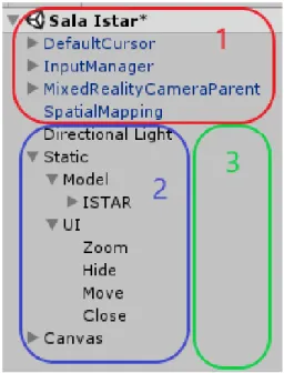
Figure 11 shows a hierarchic view of components used in the Unity project, including a classification to separate elements into three main sets – 1 is Mixed Reality, 2 Models and 3 Backend.
Mixed Reality components include pre-built game objects and scripts necessary for the MR application to run in MH, including prefabs imported with the Mixed Reality toolkit. Models set includes all the 3D Unity GameObjects (GOs) and meshes inserted in the Unity scene, which are visible to the user. Backend logic represents all the necessary script programming and connection between components that give life to the UI and ISTAR lab models. Figure 12 demonstrates an architecture overview of the Mixed Reality and Models described in this paragraph, the way MH’s hardware is handled by Unity GOs and the connections between GOs themselves. The GestureInput GO handles clicks in UI, the SpatialMapping GO is dependent of the GazeManager, and the InputManager and MixedRealityCamera handle the projection and all interaction with the ISTAR, UI and Canvas GOs. For Backend, a different logical representation of the system is presented in Figure 23 of 3.2.3.
Figure 12 - InOffice architecture overview
3.2.2. Features
InOffice opens with a model attached to the user’s gaze. When the user focuses on surfaces, MH recognizes the surfaces and sticks the model onto them. As soon as the air tap gesture is used, the hologram is anchored to the real world on the surface the user was looking at. After placing it, the user can then explore freely around the hologram as it is fixed on the surface (Figure 13 and Figure 14).
At this point, the user is able to see four different icons floating above the model which can be clicked on using the air tap gesture (Figure 14). These four icons represent the UI of InOffice and provide a user-friendly experience while using the application.
Figure 13 - User placing the model Figure 14 - Hologram fixed to table's surface
3.2.2.1. Move
The move icon (Figure 15) is used to reposition the hologram when needed. When clicked the model will reattach itself to the MH user’s gaze and MH will restart detecting nearby surfaces for the user to place the model on them.
Figure 15 - Move icon
3.2.2.2. Hide
Hide icon (Figure 16), when clicked will hide walls, ceilings, and floors, which makes it possible to visualize infrastructure that was previously hidden. This feature is shared with the InSitu application.
Both MR applications rely on 3D holographic views of infrastructure. This infrastructure can be compared with a living organism with veins and arteries, similar to the one projected in a hologram by researchers at the University of Lübeck [8], as shown in Figure 3. As previously mentioned in chapter I, one of the goals is to include the infrastructure components like wires, pipes, and vents in the hologram and this feature makes it possible to display and hide them to the user. This experience can be compared to [24], however, InOffice has the benefit of displaying infrastructure information directly to the MH lenses, providing the technician with the required information to proceed with his tasks without further inspection on site. Additionally,
this MR application can be used outside the building site as well as be manipulated with the Zoom (3.2.2.3) and Move (3.2.2.1) features.
Figure 16 - Hide icon
Figure 17 displays the result of clicking the hide icon once, revealing all the hidden air ducts above the ISTAR laboratory building model. A second click will reactivate walls and ceilings, returning the model back to its original state.
Figure 17 - Hide feature active, elements marked in the XML file as transparent are hidden
3.2.2.3. Zoom
The zoom feature (Figure 18) is activated with an air tap and hold gesture (emulating a click and drag with a mouse). If the hand is dragged to the right, the model will start to increase its scale on all axis and the icon will change to a green plus sign inside a magnifying glass (Figure 19). Otherwise, if the hand is dragged to the left, the model will start to shrink and the icon displayed will be a green minus sign inside the magnifying glass (Figure 20).
3.2.2.4. Close
The close feature (Figure 21) is a quick way to shutdown InOffice. A single click on this icon will terminate the running application without the need to use the bloom gesture.
Figure 21 - Close icon
3.2.2.5. Display BIM information
The final feature available in InOffice and InSitu is the display of information on the MH. The MH display is treated as a Head-Up Display (HUD) to show 2D information of the building element the user is focusing on with the MH cursor.
The information is displayed in the top left section of the lens, as seen in Figure 22.
Figure 22 - Information of an element in the building Figure 19 - Zoom in
3.2.3. Implementation
This section details technical contributions from the implementation of InOffice, in chronological order of elaboration.
Figure 23 represents the logical system created for InOffice. Each logical flow between objects and classes is detailed in the appropriate subheading of this section.
Figure 23 - InOffice's logical system
3.2.3.1. Export building model from Revit to Unity
On completion of the 3D BIM modelling of the ISTAR laboratory in Revit, two methods were chosen to export the model into a Unity project. The first method consists of exporting the geometry to an FBX file using the standard Revit tool and Unity is able to import the FBX file onto the project assets. However, this method does not hold building textures and materials in the exported file due to a deficiency in the Revit FBX file converter, leaving the Unity model bland with standard white materials and no textures. To remedy this, the 3D modelling software 3dsMax is used as middleware to correctly convert the FBX file that once opened in Unity will contain all materials and textures.
The steps to export the FBX file from Revit to Unity are: 1. Export the FBX file from Revit;
3. Save and export a new FBX file from 3dStudioMax; 4. Import the FBX file to Unity.
3.2.3.2. Unity scene setup
Every MH Unity project requires a camera positioned in the origin of the scene with a black background and near clipping planes. The black colour in HoloLens camera is made transparent at runtime, which enables visibility of the holograms and the real world at the same time. The MRTK provides tools that automatically configure the Unity scene and project settings for a MH application (Figure 24).
Figure 24 - Mixed Reality Toolkit automatic configuration for MH applications
The project’s player settings defined enable Windows Mixed Reality support. The project’s scene, as demonstrated in Figure 11 and Figure 12, consists of the required Mixed Reality Camera, an InputManager GO that can interpret hand gestures, and a SpatialMapping GO for surface recognition.
The custom GO ISTAR contains the FBX file imported from 3dsMax which represents a 3D model with all the building elements, material, and textures. The GO UI is divided into four GOs: Hide, Zoom, Move, and Close. Each of these GO represents a feature in this application and they all have scripts associated with them as seen in the logical system (Figure 23). The GO Canvas has a child GO named Text, that holds the information of the element focused in the building at runtime.
3.2.3.3. Export XML with building information from Revit to Unity
Every element in BIM has a large number of properties that can be defined in Revit. To export BIM information, Dynamo is used to create a Python script which generates an organized XML file with selected information (Figure 25). For these MR applications, the information selected and published to the XML file is shown in Table 1. The id is a unique identifiable integer that matches the object’s name in Unity, therefore making it possible to associate information from BIM with the Unity model.
The category of the element is its commonly used name, such as “Walls” or “Windows”, this category field does not specify the properties of each element. The family of a certain component is the classification of the element in the industry, for example, a lamp’s family can be “M_Downlight - Rectangle – LED” and a wall’s family can be “Interior Wall Light_100_LC”. These family names are used by the manufacturer of these parts and can include properties of the element in its name. Mark is a property of each element in Revit that is user-defined. This field is used to show additional information on each infrastructure component, examples of information entered are the date of next inspection on fan coils, date of next cleaning in air ducts and an additional property for all doors. The Transparent field is not available in Revit, as it is generated in the Dynamo’s Python script. This field is used to mark which elements are hidden when using the Hide feature.
A full screenshot of the Dynamo’s script is attached in Appendix A.
Table 1 - Properties of each element in the XML Element Id Category Family Transparent Mark
For MH to read and load the XML file, the following algorithm was conceived into a C# script for Unity:
The Dictionary is used as the dataset to store the XML information since the accesses to it are made using key values and not an index value [38].
The class responsible to load the XML file is the LoadXML in Figure 23. This class stores the full dataset in a private Dictionary, which can be accessed from a public method “getListFromId(string)”. This method is used in the class OnFocusInfo to fetch information about the focused element at runtime. To make sure LoadXML’s public instance is available at runtime, it is attached to ISTAR’s GO. One of the major challenges was researching a way to read files from MH’s device itself. The reason the XML file is not downloaded from an online server is to allow InOffice to work offline, without requiring an internet connection to function properly. Before InOffice is running, the XML file needs to be placed in the correct folder inside MH. The path chosen is the CameraRoll folder, which is a Windows folder of MH accessible with core .NET libraries, therefore, the condition “if NETFX_CORE…endif” encapsulates all usages of the library Windows.Storage.
Get XML from file path;
Declare new Dictionary<string, Dictionary<string,string>> XML; For each element in XML:
Declare new Dictionary<string,string> Attribute; For each tag in element:
If tag.name = “id” id = tag.value; else
Attribute.Add(tag.name, tag.value); XML.Add(id, Attribute);
The folder Camera Roll can only be read at runtime if the Unity project is published with the PicturesLibrary capability active (Figure 26). This folder is available in the online File Explorer of MH.
Figure 26 - Capabilities in publishing settings of Unity's Player settings
3.2.3.4. Placing the hologram
Surface detection is a key need to make sure the hologram can be easily placed on a regular surface. The MRTK has a spatial mapping prefab that enables this feature, placing it in the active Unity scene activates it.
The SpatialMapping GO (Figure 12) uses the four environmental sensors of MH to scan and map the surface captured. This is a core HoloLens feature and does not require custom development. The settings used with this prefab can be seen in Figure 27.
With surface recognition active, and the ISTAR laboratory model in the scene, the TapToPlace script by MRTK is attached to the ISTAR model.
This class implements the interface IInputClickHandler, and when triggered with a click event, it attaches the model to the MH’s gaze until the user places it in the world with an air tap gesture. For the application InOffice to start with the model immediately attached to the user’s gaze, the flag “isBeingPlaced” is set to true in Unity (Figure 28).
Figure 28 - TapToPlace class settings
3.2.3.5. User Interface
InOffice’s UI is a core aspect of the solution, it is built to be user-friendly and intuitive. The icons chosen to represent possible interactions with the hologram are available in the Unity Asset Store [39], each icon chosen is directly associated with its function. This reduces the need to include a subtext beneath each icon explaining what it does or how it’s used.
When the user looks at any of the icons, they are highlighted with a change of colour to grey and increased size in 10%. Additionally, a Billboard script from MRTK ensures the icons are always facing straight at the MH user.
Each of the buttons in InOffice has a C# script associated (Figure 23), all of which implement the interface IInputClickHandler (MRTK). This interface handles the event of an air tap gesture when the gaze is in the direction of the button.
3.2.3.5.1. Move
The move script “OnMove” (Figure 23) simulates a new TapToPlace click event, which reattaches the ISTAR model to the user’s gaze. Since the SpatialMapping feature of HoloLens is active, the model will stick the surfaces it detects until the user decides to stick the hologram to the real world.
3.2.3.5.2. Zoom
The zoom script “OnZoom” (Figure 23) implements the IManipulationHandler (MRTK) interface, which can handle the hold gesture used after an air tap. To zoom in or out of the model, the following formula is applied to each component in the scale vector of the model (x, y, and z):
CumulativeDelta represents the delta distance between the initial position of the hand when the hold gesture is started and the final position of the hand when the gesture is finished. When the hand moves to the right, cumulativeDelta has a positive value, and when the hand moves to the left it has a negative value, therefore, decreasing the scale vector.
3.2.3.5.3. Hide
The Hide script “OnHide” (Figure 23) accesses the Dictionary dataset with the loaded XML file in the instance “LoadXML” to decide which elements in the model to deactivate when this feature is triggered.
Algorithm conceived to hide the objects:
This feature has an active mode, stored in a private bool variable of the class “OnHide”. When the user clicks the Hide button, the walls, ceilings, and doors will be shown or hidden depending on the value of the variable.
Scale.x = currentScale.x + (cumulativeDelta.x * 0.05f)
For each child object in ISTAR model: Get id from object’s name;
XML.TryGetValue(id, out attributes); //Access Dictionary with XML from id
attributes.TryGetValue("Transparent", out isTransparent)) //Get Transparent element If isTransparent != null
3.2.3.5.4. HUD
The BIM properties are displayed in a HUD in HoloLens. This requires that every element in the ISTAR GO has a Box Collider and a focus handler to catch and treat focus events triggered when the user’s gaze is directed at each element. Box colliders in Unity are 3D invisible boxes that are necessary to detect gaze or gesture inputs aimed at the element.
The conceived script “OnFocusInfo” (Figure 23) implements the IFocusable interface (MRTK) which is triggered every time a GO with this script is focused on. The instance then fetches all the attributes stored in the Dictionary dataset for the focused object with the method TryGetValue, available in “LoadXML”. For each property found, its text value is stored in Unity Text GOs which are displayed in the scene’s Canvas.
The Canvas is placed directly one meter in front of the MR camera (position – x: 0; y: 0; z: 1), and the properties required to ensure it functions as a HUD are described in Figure 29.
Figure 29 - Canvas properties to form HUD
The Canvas’ settings that transform it into a HUD are the Render Mode and Camera selected. These settings make sure any Unity UI objects are displayed in the Mixed Reality Camera’s screen.
3.3. InSitu
The InSitu application can evolve from the left to the right side of the RV continuum [6]. Its environment can be considered a mix of virtual and real elements since both the hologram and parts of the real world compose the environment. It may be considered Augmented Reality, however, the more virtual elements compose InSitu’s environment the more it evolves in the spectrum into an Augmented Virtuality application.
The name InSitu derives from the Latin expression in situ. This application is meant to be used on site, i.e. inside the building being observed and analysed.
3.3.1. Architecture
The InSitu architecture is similar to InOffice's with the addition of the Vuforia toolkit. Figure 30 shows a hierarchic view of components used in the Unity project – 1 is Mixed Reality which includes the Vuforia prefabs, 2 is Models and 3 Backend.
Figure 32 demonstrates an architecture overview of this application. The main difference between this system and InOffice’s is the added Vuforia GameObjects. The ARCamera prefab consumes the 2MP camera available in MH to detect ImageTargets defined by the user. These ImageTargets are personalized images that must have clear defining features so that the camera can easily detect them. For InSitu, a QR code was generated, and according to Vuforia, it meets the requirements to be an excellent augmentable ImageTarget (Figure 31).
For Backend details, a logical representation of the system is presented in Figure 38 of 3.3.3.
Figure 31 - QR Code features and Vuforia rating
Figure 32 - InSitu architecture overview
The downside of using Vuforia is that the camera used to take photos and record video or live stream is constantly occupied at runtime, which means it is not possible to capture the real experience of users with InSitu. The MH can only capture the holograms projected without the real world beneath.
3.3.2. Features
InSitu opens with a message on the screen – “Search for the QR code”. When the user focuses on the QR code placed in the ISTAR laboratory, Vuforia uses that marker to align the virtual ISTAR model with the real laboratory. The hologram is shown in its real location and the user can explore this 1:1 scaled model of the building he’s in (Figure 33 and Figure 34).
Figure 33 - User exploring real scaled hologram visible to the user superimposed on the reality Figure 34 - InSitu's 1:1 hologram which is
3.3.2.1. Hide
Located in the table at the centre of ISTAR (Figure 35), the hide icon is available to perform the same functionality as InOffice, deactivate all the walls, ceilings and floors to reveal hidden infrastructure in their real-world location (Figure 36).
Figure 36 - X-ray vision to reveal infrastructure in the ceiling
3.3.2.2. Display BIM information
Equivalent to InOffice, InSitu provides the user with a HUD view of information on each object of the model he focuses on. Figure 37 demonstrates how this looks in the first person view in InSitu.
All these features combined create a seemingly virtual scenario, which can be compared to [11], as the MH can project the 3D model of the ISTAR laboratory in real scale, and the user walks in a virtual representation of ISTAR.
3.3.3. Implementation
This section details technical contributions from the implementation of InSitu. The Unity setup, the hide feature, and the HUD with BIM information were previously detailed in InOffice’s section of this development chapter.
Figure 38 represents the logical system created for InOffice. Each logical flow between objects and classes is detailed in the appropriate subheading of this section.
Figure 38 - InSitu's logical system
3.3.3.1. Unity scene setup
InSitu’s Unity project also requires Mixed Reality support, as such it starts similar to InOffice’s project – explained in 3.2.3.2. The differences made for InSitu regard the UI since this application requires less interaction it has fewer button features, and most importantly it adds Vuforia prefabs to the scene.
The GO UI simply consists of the GO Hide which has the same functionality as InOffice’s Hide (3.2.3.5.3).
Setting up the Vuforia scene requires a development license key and upload of an image target to their server. Figure 39 shows the configuration needed to enable Vuforia with MH. The ARCamera GO is added to the origin of the scene, with its behaviour script settings as seen in Figure 40.
Figure 39 - Vuforia configuration for MH
Figure 40 - Vuforia's behaviour script settings
3.3.3.2. Aligning virtual model with real building
InSitu’s main development challenge is the method of aligning the virtual 3D model of ISTAR laboratory with the real world, to make sure every infrastructure component modelled is placed in the correct position in relation to the MH user.
MH has spatial mapping tools and the MRTK provides spatial understanding scripts, combining these two makes it possible to create an application that can map the surrounding environment in real time whilst aligning the virtual model with the mapped surface, however it is not yet a trustworthy solution [40]. For this approach to be viable, MH would need upgraded sensors to accurately map irregular surfaces.
A second possible way to align models is through a two-point alignment system [26]. Even though the method is a solid approach to align a virtual 3D BIM with the real world without requiring constant use of MH to map, observe, understand and align models.
The solution adopted for InSitu uses the Vuforia toolkit [36] and a marker to position the virtual model in the correct place.
The marker is a Vuforia ImageTarget, which can be added to Unity as a GO. However, the placement and scale of this ImageTarget in the virtual model, as well as in the real world is the key to configure the initial alignment between virtual and reality. The QR Code image used is the size of an A4 paper, which makes it easier to print and place in the real world. When the ImageTarget is imported to Unity, it must be readjusted accordingly with the model being placed in the real world.
Choosing the correct placement spot for the QR Code is essential to ensure perfect alignment, for this application a desk’s edge was used as a point of reference (Figure 41). This point of reference works well since it’s easy to locate it in the real world while using, for example, the centre of a round desk would be more prone to human error. The ImageTargets can be used to augment any imported 3D model to Unity, as long as the GameObjects of those models are children of the ImageTarget GO (Figure 42).
Figure 41 - Placement of the image target
Figure 42 - ImageTarget GameObject and children
After the initial placement of the augmented 3D model into the real world, the MH can take over the alignment task and continue showing the rest of the virtual model without the ImageTarget in the camera’s gaze. This is accomplished with Vuforia’s Extended Tracking [41]. Extended Tracking means the augmented model can remain displayed on the tracking device, MH in this case, even after the ImageTarget is outside the field of view of the ARCamera. Using Vuforia’s Extended Tracking, MH only needs Vuforia to anchor the model in the real world once using the marker for alignment. After recognition of the marker, MH activates its spatial mapping features and displays the rest of the 3D model without that anchor point since it starts creating his own.
This solution produces an outcome similar to the two-point alignment system [26], as it doesn’t require constant processing of the MH for spatial mapping and spatial observing, but it has a faster setup – the only step required to align the models is
looking directly to the Vuforia marker with the MH, and it doesn’t require a UI to align the model making it a simpler and faster method to implement.
The InSitu application requires the placement of a single marker, which decreases the setup time needed and the usability of it compared to Xue’s multiple marker solution [18].
3.3.3.3. Display BIM information
Although the script “OnFocusInfo” to fetch information from the XML file is the same as InOffice, the canvas used for InSitu has different properties since Vuforia requires the use of a second camera. Vuforia’s ARCamera is always actively searching for the marker to calibrate and adjust the model it’s attached to. The canvas properties were adjusted as seen in Figure 43. To make sure the HUD is displayed at runtime, the ARCamera is used as the Canvas instead of the MR camera.
![Figure 1 - The construction industry is among the least digitized [2]](https://thumb-eu.123doks.com/thumbv2/123dok_br/19181767.945687/17.892.193.701.574.1031/figure-construction-industry-digitized.webp)
![Figure 2 – Virtuality Continuum, image from [7]](https://thumb-eu.123doks.com/thumbv2/123dok_br/19181767.945687/18.892.238.657.906.1118/figure-virtuality-continuum-image-from.webp)
![Figure 3 - Holographic view of the interior of a human body's replica [8]](https://thumb-eu.123doks.com/thumbv2/123dok_br/19181767.945687/19.892.207.687.794.1033/figure-holographic-view-interior-human-body-s-replica.webp)
![Figure 4 - Real world setup visualized in a Virtual Reality scenario [11]](https://thumb-eu.123doks.com/thumbv2/123dok_br/19181767.945687/20.892.173.721.106.396/figure-real-world-setup-visualized-virtual-reality-scenario.webp)
![Figure 5 - User interface for military training using markers and HoloLens [18]](https://thumb-eu.123doks.com/thumbv2/123dok_br/19181767.945687/21.892.161.733.738.1113/figure-user-interface-military-training-using-markers-hololens.webp)
![Figure 6 - Mixed reality video conference [21]](https://thumb-eu.123doks.com/thumbv2/123dok_br/19181767.945687/22.892.211.681.660.1004/figure-mixed-reality-video-conference.webp)
![Figure 7 - Visual representation of what the worker can see [23]](https://thumb-eu.123doks.com/thumbv2/123dok_br/19181767.945687/24.892.129.766.105.463/figure-visual-representation-worker.webp)
![Figure 8 - Two virtual coordinates, white and red to be aligned [26]](https://thumb-eu.123doks.com/thumbv2/123dok_br/19181767.945687/25.892.132.777.129.314/figure-virtual-coordinates-white-red-aligned.webp)