1
An Overview on the Reactors to Study Drinking Water Biofilms
1
2
Gomes, I. B.a, Simões, M.a and Simões, L. C.a,b* 3
4
a LEPABE, Department of Chemical Engineering, Faculty of Engineering, University of 5
Porto, Rua Dr. Roberto Frias, s/n, 4200-465 Porto, Portugal 6
b CEB- Centre of Biological Engineering, University of Minho, Campus de Gualtar 4710-7 057 Braga, Portugal. 8 9 10 11 12 13 14 15 16 17 18 19
*Corresponding author: Lúcia C. Simões, Centro de Engenharia Biológica, Universidade do 20
Minho, Tel: 00351 253604404. Fax: 00351 253678986. E-mail: [email protected] 21
22
ABSTRACT 23
This article was published in Water Research 62, 63-87, 2014 http://dx.doi.org/10.1016/j.watres.2014.05.039
2 The development of biofilms in drinking water distribution systems (DWDS) can cause pipe 24
degradation, changes in the water organoleptic properties but the main problem is related to 25
the public health. Biofilms are the main responsible for the microbial presence in drinking 26
water (DW) and can be reservoirs for pathogens. Therefore, the understanding of the 27
mechanisms underlying biofilm formation and behavior is of utmost importance in order to 28
create effective control strategies. As the study of biofilms in real DWDS is difficult, several 29
devices have been developed. These devices allow biofilm formation under controlled 30
conditions of physical (flow velocity, shear stress, temperature, type of pipe material, etc), 31
chemical (type and amount of nutrients, type of disinfectant and residuals, organic and 32
inorganic particles, ions, etc) and biological (composition of microbial community – type of 33
microorganism and characteristics) parameters, ensuring that the operational conditions are 34
similar as possible to the DWDS conditions in order to achieve results that can be applied to 35
the real scenarios. The devices used in DW biofilm studies can be divided essentially in two 36
groups, those usually applied in situ and the bench top laboratorial reactors. The selection of 37
a device should be obviously in accordance with the aim of the study and its advantages and 38
limitations should be evaluated to obtain reproducible results that can be transposed into the 39
reality of the DWDS. The aim of this review is to provide an overview on the main reactors 40
used in DW biofilm studies, describing their characteristics and applications, taking into 41
account their main advantages and limitations. 42
43
Keywords: Biofilm control; Biofilm monitoring; Drinking water; Reactor 44
1. Introduction
45
There is a global concern that all the world population should have access to safe drinking 46
water (DW). Even in the 21st century, there are many people without access to appropriate 47
3 water, in quantity and/or quality, for the basic needs (WHO, 2011). The existence of DW 48
distribution systems (DWDS) allows the management and supply of water for more people. 49
However, there are several problems that can occur in a DWDS. From a microbiological 50
perspective, the main problems reported in DWDS are the biocorrosion, biofilm formation, 51
nitrification and also the occurrence and persistence of pathogenic organisms (Beech and 52
Sunner, 2004; Camper, 2004; Emtiazi et al., 2004; Simões and Simões, 2013; Teng et al., 53
2008). Biofilms are considered to be the main source of microorganisms in DWDS that are 54
fed with treated water (Berry et al., 2006; Yu et al., 2010). Biofilms are a set of 55
microorganisms attached to a surface through exopolymers they produce, also known as 56
extracellular polymeric substances (EPS). These are mainly proteins and polysaccharides that 57
are involved in microbial protection from stress conditions (Fang et al., 2010). The main 58
microorganisms that are commonly detected in water are heterotrophic bacteria, particularly 59
α-,β- and γ-proteobacteria (Berry et al., 2006), mycobacteria, some filamentous fungi, virus 60
and helminths (Abe et al., 2011). The existence of inorganic matter, like corrosion products, 61
clays and sand, can be responsible for changes in biofilm structure, increasing its mechanical 62
cohesion (Melo and Bott, 1997). Biofilms occur usually on surfaces which are in contact with 63
water. So, biofilm formation is common in DWDS. Wingender and Flemming (2004) stated 64
that 95% of water microorganisms are present in DWDS inside biofilms while only 5% are 65
floating in the bulk phase. 66
Although biofilms are the main form of microbial organization in nature, the formation of 67
these structures in DWDS depends of several biotic and abiotic factors, namely 68
environmental factors (temperature and pH), concentration of residual disinfectants, nature 69
and concentration of nutrients, hydrodynamic conditions (flow rate, design of network and 70
presence of dead ends), type of pipe materials and their conservation state, type and diversity 71
4 of microorganisms present and sediment accumulation (Deines et al., 2010; Jang et al., 2011; 72
Simões and Simões, 2013; Yu et al., 2010). The biofilm formation process occurs in several 73
steps (Fig. 1) (O'Toole et al., 2000). The preconditioning of the pipe surface by organic and 74
inorganic macromolecules facilitates the bacterial adhesion process. Thereafter, cells can 75
adsorb to the surface reversibly or irreversibly (a). After adhesion, a stage of active biofilm 76
growth occurs by cell replication, EPS production, release of quorum-sensing (QS) 77
molecules and exchange of substances between the biofilm and the bulk (b and c). The 78
biofilm dispersion and formation/colonization in other clean areas can take place after 79
biofilm detachment from pipes walls, as depicted in Fig. 1 (d, e and f) (Codony et al., 2005). 80
The amount of a biofilm in a given system, after a certain period of time, depends on a 81
dynamic biofilm formation process, which has been defined as the balance between bacterial 82
attachment from the planktonic phase, bacterial growth within the biofilm and dynamic 83
detachment from the surface (Stoodley et al., 1999). When the balance is null, the biofilm is 84
said to have reached a steady-state. The final amount of biofilm in that state, which can be 85
assessed by cell counts or biomass determination, is directly related to its formation potential 86
in the system (Van der Kooij, 1999). Hydrodynamics have an utmost role in biofilm 87
development and in determining its stability (Bott, 1993). The flow rate affects biofilm 88
development by interfering with several phenomena, namely: nutrients transport, bacterial 89
adhesion, biofilm growth and detachment (Characklis and Marshall, 1990). When the flow 90
velocity is low there is a high resistance to mass transfer (nutrients, oxygen, etc.) from the 91
bulk fluid to the microorganisms embedded in biofilms, impairing sessile cell growth. On the 92
other hand, high flow velocity causes high turbulence of the fluid bulk. It means that the mass 93
transfer phenomena are enhanced, improving also the biofilm growth. However, high 94
velocity also causes high shear forces that can be responsible for higher biofilm erosion and 95
5 detachment; accordingly it may cause a decrease of biofilm mass on surfaces. Therefore, 96
apart from others factors, studies on the effects of hydrodynamic conditions are also very 97
important to understand biofilm formation in DWDS. However, the hydrodynamic 98
conditions (flow rate, velocity, residence time, shear stress) are dependent of the geometry 99
of each biofilm reactor. The dimensionless Reynolds number (Re), in fluid mechanics, is 100
defined as the ratio of inertial forces to viscous forces and is used to describe the flow 101
conditions of a fluid (laminar, transition and turbulent flow). Its calculation is dependent of 102
the reactor flow geometry. Also, the definition of laminar and turbulent flow regimes varies 103
according to the system used. The Re number for the flow in a pipe or tube can be defined 104
by Eq. (1) and (2) where DH is the hydraulic diameter of the pipe (m), ρ is the fluid density
105
(kg.m-3), 𝑣 is the flow velocity (m.s-1), µ is the dynamic viscosity of fluid (N.s.m-2), A is the 106
pipe cross sectional area (m2) and P is the wetted perimeter (m). The wetted perimeter for a 107
pipe is the perimeter of the pipe wall that is in contact with the water flow. 108 𝑅𝑒𝑝𝑖𝑝𝑒 = 𝜌𝑣𝐷𝐻 𝜇 (1) 109 𝐷𝐻 = 4𝐴𝑃 (2) 110
In cylindrical pipes, Re < 2300, 2300 <Re < 4000, Re > 4000, correspond to laminar, 111
transition and turbulent flow conditions, respectively. The Re number for a stirred tank is 112
defined by the Eq. (3) where N is the rotational velocity and D is the diameter of agitator. For 113
an agitation situation the laminar flow is considered when Re < 10 and turbulent flow for Re 114 > 104 (Pérez et al., 2006). 115 𝑅𝑒𝑠𝑡𝑖𝑟𝑟𝑒𝑑 𝑡𝑎𝑛𝑘= 𝑁𝐷 2𝜌 𝜇 (3) 116
One of the major obstacles to study biofilms within DWDS is how to choose a suitable 117
experimental system that mimics the conditions found in real pipe networks. A number of 118
6 devices have been described in literature for studying biofilms in DWDS. Therefore, the aim 119
of this review is to provide an overview on old and well described and reviewed biofilm 120
reactors as well as on new or more recently developed reactors that not have been reviewed 121
together yet. The diverse devices are described as well as aspects on their limitations and 122
advantages. Also, a brief description on the main applications of reactors in DW biofilm 123
studies and the quantification methods used for DW biofilm characterization is provided. 124
Nevertheless, the complexity of the DWDS microenvironment and even the use of different 125
methodologies and biofilm reactors have led in some cases to ambiguous or not easily 126
comparable results. Most studies assessed only one variable at a time, and apart from notable 127
exceptions, few attempts have been made so far to study their inter-relationships and compare 128
the relative importance of these different factors. 129
130
2. Bench top laboratorial devices
131
Several devices were developed to study biofilms autonomously from DWDS. These devices 132
try to mimic the DWDS behavior, allowing testing different conditions and can be fed with 133
tap water or with appropriate medium or enriched water. In fact, these devices are DWDS 134
models used to achieve a diversity of goals. However, they were used mostly in laboratorial 135
experiments. 136
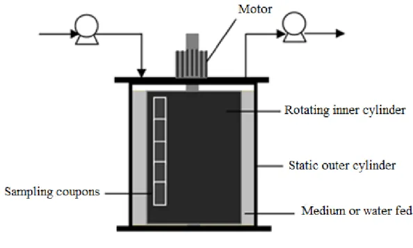
2.1. Annular Reactor
137
The annular reactor can operate as an open/continuous system and has been used for several 138
decades for the development of biofilms under turbulent flowing environments (Morin and 139
Camper, 1997; Volk and LeChevallier, 1999). It is a simple reactor that mimics the 140
hydrodynamic behavior that biofilms are subjected in real DWDS (Batté et al., 2003a; 141
Keinänen-Toivola et al., 2006). This reactor, also known as Rototorque®, is constituted by 142
7 two cylinders, one static external cylinder and other rotating internal cylinder whose speed 143
is controlled by a motor (Chandy and Angles, 2001; Fang et al., 2010; Hosni et al., 2011; 144
Morin and Camper, 1997; Zhou et al., 2009). Usually, the inner cylinder supports some 145
coupons used to sample the biofilm (Fig. 2). The rotation of the inner cylinder is controlled 146
in order to define the desired shear stress. The relationship between shear forces, the cylinder 147
diameter and the rotational speed is provided in Table 1. However, the equations are a gross 148
simplification of the annular reactor shear stress determination, since its calculation for this 149
particular system is quite complex. 150
The shear stress usually described as characteristic of DWDS pipes is 0.25 N.m-2 that is 151
equivalent to 0.3 m.s-1 in a 100 mm diameter pipe; these conditions are often reproduced in 152
the annular reactor (Butterfield et al., 2002; Fang et al., 2010; Gagnon et al., 2004, 2005; 153
Jang et al., 2011, 2012, Morin and Camper, 1997; Murphy et al., 2008; Pintar and Slawson, 154
2003; Szabo et al., 2007). One value of flow velocity that is also often used is 0.6 m.s-1 (Batté 155
et al., 2003a, 2003b; Sharp et al., 2001). Rand et al. (2007) tested a shear force of 0.68 N.m -156
2 to assess the efficiency of chlorine dioxide or chlorinecoupled with UV treatment on DW 157
biofilm control. The data shown that, the combination of chlorine dioxide/UV was the most 158
effective strategy against both suspended and attached bacteria. Altman et al. (2009) studied 159
the integration and retention of planktonic pathogen Bacillus cereus in a Pseudomonas 160
fluorescens biofilm under a range of different hydraulic conditions (from 0.15 to 1.5 N.m-2 161
or from 50 to 300 rpm). The authors found that the amount of pathogens detected in the 162
biofilms was higher in the mid-shear range. 163
This reactor also has been used to study the influence of temperature on biofilm development. 164
Some annular reactors have a jacket allowing working at the desired temperature. Pintar and 165
Slawson (2003) tested different temperatures (6, 12 and 22 ºC) and different concentrations 166
8 of disinfectant residual (chloramination) being the reactor fed with tap water and working at 167
constant rotation speed (50 rpm) providing a shear stress of 0.25 N.m-2. The results clearly 168
indicate that biofilm development occurs at all examined temperatures, as well as at the 169
selected monochloramine residuals. However, the maintenance of a disinfectant residual had 170
more biofilm inhibitory effects than that of the low temperature. Ndiongue et al. (2005) also 171
studied the effect of temperature (6, 12 and 18 ºC) and biodegradable organic matter on 172
biofilm control by chlorine at 92 rpm. Overall, the results shown that both temperature and 173
nutrients levels are important factors that must be considered when using free chlorine 174
residual to control DW biofilms. 175
With the aim to perform different studies and save resources, variations of the conventional 176
annular reactor were developed. An example is the conical annular reactor. A standard 177
annular reactors provides a constant wall shear stress distribution on surfaces, while a conical 178
annular reactor generates a non-uniform distribution of this hydrodynamic strength. Rochex 179
et al. (2008) used a conical annular reactor (CCTR - Conical Couette-Taylor reactor) to 180
develop biofilms at varying shear stresses (0.055 to 0.27 Pa from bottom to top of the reactor) 181
with only one device and provided a useful model for studying the effect of hydrodynamics 182
on biofilms. These authors also evaluated the effects of shear stress on the bacterial biofilm 183
community composition. The results shown that, high shear stresses decreased biofilm 184
diversity and slowed down its maturation, maintaining the characteristics of young biofilms. 185
The use of annular reactors to study DW biofilm development and control can be 186
advantageous, mainly if the objective of the work is to study the material influence (allows 187
the study of different materials at the same time) or the effect of hydrodynamics. This reactor 188
also allows to take a considerable number of samples for each assay and has an easy sampling 189
process. The control of shear stress and linear velocity is also simple since it is determined 190
9 by the rotational velocity of the internal cylinder and thereafter it is independent from the 191
water flow rate fed to the reactor. So, the residence time and loading rate can be controlled 192
independently. Nevertheless, as referred above, the description of hydrodynamic equations 193
in annular reactors is complex once the flow on cylindrical surface is not well defined due to 194
the presence of Taylor vortices (Childs, 2011). Therefore, the shear stress is not uniform in 195
all surfaces available for biofilm formation. 196
197
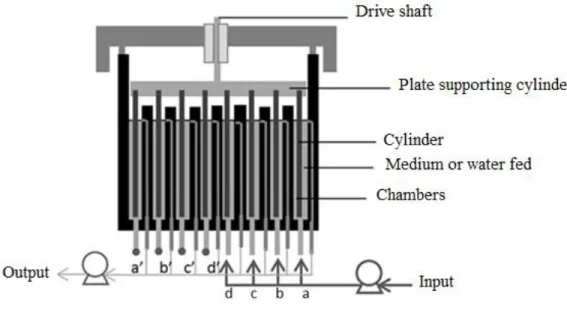
2.2. Concentric cylinder reactor
198
The concentric cylinder reactor (CCR) was firstly described and used to study biofilm 199
formation in the dairy industry (Willcock et al., 2000). This reactor allows the simultaneous 200
generation of different shear rates on the same inoculating population (Willcock et al., 2000), 201
but not with the same water phase since the four chambers are fed independently (Fig. 3). 202
Latter, this reactor was used to study DW biofilms by Rickard et al. (2004), who described 203
the effects of different shear forces on DW biofilms formation and its impacts on the 204
microbial community diversity. This reactor is composed by four rotating cylinder pipes and 205
four stationary cylinder chambers (Fig. 3). The chambers can be feed with tap water and the 206
volume inside the chambers is constant and controlled with the help of external pumps, being 207
the feeding ports different from the outlet and sampling ports. The shear stress is controlled 208
with the rotational velocity and radius of the cylinders. Rickard et al. (2004) used this reactor 209
with cylinders whose diameter was 101, 77, 50 and 26 mm that corresponds to fluid velocity 210
of 0.26, 0.19, 0.16 and 0.12 m/s and shear rates of 305, 198, 122 and 65 s-1, respectively. The 211
rotational speed of cylinders was kept constant during all the work (43 rpm), while the shear 212
force varied with the radius of the rotating surface. The fluid velocity profiles were 213
determined on the basis of computational fluid dynamics and from each fluid velocity profile, 214
10 shear rates were calculated. The results demonstrated that shear rates affect biofilm diversity 215
as well as the relative proportions of aggregating bacteria. An inverse relationship between 216
shear rate and biofilm diversity was found and the proportions of aggregating bacteria in 217
biofilms also change in relation to shear rates. The authors suggested that it is likely that such 218
cell-cell interactions aid in the integration of bacteria in flowing environments. 219
This reactor is interesting to study simultaneously the effects of different shear stresses on 220
DW biofilm, allowing to mimic what happens with DWDS since along the distribution 221
system there are variations on water flow velocity. However, it only allows studying one 222
material for each assay and the sampling process is not very easy, since it is necessary the 223
harvesting of biofilm samples from the cylinder surface. 224
225
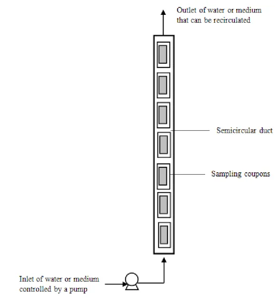
2.3. Flow cell system
226
The flow cell system consists in a duct segment where removable coupons are inserted in the 227
inner wall, whose allows the biofilm sampling over time. But, this system may present 228
different configurations. The flow cell reactor can be a semicircular duct with some coupons 229
(only the upper face contacts with water) located on the flat wall and the flow pass-through 230
the duct from the bottom to top (Fig. 4). Another flow cell configuration can be a parallel 231
plate flow cell reactor, which consists in a rectangular flow channel with small removable 232
coupons inside, to monitor biofilm formation (Huang et al. 1992). Usually, the flow cell 233
reactor is provided by a feed/fresh water reservoir and the temperature can be controlled 234
externally. The flow is recirculated and the sampling process do not stop the flow because 235
outlet ports are located in the curved wall between two removal coupons, allowing the 236
deviation of flow (Manuel et al., 2007; Simões et al., 2006, 2012). Therefore, this system 237
also allows mimicking the DWDS conditions, since it is a versatile system that allows 238
11 periodical sampling, without stopping the flow, and the flow velocity can be controlled by 239
an external pump. However, the boundary of sampling coupons can change the water flow, 240
which can affect biofilm development. Flow cell reactors can be used to monitor biofilm 241
development and behavior face to different control treatments and also to test the influence 242
of different materials and hydrodynamic conditions on biofilm formation.This reactor also 243
can be used as an in situ device, acting as a by-pass in DWDS. As example, Simões et al. 244
(2006) used the flow cell reactor to monitor biofilms exposed to different operational 245
conditions. The flow cell reactor was fed with tap water without chlorine, previously removed 246
with activated carbon filters. The influence of diverse conditions on biofilm formation were 247
studied, namely the turbulent (4000 L.h-1, Re = 11000) and laminar (73 L.h-1, Re = 2000) 248
flow, the presence and absence of nutrients (C, P and N) and the type of surface materials, 249
stainless steel (SS) and polyvinyl chloride (PVC). This study allowed to conclude that from 250
the most relevant to the least relevant factor, the biofilms increased due to the addition of 251
nutrients to water; the use of turbulent instead of laminar hydrodynamic flow; and the use of 252
PVC instead of SS as the support material. 253
Manuel et al. (2007) studied the influence of different materials on biofilm development and 254
the effects of the flow and non-flow regimes on the growth of both attached and suspended 255
bacteria using a flow cell reactor. The reactor was fed with tap water at 15.1 mL.d-1 with 256
different Re numbers (5000 and 8293). Microbiological analysis showed that the support 257
material did not affect significantly biofilm growth. However, operating under continuous 258
flow (0.8-1.9 Pa) or stagnant water had a significant effect on biofilm formation: in stagnant 259
water the biofilm grew to a less extent. The same authors assessed how hydraulic conditions 260
(stagnation or flushing) can affect the biological stability of biofilms and evaluated the 261
relationship between the stability and the microbial composition of biofilms using a flow cell 262
12 reactor. Continuous turbulent (Re = 4900, 6 L.min-1) and laminar (Re = 810, 1 L.min-1) flow 263
regimes were used and biofilm formation was monitored for 20 days. Afterwards, the system 264
was subjected to unsteady hydraulic conditions (Manuel et al., 2010). Independently of the 265
flow regime under which the biofilm was formed, stagnation promoted bacterial 266
accumulation, either as attached or suspended forms, which were carried away in higher 267
numbers when flow was re-started, thereby compromising the biological quality of the water. 268
In all cases, Betaproteobacteria was the dominant phylogenetic group, although Gamma and 269
Alpha subclasses were also present. These results suggest that special attention should be 270
given to the biological quality of DW when consumption is subjected to strong variable 271
demands (Manuel et al., 2010). 272
273
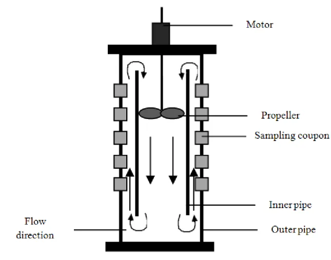
2.4. Propella® reactor
274
The Propella® reactor was already used by several authors for DW biofilms studies (Dailloux 275
et al., 2003; Gosselin et al., 2013; Lehtola et al., 2006, 2007; Rubulis and Juhna, 2007; 276
Simões et al., 2012; Torvinen et al., 2007). It consists of two concentric cylinders in which 277
the propeller pushes the liquid down through the inner tube and then up through the annular 278
section between both cylinders (Fig. 5). It is a perfectly mixed reactor and the fluid velocity, 279
hydraulic residence time and the flow rate are controlled by the rotation speed of the propeller 280
(Table 1). Coupons are usually located in the outer tube facilitating the sampling process and 281
in some cases the removal of coupons does not change the flow conditions. 282
The ability of this reactor to simulate the process conditions commonly found in real DWDS 283
makes it attractive for diverse studies. Dailloux et al. (2003) used a Propella® reactor with 284
2.08 L of volume (with high-density polyethylene (HDPE) coupons), water velocity of 0.2 285
m.s-1, fed continuously with tap water (83.5 mL.h-1) and inoculated with Mycobacteria 286
13 xenopi in order to evaluate the ability of this bacterium to colonize the experimental DW 287
biofilms. The authors verified that biofilms may be reservoirs for the survival of M. xenopi 288
and contributors to the continuous contamination of DW by erosion processes. Lehtola et al. 289
(2006) used Mycobacterium avium and a 2.3 L Propella® reactor with PVC coupons, working 290
at a flow rate of 183 mL.min-1 (Re = 15000, retention time = 12.6 h). And they concluded 291
that this bacterium is able to survive and grow in DW biofilms and possibly transmitted via 292
DW. The same reactor and the same conditions were used in other study to assess the survival 293
of M. avium, Legionella pneumophila and Escherichia coli in DW biofilms under high-shear 294
turbulent flow conditions (Lehtola et al., 2007). This study clearly proved that pathogenic 295
bacteria entering DWDS can survive in biofilms for at least several weeks, even under 296
conditions of high-shear turbulent flow, and may be a risk to water consumers. This reactor 297
also was used to study the influence of phosphorus concentration on biofilm development 298
(Rubulis and Juhna, 2007; Torvinen et al., 2007). Rubulis and Juhna (2007) used the 299
Propella® reactor with PVC coupons fed with DW, at 0.25 m.s-1 and retention time of 24 h, 300
aiming to assess the possibility to prevent biofilm formation by the removal of phosphorus. 301
Those experiments showed that removal of phosphorus to very low levels (< 1 µg L-1) was 302
not an efficient strategy to eliminate bacterial regrowth and biofilm formation in DWDS. 303
Torvinen et al. (2007) studied the influence of low phosphorus concentration, flow rate and 304
temperature on the survival of M. avium in DW biofilms using a Propella® reactor with PVC 305
coupons (185 mL.h-1; 0.24 m.s-1; Re = 15000; 12.4 h of retention time). The authors 306
concluded that temperature is a more important factor than the availability of nutrients, 307
particularly phosphorus, on the survival of slow growing M. avium in DW biofilms. On the 308
other hand, an increase in water flow velocity had no effects on the survival of M. avium, 309
although it increased biofilm productivity. 310
14 311
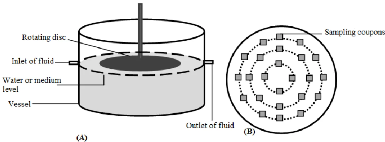
2.5. Rotating Disc Reactor
312
The rotating disc reactor (RDR) consists in a tank with a rotating disc that is submerged in 313
water (Fig. 6). The disc holds several coupons disposed concentrically and, as happens with 314
the CCR, the shear forces depend on the rotational speed and on the diameter where coupons 315
are allocated (Abe et al., 2011, 2012; Pelleïeux et al., 2012). 316
Abe et al. (2011) used this type of reactor to assess the elasticity and physico-chemical 317
properties of DW biofilms in different stages of growth at constant hydrodynamic conditions 318
(hydraulic shear stress of 0.12 Pa and shear rate of 120 s-1). DW biofilms showed a spatially 319
discontinuous and heterogeneous distribution comprising an extensive network of 320
filamentous fungi in which biofilm aggregates were embedded. These results suggest that the 321
DW biofilms were composed of a soft top layer and a basal layer with significant high elastic 322
modulus values, falling in the range of fungal elasticity. The same authors used the RDR to 323
study the cohesiveness and hydrodynamic properties of young DW biofilms (Abe et al., 324
2012). In this study the reactor was operated over three months at shear rates of 120, 175 and 325
230 s-1 (hydraulic shear stress of 0.120, 0.175 and 0.230 Pa, respectively), according to the 326
location radius of each coupon. The results highlighted DW biofilm mechanical behavior 327
depending on cohesiveness strength profile; the increasing of shear stress promoted a layer 328
by layer (stratified structure) biofilm removal; and the detachment shear stress was weakly 329
impacted by the biofilm age (from 4 to 12 weeks) and the hydrodynamic formation conditions 330
(from 0.120 to 0.230 Pa). Pelleïeux et al. (2012) studied the accumulation of phages on DW 331
biofilms at different shear rates (from 450 to 1640 s-1) and under flow/non-flow conditions. 332
All shear rates studied did not cause differences in the levels of virus and bacteria. However, 333
convective diffusion (flow conditions) led to an increase of about 1 log in virus concentration 334
15 on surfaces compared to the levels of the pseudo-steady-state reached during the Brownian 335
diffusion (non-flow conditions). The presence and behavior (survival) of some pathogens (L. 336
pneumophila, P. aeruginosa, Klebsiella pneumoniae and Flavobacterium sp.) in DW 337
biofilms also was studied by Murga et al. (2001) using the RDR with a flow rate at 1 mL.min -338
1(residence time 6.7 h). It was found that, although unable to replicate in the absence of 339
protozoa, L. pneumophila was able to persist in DW biofilms. 340
In RDR, as the entire disc rotates in the water, each radial position experiences a varying 341
hydraulic shear stress, which enables the simultaneous formation of biofilms under different 342
hydrodynamic conditions while keeping all the other conditions constant. 343
344
2.6. CDC biofilm reactor
345
The Centers for Disease Control (CDC) biofilm reactor, also known as CBR, was already 346
used as a DWDS model. In this reactor the coupon holders are supported by a ported lid with 347
each holder containing usually 3 coupons (Fig. 7). The lid with the holders is mounted in a 348
vessel and the agitation is ensured by placing the reactor on a controlled stirrer plate, 349
providing a constant rotation of the baffle (Armbruster et al., 2012; Goeres et al., 2005; 350
Morrow et al., 2008; Park et al., 2012; Park and Hu, 2010). This reactor was used for different 351
applications. Park and Hu (2010) used it to assess the effects of a reverse osmosis water pre-352
treatment on biofilm development in DWDS. However, this pre-treatment was unable to 353
produce biologically stable water, although it had lower growth potential than the tap water 354
produced from conventional water treatment. Armbruster et al. (2012) used a CBR to develop 355
a stable, repeatable, DW multispecies biofilm model (Sphingomonas paucimobilis, 356
Methylobacterium sp., Delftia acidovorans, and Mycobacterium mucogenicum) to 357
investigate the interaction of the opportunistic pathogen M. mucogenicum with other DW 358
16 species, and determined the efficacy of monochloramine as a disinfectant (batch and 359
continuous flow disinfection) against two weeks old biofilms. The reactor operated under 360
batch mode (24 h, 100 rpm) followed by continuous flow conditions (2.5 mL.min-1, 100 rpm, 361
140 min residence time, 13 d). Biofilms persisted in 1 mg.L-1 monochloramine over 24 h but 362
detached bacteria suspended in DW were reduced. Although M. mucogenicum preferentially 363
resided in the biofilm, disinfectant exposure caused release of viable M. mucogenicum from 364
the biofilm into the water. DW biofilms were more tolerant to continuous flow disinfection, 365
which mimicked conditions found in distribution systems more closely than batch 366
disinfection. Morrow et al. (2008) used this device to investigate the impact of fluid shear on 367
Bacillus spores association with biofilm conditioned surfaces in DWDS and the subsequent 368
decontamination with chlorine and monochloramine. Biofilm associated spores required 5- 369
to 10-fold higher disinfectant concentrations to observe the same reduction of viable spores 370
as in suspension. Traditional chemical disinfection with monochloramine and chlorine was 371
an inappropriate strategy for decontamination of Bacillus spores from treated water systems. 372
These authors rationalized the selection of the CDC as DWDS model attending to the 373
possibility to control fluid shear on coupons surface (Morrow et al., 2008; Park and Hu, 374 2010). 375 376 2.7. Microtiter plates 377
The microtiter plates are nowadays the most frequently used reactor system for studying 378
biofilm formation. These can be used as a rapid and simple method to screen simultaneously 379
the effect of high numbers of different parameters on biofilm formation (Simões et al., 2007, 380
2010a, 2011). Simões et al. (2010a) used this device to study the adhesion and biofilm 381
formation on polystyrene by DW isolated bacteria (Acinetobacter calcoaceticus, 382
17 Burkholderia cepacia, Methylobacterium sp., M. mucogenicum, Sphingomonas capsulata 383
and Staphylococcus sp.). The overall results indicate that initial adhesion did not predict the 384
ability of the tested bacteria to form a mature biofilm, suggesting that other events (e.g. 385
phenotypic and genetic switching and the production of EPS) may play a significant role in 386
biofilm formation and differentiation. In other studies, Simões et al. (2007, 2010b) used 387
microtiter plates to assess biofilm interactions between DW isolated bacteria and the 388
influence of bacterial diversity on biofilm resistance to disinfection. In the first study, the 389
results shown that the parameters assessed by planktonic studies (growth rates, motility, 390
production of quorum-sensing inhibitors) did not allow prediction and generalization of the 391
exact mechanism regulating dual-species biofilm formation. Other cell-cell events, such as 392
intergeneric coaggregation, may play a significant role in the formation and interspecies 393
interactions in DW biofilms. Moreover, it was possible to identify synergistic, antagonistic, 394
and neutral interactions between DW bacterial biofilms. The other study allowed to conclude 395
that the bacterial diversity and their interactions may enhance biofilm resistance to 396
disinfection. The same device was also used by Simões et al. (2011) to investigate the effects 397
of metabolite molecules produced by these bacteria on their single and multispecies biofilms. 398
This study allowed the identification of bacterial species which have biocontrol potential (M. 399
mucogenicum) or have a significant role in development and maintenance of the DW 400
consortium (A. calcoaceticus and B. cepacia). These studies proposed that the elucidation of 401
the mechanisms by which diverse species survive and interact in DW biofilm communities 402
may allow the identification of new biofilm control strategies. 403
Gião et al. (2011) used this device to evaluate the interaction of L. pneumophila and 404
Helicobacter pylori with bacterial species isolated from DW biofilms and to study the 405
influence of different autochthonous microorganisms on the incorporation and survival of 406
18 these two pathogens in biofilms. Mycobacterium chelonae (pathogen commonly found in 407
DWDS) seems to have a positive effect on the cultivability of both pathogens and seems to 408
play an important role in the survival and control of these two pathogens in DW biofilms. 409
This work also suggests that the presence of some microorganisms can decrease the 410
cultivability of L. pneumophila but not the viability, which indicates that the presence of 411
autochthonous microorganisms can lead to misleading results when the safety of water is 412
assessed by cultivability-based methods alone. 413
This reactor has the obvious advantage of allowing high-throughput analysis, some of those 414
can be non-invasive using microscopy (Bridier et al., 2013). However, the limitations to 415
reproduce the environmental conditions found in a DWDS are significant. 416
417
2.8. Other bench top devices
418
Other laboratorial devices were developed to allow a better study of DW biofilm formation 419
and control under specific conditions, in order to fill the gap on the limitations of existent 420 reactors. 421 422 2.8.1. Flow chamber 423
The flow chamber is a simple device already used in DW biofilm studies. This allows a direct 424
non-invasive observation of biofilm formation using microscopy. Paris et al. (2007) used four 425
flow chambers fed in parallel with tap water and coupled to an inverted microscope to study 426
the effects of different shear rates (34.9, 74.8, 142.5 and 194.5 s-1) on biofilm development 427
and structure. During the first stage of biofilm formation, bacterial accumulation was a 428
function of the wall shear rate: the higher the wall shear rate, the faster the bacterial 429
deposition. After 50 days, surface coverage was more or less identical for all wall shear rates, 430
19 suggesting that biofilm bacterial density cannot be controlled using hydrodynamics. 431
However, the spatial distribution of the biofilm was clearly different. Under low wall shear 432
rate, aggregates were composed of bacterial cells able to ‘‘vibrate’’ independently on the 433
surface, whereas, under a high wall shear rate, aggregates were more cohesive. The same 434
authors (Paris et al., 2009) used the same experimental setup described in the previous study 435
with DW biofilms. The authors examined biofilms with two model particles recognized as 436
hard (polystyrene) and soft particles (E. coli) in order to investigate the distribution and 437
persistence of these allochthonous particles inoculated in DW flow chambers at various wall 438
shear rates (70 to 460 s-1) in biofilms with different ages (from 6 to 10 months old). The study 439
showed that biofilm age (e.g. bacterial biofilm density and properties) and convective-440
diffusion governed the particle accumulation: older biofilms and higher wall shear rates both 441
increased the velocity and the amount of particle deposition on the DW biofilm. 442
443
2.8.2. Reactors with glass beads 444
Bauman et al. (2009) described another device, a reactor containing glass beads, where the 445
DW biofilms were developed and their ability to retain E. coli was analyzed. The study 446
concluded that this engineered biofilm systems may be considered as a relevant device to 447
capture pathogens from the bulk flow for monitoring purposes. So, it can contribute to 448
improve the general insights into interactions between pathogens and DW biofilms. Codony 449
et al. (2005) and Morato et al. (2005) used a packed-bed biofilm reactor filled with glass 450
beads to monitor DW biofilm development by removing the biofilm attached to these beads 451
for off-line analysis. Lehtola et al. (2002) used a PVC chamber covered with aluminum foil 452
containing PVC slides to study the effects of low concentration of phosphorus in biofilm 453
20 development. The results showed that the availability of phosphorus regulated not only the 454
development rate of biofilms but also microbial numbers during steady-state. 455
456
2.8.3. Chemostat 457
A two-stage chemostat model system was used to evaluate the persistence of H. pylori in DW 458
biofilms (Gião et al., 2008). For biofilm formation, the chemostats were fed with filter-459
sterilized tap water at 50 mL.h-1. These vessels contained PVC coupons used to sample the 460
biofilm overtime. The influence of three parameters (low carbon concentrations, shear stress 461
and temperature) on the persistence and cultivability of H. pylori in DW biofilms was studied. 462
The results shown that shear stress did not influence negatively the numbers of H. pylori cells 463
attached, suggesting that the autochthonous DW bacteria have an important role in retaining 464
this pathogen in the sessile community. 465
Teng et al. (2008) used a simple system where coupons were submerged in a glass bottle fed 466
with tap water. The cast iron coupons were removed at different times and after each sample 467
the water was displaced with new tap water or sterile tap water to simulate the intermittent 468
water flow environment in pipes. The aim of the study was to assess the effects of biofilms 469
on cast iron pipe corrosion over time in DWDS, namely the characterization of corrosion 470
scales and DW biofilm community structure. The authors demonstrated that the biofilm can 471
greatly affect element composition and crystalline phase of corrosion scales. Also, biofilms 472
accelerated corrosion in the first 7 d, but inhibited corrosion thereafter, which was due to the 473
changes in the biofilm microbial diversity (presence of iron bacteria and iron reducing 474
bacteria). 475
van der Kooij et al. (1995) designed a device based on two principles: the hydraulic 476
conditions should resemble those in pipes of real systems, and should have a simple 477
21 construction and use. The device consisted in a vertically placed glass column, containing 40 478
glass or Teflon cylinders for cell adhesion. The water flowed downward through the column 479
(4.6 L.min-1, 0.2 m.s-1) coming in contact with the inner and the outer surface of the cylinders. 480
With this system, the authors assessed the effects of support material, water type and nutrients 481
on the rate and extent of biomass accumulation. The results showed that the material type 482
(glass and Teflon) and the cylinder position had minor or insignificant effects on biomass 483
accumulation. On the other hand, biofilm formation was strongly enhanced by low 484
concentrations of easily available substrates, such as acetate. 485
486
2.8.4. Glass ring column 487
A glass ring column device, similar to the flow cell system, was used to assess the influence 488
of biofilms on Fe and Mn deposition in DWDS (Ginige et al., 2011). The column was feed 489
with tap water inoculated with DW microorganisms, namely Pseudomonas fluorescens and 490
Spirillum spp. The reactor was allowed to operate continuously for 4.5 months at a flow rate 491
of 0.42 mL.min-1 anda recirculation rate of 667, the reactor resembled a completely mixed 492
flow-through configuration. This study addressed the contribution of biofilms to discoloured 493
water incidents. Biofilms facilitated the deposition of Fe and Mn on pipe walls, an increase 494
in biofilm activity was associated with an increase in Fe and Mn accumulation. So, reducing 495
biofilm accumulation should be considered along with other strategies, such as removal of 496
Fe and Mn via water treatment to better manage discoloured water events. 497
498
2.8.5. Pedersen device 499
The Pedersen device is used coupled to other bench top devices, as flow cells, and it was 500
used to study biofilms in flowing-water systems (Pedersen, 1982). To build this device, 501
22 microscope cover slips were fitted into acrylic plastic holders forming two parallel test piles, 502
each with room for 19 slips. The test piles were placed in flow cells, and in order to separate 503
the flow at the inlet of the reactor three diffusers with different hole patterns were used. These 504
diffusers were located in both sides of the reactor, being possible to change the flow direction. 505
Flow stabilizers, which were identical to test piles, were used to establish a laminar flow 506
between the slips. The sampling process in this device was done at fixed times taking out a 507
desired number of slips for off-line analysis. Normally, one sample consisted of two slips, 508
one from each of the two parallel piles. The sampled slips were replaced with new ones in 509
order to maintain the flow conditions (Pedersen, 1982). 510
511
2.8.6. Loop with biofilm test-plug module 512
Boe-Hansen et al. (2003) developed a loop with biofilm test-plug module in order to simulate 513
DWDS conditions and to produce a large number of biofilm samples grown under 514
comparable conditions. This device was constituted by two identical loops connected in 515
series and in each loop there was an adjustable centrifugal pump to recycle the water. The 516
recycle-flow rate was controlled by a needle valve installed immediately downstream the 517
pump. Both loops contained two strings of biofilm test-plug modules made from square 518
pipes, each string consisted of a row of 5 biofilm test-plug modules, each with 7 test-plugs. 519
To prevent turbulence induced by pumps, valves and bends and to stabilize the flow inside 520
the modules, a 2 m square pipe was inserted just upstream of the test plug modules. This 521
construction should guarantee that the velocity distribution was identical from cross-section 522
to cross-section, and that all test plugs within a loop were exposed to identical hydraulic 523
conditions. Using this device, Boe-Hansen et al. (2003) monitored biofilm formation and 524
activity in DWDS under oligotrophic conditions. The purpose of this study was to test 11 525
23 different microbial methods for monitoring biofilm in DW, at low nutrient conditions. The 526
methods used allowed biofilm characterization in terms of biomass quantification, metabolic 527
activity measurement, structure visualization and microbial diversity profiling. The model 528
distribution system was continuously fed with DW from a municipal distribution network 529
(retention time 2 h, flow velocity 0.07 m.s-1). The model distribution system and the biofilm 530
sampling modules used in this study provided an easy access to a large number of biofilm 531
samples. The system allowed biofilms to be grown under controlled conditions comparable 532
to those prevalent in the DWDS. The retention time, the flow rate and temperature were 533
independently controlled in the system, and furthermore it allowed chemicals or specific 534
microorganisms to be added. 535
536
3. In situ application devices
537
The in situ devices were developed to study and monitor DW biofilms in pilot and real 538
DWDS. These devices are usually placed as a by-pass or directly connected to a DWDS. 539
540
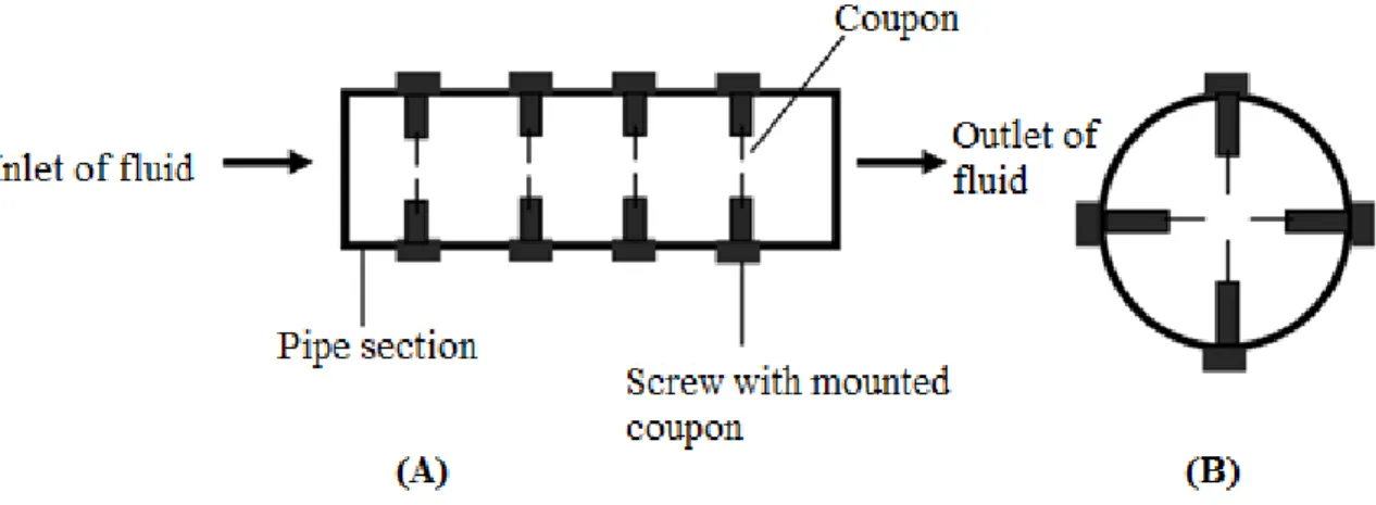
3.1. Robbins device
541
The Robbins device is one of the mostly used to study biofilm behavior in situ in real and 542
pilot scale DWDS. The Robbins device is a pipe with several threaded holes (Fig. 8). Some 543
screws with coupons mounted on the front side are placed in these holes (Manz et al., 1993; 544
Sly et al., 1990). The coupons are aligned parallel to the water flow and can be removed 545
independently (Manz et al., 1993). 546
As referred previously, the Robbins device can be applied directly to real DWDS. Sly et al. 547
(1990) studied the manganese deposition in a DWDS in the Gold Coast (Australia). The 548
results showed that manganese (bulk concentration of 0.05 mg.L-1) deposition occurred by 549
24 chemical and microbial action, although the chemical deposition rate was much higher than 550
microbial deposition. Manz et al. (1993) also used the Robbins device to test biofilm 551
formation on glass slides in the Norrvatten (Sweden) DWDS at a distance of 30 km from the 552
waterworks. These authors found that surface-attached cells are more active than free-living 553
equivalents. Also, the authors found that microcolonies in very early stages of development 554
consisted of mixed populations. 555
As the Robbins device is responsible for significant changes of the water flow on the slides, 556
several authors developed a modified Robbins device (MRD). Nickel et al. (1985) developed 557
a MRD to assess the degree of resistance of biofilm bacteria to antibiotics in catheter material. 558
This new device consisted in a pipe with 25 spaced sampling ports attached to sampling plugs 559
flushed with the inner surface, without disturbing the flow characteristics. Kalmbach et al. 560
(1997) used the MDR in a DWDS of Berlin (Germany) with a flow rate near of 6 L.h-1 to 561
investigate the metabolic activity and the phylogenetic affiliation of single adherent bacteria 562
during colonization and biofilm formation in DW. The authors found that respiratory activity 563
of adherent bacteria decreased continuously during the early stages of biofilm formation. 564
Carter et al. (2000) used this device in the Milford (USA) DWDS using a flow rate near of 565
0.4 L.min-1. The main goal of this study was to identify relationships among heterotrophic 566
bacteria and standard physical and chemical water quality parameters. A relationship was 567
found particularly to cultivability counts on R2A medium. Silvestry-Rodriguez et al. (2008) 568
also used this device to study biofilm control in an experimental plant using water from 569
Tucson (USA) DWDS, operating at 0.4 L.h-1. PVC and stainless steel were used as biofilm 570
formation substrate, however, no significant inactivation was observed on both surfaces 571
when treated with silver at 100 µg.L-1. 572
25 Latter, Kerr et al. (2000) developed the newly modified Robbins device (nMRD) that 573
consisted in a MRD adapted to form two separate halves, being possible to take it apart and 574
to clean it. This new device was constructed from Perspex and the two separate halves were 575
held together by thirty screws, and the whole device had Perspex connectors at both ends to 576
which the tubes were attached. This study was performed in order to investigate the 577
reproducibility of attachment and whether there was a statistical significant gradient of 578
adhesion along the 25 sampling ports of the nMRD. No significant difference occurred 579
between pairs of nMRDs that were run in parallel, however, there was a significant difference 580
between different batches of bacteria. It also was observed that the position of the sample 581
disc influenced bacterial adhesion. Other variation of the Robbins device was presented by 582
Jass et al. (1995) that used a chemostat-coupled MRD. The association of a chemostat and a 583
MRD provides a large number of sample surfaces for monitoring biofilm formation and 584
control over extended periods of time. These authors proposed that this device can be 585
successfully used for studying bacterial adhesion and biofilm formation in tubular devices. 586
587
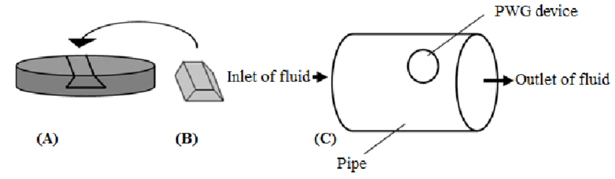
3.2. Pennine Water Group coupon
588
Recently, it was developed a new coupon sampling device for in situ studies, the Pennine 589
Water Group (PWG). This coupon can be inserted directly into the pipes of DWDS, 590
maintaining flow conditions representative these near wall pipe and enabling simultaneous 591
quantitative and qualitative compositional characterization of in situ biofilms (Deines et al., 592
2010). This offers improvements over alternative sampling devices and the coupons are 593
comprised of two parts, an “outer coupon” and an “insert” (Fig. 9). The outer coupon retains 594
the curvature of the pipe and fits precisely into a hole made in a removable and flanged 595
identical pipe section. The coupon is fixed with a gasket to a section pipe. The insert is 596
26 engineered flat to allow microscopic analysis and it fits inside of the outer coupon in a way 597
to allow the outer surface to be in direct contact with the water. This design has a maximum 598
deviation from curvature of 0.064 mm, in the order of magnitude of the surface roughness 599
coefficient used in hydraulic models (Deines et al., 2010). It is an accurate device and allows 600
direct insertion and close alignment with the internal pipe surface, minimizing the distortion 601
of boundary layer conditions that influence biofilm formation, such as boundary shear stress 602
and turbulent driven exchange with the bulk water body (Douterelo et al., 2013). This coupon 603
was used in a full-scale laboratory pipe loop. Deines et al. (2010) used a constant flow rate 604
of 0.4 L.s-1 (boundary shear stress of 0.03 N.m-2) and it was observed an increase in bacterial 605
biofilm coverage of the coupon surface over time, as well as, the development of increasingly 606
complex biofilm communities. Douterelo et al. (2013) used PWG coupons to evaluate the 607
effect of different and variable flow rates (0.2 to 0.5 L.s-1; 0.2 to 0.8 L.s-1 and 0.4 L.s-1) on 608
biofilm development and detachment from pipe walls. They concluded that different 609
hydraulic regimes affect the composition and diversity of bacterial communities in biofilms. 610
However, the use of increasing flow rates did not completely remove bacteria from pipe 611 walls. 612 613 3.3. Bioprobe monitor 614
The bioprobe monitor was specifically designed to study biofilm growth within a pipe 615
system. LeChevallier et al. (1998) described a pilot-scale DWDS (1.3 km) that had an 616
experimental test station with 24 m and contained three test sections. A bioprobe monitor 617
was located at the beginning of each experimental section to monitor the environmental 618
conditions and biofilm development. The bioprobe monitor consists of a pipe where it is 619
inserted a coupon holder (denominated acetal) being the coupon surface flushed with the pipe 620
27 wall (Fig. 10). LeChevallier et al. (1998) also used this device to study the effects of chlorine 621
and monochlorine on biofilm development at a water flow rate of 0.07 L.s-1. These authors 622
observed that the density of bacteria on the iron surfaces reached a maximum when the 623
temperatures were higher and when there was a total declination of chlorine residuals. Also, 624
they observed lower cell densities in the first section of the pilot-scale DWDS and this was 625
due to the fact that more chlorine reached this part of the system. 626
627
3.4. Other in situ devices
628
Other devices were used for in situ DW biofilm studies. Juhna et al. (2007) used a biofilm 629
sampler that consists in a coupon holder inside of a pipe section. The authors used a total of 630
22 holders exposed to DW in a DWDS from Latvia and France to detect E. coli. This 631
bacterium was found in 56% of the coupons using peptide nucleic acid fluorescent in situ 632
hybridization (PNA-FISH), however, it was not detected using culture-based or enzymatic 633
methods. The presence and amount of E. coli detected was not correlated with any physical 634
and/or chemical characteristics of DW such as the temperature, chlorine or biodegradable 635
organic matter (BOM) concentration. Helmi et al. (2010) used a pilot device constituted by 636
5 PVC compartments comprising a holder with six removable discs allowing the study of the 637
effects of different surface materials on biofilm development. The device was connected to 638
the tap of a DWDS operating at a flow rate of 2 L.min-1 in order to study the interaction 639
between virus and DW biofilms and to develop a method to detect viral particles in these 640
biofilms. Five protocols were used for viral recovery, testing different sonication intensities 641
(20% and 40% power intensity) and its combination with centrifugation (1500 g for 10 min) 642
and with pH neutralization. The most efficient protocol, that combined all the steps, allowed 643
a recovery rate from 29.3% to 74.6% depending on the virus and on the material. The study 644
28 of viral interactions with DW biofilms allowed to conclude that viral adsorption to biofilms 645
depends on their isoelectric point, the disc material and the hydrodynamic conditions. For 646
example, the viral adsorption to biofilms is less than 1% of the initial viral load when 647
hydrodynamic conditions similar to those existing in DWDS were applied. Prévost et al. 648
(1998) developed a study using a biofilm coupon device, known as the Prévost device. This 649
device was installed on two DWDS of the city of Laval (Canada) and was used to remove 650
the biofilm samples from the DWDS. The authors installed diverse devices in valve chambers 651
and investigated the impact of nutrients levels and oxidant residual maintenance in the 652
biofilms formed in the DWDS. They found that a low nutrient concentration reduced 653
bacterial biomass. Nevertheless, the most significant differences were only observed in warm 654
water and not in cold water. 655
Another device is the sliding coupon holder, a pilot-scale device (Chang et al., 2003). This 656
device is a half PVC pipe where coupons are located, being easily removed and replaced after 657
each experimental phase. Chang et al. (2003) used this device to determine the effects of 658
blending different water qualities on the final quality of the water in the distribution system. 659
The biofilm density was estimated on different pipe materials using a specific DNA-probe 660
(BO-PROTM 3). They concluded that this technique provided results that were correlated to 661
these obtained from heterotrophic plate counts on R2A medium, after biofilm scrapping. 662
Therefore, the technique used allowed to quantify fixed biomass without disrupting the 663
biofilm. 664
Långmark et al. (2005) investigated the accumulation and fate of a model microbial pathogen 665
in natural grown biofilms formed in a pilot-scale DWDS provided with chlorinated and UV-666
treated water. Two pilot-scale DWDS were used, comprising 1 km of polyethylene tubing 667
that was connected directly to the finished water. The biofilm sample devices were chambers 668
29 equipped with 20 exchangeable glass slides and were located at various distances along each 669
DWDS pilot scale, corresponding to different residence times (0.1, 15, 40 and 110 h) within 670
the main Stockholm DWDS. It was not found a significant impact of primary disinfection 671
processes on the accumulation and fate of pathogen models (L. pneumophila and 672
bacteriophages) within the DWDS. 673
Other devices were constructed to study microfungal behavior in DWDS. Sammon et al. 674
(2011) investigated the microfungi colonization of hard surfaces within the storage and 675
distribution system by suspending artificial coupons within the water body of reservoirs. 676
Sammon et al. (2011) used glass, PVC and concrete coupons held in sets of custom-made 677
racks. These racks were designed to held one coupon vertical and apart from the other 678
coupons, to ensure a free flow of water across both surfaces of all coupons. The racks were 679
placed in lidded plastic basket which was perforated on all sides, bottom and top. The basket 680
was attached to nylon ropes and a clay house brick was used to held the basket at 1.5 m from 681
the bottom. This work allowed to conclude that airborne spores introduced into reservoirs 682
can be an important external source of microfungal propagules, however, it was also observed 683
that the microfungi were not involved in the primary colonization of surfaces. The results 684
also suggested that any aggregation of soft sediment in the DWDS was a potential site for 685
the proliferation of the microfungal population. Siqueira et al. (2011, 2013) proposed the use 686
of a distinct device to investigate natural filamentous fungi biofilms in DWDS, the sampler 687
device. The core of the sampler device consists of hollow PVC pipes with polyethylene or 688
acetate coupons held in place to allow biofilm growth. The end of each sampler forms a screw 689
to connect multiple samplers or to close the device with a cap after coupon removal from the 690
water network. These features facilitated insertion, handling and removal of each sampler 691
device after collection and preventing contact with external environment during the transport 692
30 process. Finally, the pipes could be filled with water in order to maintain moisture and 693
preserve the integrity of the biofilms formed on the coupons. Siqueira et al. (2013) used this 694
device in a DWDS at Recife (Brazil), concluding that this device is useful to study DW 695
biofilms and that Calcofluor White (CW) staining is a rapid and efficient method to detect 696
filamentous fungi, allowing its differentiation by morphology. This study also demonstrated 697
that fungi are likely to play an important role in DWDS biofilms and final water quality. 698
699
The main advantages and limitations of the main devices described previously are 700
synthesized in Table 2. These are mostly related with the ability to study and control the 701
hydrodynamic conditions, with the sampling process, the temperature control, the possibility 702
to use different surface material, and the possibility to operate under conditions similar to the 703
real systems. 704
705
4. Main applications of reactors in DW biofilms studies
706
In general, the main applications of several described reactors in studies of DW biofilms are 707
monitoring the biofilm formation with different operational conditions (support material, 708
hydrodynamics, temperature, nutrients, type of microorganisms, disinfectants) and biofilm 709
control by different strategies (process conditions and disinfection). Table 3 synthesizes some 710
of the studies on DW biofilms using reactors, making reference to the main process 711
conditions and microorganisms used. 712
713
4.1. Biofilm control
714
Several strategies can be used to attempt biofilm prevention and control in DWDS. The pre-715
treatment of water, before being released into the DWDS is an important preventive measure 716
31 and usually consists in the minimization of the organic matter and nutrients concentration 717
entering the distribution system. The material selection to apply in the DWDS pipes and 718
fittings is also important to control biofilm development. The use of antimicrobial 719
compounds is common, being important to maintain a residual concentration of disinfectant 720
inside the DWDS. Simões and Simões (2013) described usual and new techniques used to 721
prevent and control biofilm formation in DW. Nonetheless, biofilm control by manipulating 722
the operation conditions (temperature, flow rate and shear stress, presence of nutrients, 723
material selection) is also a matter of study (Ndiongue et al., 2005; Rickard et al., 2004; 724
Simões et al., 2006; Torvinen et al., 2007). 725
726
4.1.1. Management of operational conditions 727
To control biofilm development it is important to understand how its development happens 728
and the role played by the operational conditions (Douterelo et al., 2013; Lehtola et al., 2007; 729
Pintar and Slawson, 2003; Simões et al., 2006; Torvinen et al., 2007; Volk and LeChevallier, 730
1999). Ollos et al. (2003) evaluated the influence of several factors (BOM concentration, 731
monochloramine and chlorine disinfection, flow velocity, pipe material and temperature) on 732
biofilm development using as DWDS model an annular reactor. Under the conditions studied, 733
the disinfectant residual was the most important factor for biofilm accumulation. In the 734
absence of BOM, temperature seemed to have no effect, whereas shear stress seemed to be 735
important. In the presence of BOM, temperature was important at low shear stress, although 736
shear stress conditions themselves had little effect. The condition leading to the strongest 737
biofilm accumulation was a high level of BOM combined with the absence of a disinfectant. 738
The temperature effect was studied by Ndiongue et al. (2005) and Pintar and Slawson (2003) 739
using an annular reactor, as previously referred. Torvinen et al. (2007), as already said, used 740
32 a Propella® reactor to assess the effects of different temperatures on biofilm growth, but also 741
studied the influence of flow velocity and phosphorous concentration. 742
The effect of hydrodynamic conditions was investigated in biofilm growth using diverse 743
reactors. The flow cell system is one of the systems used to achieve this goal (Manuel et al., 744
2010; Simões et al., 2006), as well as the Propella® reactor (Lehtola et al., 2007). CCR and 745
RDR allowed the evaluation of the effect of different shear stresses on biofilm development 746
(Abe et al., 2012; Rickard et al., 2004). The in situ devices also can be used to study the 747
hydrodynamic effects on biofilm development, simulating a flushing situation, as did by 748
Douterelo et al. (2013) using the PWG coupon, as previously referred. 749
Another important aspect that can help to control biofilm development is the type of surface 750
material. The annular reactor was expressively used with this aim. Zhou et al. (2009) used 751
this device to study the effects of surface material (SS and copper - Cu) on disinfection by 752
chlorine and chloramines. The results showed that biofilm formation was affected either by 753
the type of disinfectant as well as by the type of pipe material. Chloramines were more 754
effective than chlorine in controlling biofilms formed on both SS and Cu surfaces. The tested 755
pipe materials did affect bacterial accumulation when chlorine and chloramines were present. 756
There were fewer bacteria attached to Cu slides with chloramines or chlorine disinfection 757
when compared with SS. The combination of Cu pipes and chloramines as the disinfectant 758
was the most efficient combination to get low biofilm accumulation. Jang et al. (2011) did a 759
similar study comparing the influence of steel, SS, Cu and PVC on biofilm formation and 760
water quality. An annular reactor with coupons of these materials was operated under 761
hydraulic conditions similar to a real plumbing system (50 rpm, 0.25 N.m-2, approx. 0.3 ms -762
1), at a flow rate of 170 mL.min-1 for 15 months. The results showed that biofilm formation 763
and water quality were substantially affected by the pipe materials. The bacterial 764