SPATIUM International Review UDC 624.012.46.059.3 No. 32, December 2014, pp. 1-6 Original scientific paper DOI: 10.2298/SPAT1432001S
GLULAM BEAMS REINFORCED WITH FRP STRIPS
AND THEIR APPLICATION IN ARCHITECTURE
Radivoj Solarov
1, TS ’Mileva Marić – Ajnštajn’, Novi Sad, Serbia
Milan Gliši
ć
, University of Belgrade, Faculty of Architecture, Belgrade, SerbiaThis paper emphasizes the advantage of using carbon polymers while producing and strengthening glulam beams. Due to advanced research carried out in this field, the first application of carbon polymers based products was implemented in Western countries. Structural elements containing carbon polymers, or being reinforced by them, show higher resistance and durability properties, as well as the ability to be produced in various shapes. These features can find best application in architecture so the architects’ imagination in design could be realized. Many attractive buildings were constructed over the last decade, each of them showing exceptional safety, resistance to atmospheric influences, durability and cost-efficiency. Beside application of carbon polymers in the construction of new buildings, they are even more important in the field of historic heritage restoration. The original research carried out on ten samples in the laboratory is presented in the second part of the paper. Position of the reinforcement on the samples was chosen as it would be done in practical retrofit cases. Deformations of the samples exposed to pure bending were measured, so their behaviour in the elastic range could be analysed based on the results. Measured results were compared to those calculated by using FEM model, developed with software package AxisVM. Based on performed analysis, the conclusion was made that by strengthening timber glulam beams with FRP strips, the simple and efficient static load bearing capacity upgrade is gained.
Key words: FRP strips, glulam strengthening, architectural structures, testing samples, FEM model.
INTRODUCTION
1It was in the 1960s when two new epochal products emerged in the chemical industry, which found wide use in all areas of life. Firstly there were strips consisting of carbon fibres (CFRP), and beside them, adhesive epoxy resins (ER). Originally they were used in the military industry for weapon production: fighter jets, remote-controlled aircrafts, ships, automatic weapons, bulletproof wests, etc. Furthermore, these materials found wider purpose in the car industry for the production of race car bodies, as well as safety cabins which protect the driver due to high impact resistance, even at speed of 150mi/h. It might be interesting to mention that certain products were modified in order to get more elegant and stronger ones: tennis racquets, golf clubs and fishing rods, wind power plants propellers, generator blades, strips for heavy lifting, sport protective equipment, etc. Modern composite materials production technology basically uses
1Gagarinova 1, 21000 Novi Sad, Serbia
numerous thin fibres made of carbon polymers. This enables production of very durable materials. Solid beams, square cross-section, rectangular, circular or jagged shapes could be formed by twisting (pultration) from carbon fibres CFRP (Carbon Fibre Reinforcement Polymer) that are only 5-10 μm thick. Most often the cross-sections of the load-bearing structures are formed as composites from traditional materials (timber, steel or reinforced concrete), strengthened by carbon materials in the shape of rod, strip or panel, in the major stress zone. Content of carbon fibres in standard strips is approximately 50% of the volume, or 70% of the total mass, while the rest are fillers and epoxy resin used to connect fibres. If we compare carbon fibre strips characteristics with steel bars, with same cross-section areas, we come to see that carbon strips tensile load bearing capacity is 6 to 8 times higher, while the weight is 75 to 80% less than steel, and 30% less than aluminium.
Another product of modern technology that makes reinforcement possible is a high quality adhesive that creates a good bond between the
surface of the beam that is being strengthened and composite reinforcement. This multi-component glue contains epoxy resin as the main component. Adhesive strengthening does not take much time and a good bond of high endurance to shear, so good elastic properties between the elements are quickly achieved. Bond quality is reached if the reinforced element surface is compact and if the pull-off test shows required strength.
IMPLEMENTATION OF FRP
PRODUCTS IN ARCHITECTURE
From the point of view of architecture, the main advantage of using FRP materials is that in conjunction with other building materials, load-bearing capacity can be increased only in points where needed, reducing the height of the structural element, and therefore the weight. These characteristics have given the opportunity to architects to express their creativity in designing and implementing them in constructing objects that were, until then, almost impossible to be realized.
Aesthetic appeal of the object is of main importance even for the large span construction elements. Composite elements fully satisfy other requirements made by modern society, such as energy efficiency of buildings, environmental impact, resistance to aggressive environment and moisture. Architecture of constructing timber structures is improved by using composite materials, especially in those countries with great economic growth. This will be illustrated through several examples that have been realized in the last fifteen years.
The Road bridge Tynset
The bridge consists of three arches, with the largest span of 70m, in a shape of lattice girder, with two smaller glulam arches, 26.5m in span each. Total length of the bridge is 124m. It has elegant appearance despite being exposed to dynamic effects and vibration due to heavy traffic and earthquakes. Therefore the suspended road slab was made of glulam beams and reinforced concrete slabs, prestressed with steel cables. Specific attention is paid to protect structure from moisture, and it is stabilized at 10%. In order to achieve this, elements made of impregnated pine were covered with copper along the top surface, while the road slab was protected with waterproof membrane. In addition, the bridge is cost-efficient considering building and maintenance.
Church structures –The Cathedral in Oakland
Church objects demand special conditions when it comes to size, aesthetics and acoustics. This can be achieved by using glulam curved beams, arches and lattices. Such unique structure was built as the temple of the Holy Saints of Christ in Oakland. It was constructed from two curved glulam and steel frames forming walls. Frames are circular, intersecting with each other, forming a shape of football stadium. The inner circle is 100m in diameter, while the outer one is 103m. The structure was designed with seismic resistance to return period of 1,000 years earthquake.
The LeMay Car Museum
The largest car museum was designed to demonstrate the love of a society which is the largest car manufacturer in the world. It was decided to use glulam not for aesthetics purposes only, but to achieve lower construction cost, due to limitations in the budget. The construction of the LeMay museum cost approx. $1,120 per m2, while the
typical museum cost varies between $4,500 and 9,000 per m2.
When entering the exhibition hall, beside the line of sparkling classic cars, visitors can see the roof system with curved laminated beams. The frame span is 104m. It is strengthened with FRP strips in corners. In general, it is one of the biggest framed structures in the world. Fire resistance of this structure is 1 hour, and it also meets the specific requirements set forth by the National Earthquake Hazards Reduction Program. The roof cover, which is curved at the corners with a radius of 17m, is very impressive. It consists of shiny metal sheets, like aero-dynamic surface of a car. The structure offers a distinct sense of grandeur and aesthetic perfection of vast space.
Nowadays, other composite materials such as: self-compacting concrete for filling precast joints (Okrajnov-Bajić, 2009), and fiberglass waterproof cloth membranes for covering domes (Vavan-Vučeljić, 2009, Nenadović, 2010) are being used for raising this type of objects.
FRP strengthening methods for existing buildings
In comparison to above mentioned buildings, there is much larger number of existing objects in need of static strengthening, due to changes in function. This occurs in cases when new, additional load is to be applied to the girder, when it needs to be transferred to another static system, or if the existing system is deformed, and needs to be retrofitted. The procedure of reinforcing glulam elements is very simple and gives excellent results shortly. It can be applied successfully when repairing timber elements in old buildings representing protected historic monuments, or in the buildings with changed room function. Strengthening of domes, towers, chimneys and silos is performed in a similar manner, by circular wrapping with FRP strips, so critical stress zones are covered.
FRP is perfectly flexible material which can be adjusted to a circular shape, fits well to the surface and the ring can be accomplished by overlapping the ends over each other. Reinforcement has a primary role in stiffening spatial structure by accepting unintended horizontal shear forces which may occur unexpectedly during earthquakes. The technique of strengthening with carbon FRP strips enables constructing buildings resistant to seismic impacts or restoring buildings damaged by the earthquake. Considered cases of strengthening structures have justified application when upgrading the building and strengthening protected cultural monuments. Due to high demands that must be met in the Figure 2. The Cathedral of Christ the Light, in Oakland,
California, USA (2008).
Source: http://upload.wikimedia.org/wikipedia/commons/ thumb/f/f4/Oak_Cathdrl_1.jpg/250px-ak_Cathdrl_1.jpg
Figure 3. The LeMay Car Museum in the city of Tahoma, USA (2012).
Source: http://www.tripadvisor.com/Attraction_Review-
g58775-d3203900-Reviews- LeMay_America_s_Car_Museum-Tacoma_Washington.html, or http://media-cdn.tripadvisor.com:
/media/photo-t/02/88/27/bb/lemay-museum-at-marymount.jpg
http//www.go-explore-trans.org/wp-strengthening approach, quality testing of the materials from which the element was made is recommended, as well as assessment of its condition. Based on these results, it is possible to make the best choice for retrofit project. For these purposes, it is recommended to develop numerical model for analysing limit stress state in the model.
Carbon fibres are durable and do not lose their mechanical properties over time. Their exploitation period is more than 50 years. However, despite the time resistance, it is necessary to check their load bearing capacity periodically and, if necessary, renew protection or replace them.
Having high compressive strength, being lightweight and resistant to corrosion, it can be concluded that, when it comes to strengthening elements, FRP strips are superior to high-performance steel intended for prestressing concrete.
PROPERTIES OF REINFORCED
GLULAM BEAMS
Additional important glulam beam properties will be highlighted in this part of the paper. When comparing the strengths of wooden beams, it can be noticed that solid timber has lowest strength due to inhomogeneity of the material or due to orientation of the fibres in single direction only (Figure 4). When it comes to glulam elements, timber fibres are arranged in layers in the same direction, so the beam has greater strength. If such beam is strengthened with FRP strips, even larger strength is achieved.
It is important to notice that solid timber beams show largest dispersion of results, due to greater possibility of occurrence of defects in the material. These faults are leading to the fracture.
When it comes to choosing strengthening reinforcement we can make a comparison of all known materials with the same cross-section surface areas, using operating stress/strain diagrams. Carbon fibres have highest strength and stiffness of all fibres used in structural and homogenous strengthening materials. Carbon FRP strips are divided into several categories based on the modulus of elasticity.
Environmental impact is of great importance in the selection of suitable materials for construction process, as well.
In this respect the glulam beam is biodegradable with the possibility of being recycled, i.e. production of glulam beams requires about two times more energy than the energy needed for production of the solid timber beams. FRP strips are also made of material that can be recycled.
Fire resistance is significantly better when compared to steel, since timber conducts heat 300-400 times slower than steel. Timber element exposed to fire creates a carbonaceous layer on the surface, so the heat transfers to the inner parts of the cross section at a speed of 0.6 to 1.1mm/min. At such temperatures beam does not deform, does not apply additional pressure on the supports and does not collapse (Kuzman, 2010).
In recent years, experiments were carried out on sample beams exposed to gas flame at 800°C. After being exposed to fire, samples reinforced with FRP strips retained their form and load bearing capacity as opposed to the non-reinforced samples that have undergone major changes. It is believed that strengthened surfaces of the beams suffered less because of the FRP strips blocking the flow of oxygen to the timber. This means that FRP strengthened glulam beams can withstand the fire for 1 hour, which is long enough to evacuate the people from the building in case of fire emergency (Ogawa, 2000).
The energy efficiency of timber and carbon is reflected in the fact that they are both good heat and sound insulators. Even though a large amount of carbon-dioxide is being released in the process of burning these materials, this harmful gas is absorbed by increasing the forest areas. For this reason, afforestation is important for environmental preservation. Production and processing of timber creates the conditions for increasing its use in buildings construction. Such goal can be achieved by developing a National plan for the conservation of wood resources and the environment in the upcoming century, like the one being implemented in Japan (Ogawa, 2000).
From ecological point of view, as a housing space consumer one must follow bio-climatic principles and have a responsible approach towards the environment he is part of. Keeping this in mind he should tend to choosing transparent facades as well as natural and simple materials, in order to achieve the effect of presence of surrounding inside of the object (Kosorić, 2011, Bajić, 2011).
LABORATORY STUDIES
The first study which will be presented in this paper began in 2006. FRP reinforcement strips were applied to laminated wooden beams, which were later experimentally tested (Solarov et al. 2011). The aim of the research was to study the behaviour of glulam timber beams-samples exposed to short-term bending load. Based on the measured values of deflection and strain at characteristic points of the samples, the effect of reinforcement can be analysed, comparing the deformation of the non-reinforced and non-reinforced samples. Along with the laboratory testing, calculation of impact on numerical model was carried out as well.
Previous examinations
These tests were conducted in order to determine the actual mechanical properties of the materials that can be used for the development of computational models, and the selection of equipment for loading and measuring deformations on the samples. For this purpose, several preliminary tests were conducted in order to collect data:
The first testing showed whether it was possible to strengthen glulam elements with FRP strips. They transmit large forces, so it is necessary for timber surface to be resistant to tension (pulling). ’Pull off’ method was used for this purpose. Three measurements were made with this equipment. Each measurement gave results that were higher than the min. values for the substrate of 1.5 N/mm2. This
way, it was concluded that the surface was able to undertake strengthening.
The second test was related to the determination of the quality of the adhesive connecting the timber slats, or to determination of shear forces that can be accommodated by the compound. The tests were carried out on three samples composed of glued lamellas. The procedure was performed by the device for applying vertical forces, and fracture in all cases occurred at a wooden lamella at forces between 24.40 and 25.0kN.
The third test was performed in order to Figure 4. Average compressive strength in the cross-section
determine the quality of adhesives used for bonding FRP strips and timber lamellas. FRP strip was glued between two timber lamellas with epoxy glue Sikadur-30. The load was applied gradually using the same device as in the previous experiment; however, the fracture appeared in the timber earlier at a force of 11.5kN. This confirmed the good bond quality, but also a FRP strip feature that shows it receives considerable pressure when applied to the timber surface (due to the small scale samples, buckling could not be reached). The fourth testing aimed to determine the modulus of elasticity of timber lamellas. Two timber samples in the form of a simple beam were subjected to bending. Modulus of elasticity of 16,748 N/mm2, which is significantly higher
than the value given by EN-1194 for wood GL-24 class, which is 11,000 N/mm2, was
experi-mentally determined.
Other tests results were taken from the manufacturer, FRP strips and timber imported from Austria.
Testing samples
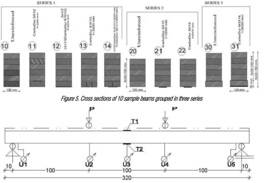
To obtain as reliable data as possible while testing, it is necessary to take as many samples as possible in order to get the results which could be analysed using statistical methods (Figure 4). For the research purposes, 10 beams were made and divided in three groups of which one beam was unstrengthened, and the rest were strengthened with various amounts of reinforcement in different spots. Positions of the reinforcement were carefully chosen to closely
represent practical cases preformed in rehabilitation of structures. In Figure 5 dimensions of cross sections for every group of samples are given, and in addition, the position, type and length of reinforcement.
The choice of the beams length and cross sections was made according to the manufacturers recommendations related to the testing of timber beams, where there is no need for taking the stress corrections. Series 1 consist of 4 samples, series 2 is lower for the height of one lamella and consists of three samples, while the samples from the series 3 are almost the same height as the samples from the series one, and consists of three samples. Every sample has one unstrengthened sample.
Deflection measuring instruments were placed in the middle of the span (largest deformation), at supports and at the points where the pressure was applied (Figure 6). The measurements at supports were important, since the deflections occurred due to crushing of timber, which affected the deflection in the middle of the span. Additional tensometers were used during the experiment for control measurements. Strain gauges were used for measuring dilatations by electric reading in the middle of the span on the top and bottom lamellas.
The aim of the experiment was not to cause the fracture in the beams, but to monitor the behaviour of the specimens in elastic and plastic deformation range. After the measurement, the zero reading was performed as well as the control of residual deformation.
Research results analysis
Samples were exposed to bending in a way that the load was applied in several steps. For the future analysis only one representative measuring is given. In order to show results, deflections in the middle of the specimen from the series 1 are given in Figure 7. It can be seen from the graph that behaviour of every sample was liner up to the point when load bearing capacity reached 2x24(48)kN. After reaching this point deformations grew faster. The same behaviour can be noticed for series 3, while the series 2 (cross section with less height) reaches the critical load at 2x22.5(45)kN.
Using these observations two characteristic zones in which the sample can be found can be distinguished:
Zone I, linear elastic behaviour between deflection and load, so only the behaviour of the specimen for the load level of 2x10(20) kN and 2x20(40) kN will be taken for further analysis
Zone II, non-linear behaviour between deflection and load – the zone of unpredictable specimen behaviour for the higher load level: − Series 1, the deformation of the sample was
manifested in the form of irregular crushing of timber fibres on the surface (more than 3mm), where the load was applied at supports as well, which caused section warping and rotation of the entire sample, − Series 2, deformation of the unstrengthened
specimen no. 20 led to vertical fracture in the middle of the range, while in case of strengthened specimen no 22, the fracture appeared in the timber under the strengthened lamella, Figures 8 and 9, and − Series 3, the deformation appeared in the
strengthened sample no 31, as a fracture, but in the spot where the strengthening was ending.
Figure 5. Cross sections of 10 sample beams grouped in three series
Figure 6. Testing subject with positions of measuring instruments (measures are given in cm)
Numerical model
3D numerical beam model was developed in the AxisVM ® software package based on the finite element method. It supports important features for modelling transient and boundary conditions using the links for two types of elements (lamella-lamella and (lamella-lamella-carbon, ’link’ finite element), and for beams using a shell (’Shell’ finite element). The bond between the wooden lamellas was accomplished with the glue for wood, while the connection of lamellas and FRP strips was formed with two-component epoxy adhesive. Used ’Shell’ finite elements have three translational degrees of freedom and three rotational degrees of freedom in the finite element node. The final element in the node comprises stress state caused by axial force, bending and shear. To define the parameters determining final elements, the input data of mechanical properties of the material were used (class of laminated wood, the data from the FRP strips and epoxy adhesives testing), cross section geometry and beam-model span obtained by previous research (Section on previous examination). To be precise, these technical characteristics are as follows: − for timber: Ex=11,000kN/cm2 or
Ex=16,748, Ey=37kN/cm2, (Ex-modulus of
elasticity for timber parallel to wood fibres, Ey- modulus of elasticity for timber perpendicular to wood fibres),
ν=0.21(Poisson ratio), αt=8x10-61/˚C
(thermal expansion ratio), ρ=420kg/m3
(timber mass) and d=32mm (timber lamella thickness),
− for FRP strip, type S: Ex=16,500kN/cm2,
Ey=16,500kN/cm2, ν=0, α
t=4x10-71/˚C,
ρ=1,800kg/m3 and d
s=1.2mm and
− for FRP strip, type M: Ex=21,000kN/cm2,
Ey=21,000kN/cm2, ν=0, α
t=4x10-71/˚C,
ρ=1,800kg/m3 and d
M=1.4mm.
In order to achieve greater accuracy sections were divided into final elements, 10cm in length, which define positions of the load and strengthening FRP strips length. The bond between lamella and FRP strips was made
through translational and rotational stiffness, which was 107kN/m and 107kNm/rad, for the supports stiffness of 105kN/m/m.
As a result of the 3D model calculations, a wired model with iso-surfaces in various modes was obtained. State of deflection of the specimen no. 10 is presented in the Figure 10. Similar iso-surfaces were obtained for tensile and compression stress states for this and other specimens.
Analysis of measured and calculated results
Data for deflexion and normal stresses in the top and bottom lamellas of the beams, in timber as well as in reinforcement, are taken for comparison of numerical and measured values. The differences in results are obtained from experimental testing and numerical model. In all cases the measured deflections are lower than the computational, as well as stresses. Deflections analysis points out small differences between measured and calculated deflections, which would almost overlap perfectly if presented by curves.
Numerical analysis of the model was performed with the two modulus of elasticity, E = 11,000N/mm2 modulus of elasticity
(provided by the EN 1194 for glulam GL24h), and E=16,748N/mm2 modulus of elasticity, obtained
by examining the structure in this study.
If measured values are compared to numerical ones, for the first value of modulus of elasticity, it can be noticed that computational deflections are 26-58% higher than measured. The similar situation is with computational tension in timber which is 20-37% higher than measured. Computational tension in carbon is 0-46% higher, while this ratio for the pressure in timber varies between 26-63%. Comparing measured with computational values, for real modulus of elasticity, these variations are getting lower. Computational deflections values are higher by 3-12%, tension stresses in timber are higher by 0-46%, while pressure stress is larger by 0-13%. The conclusion can be derived from the analysis that the numerical model is reliable and safe, so it can be used for static analysis for beams retrofit.
Figure 8. Cracking and crushing of timber fibres in the sample no. 22
Figure 10. 3D deflection surface for the model no. 10
CONCLUSION
Numerous advantages of using carbon FRP strips for strengthening glulam beams were listed in the paper. Certain conclusions necessary for implementation of this system in retrofit of new and existing structures were derived from research on specimens and computational models. Contribution to strengthening of timber glulam beams by using FRP strips enhancing tensile strength up to 40-60% (Johnsson, 2006) was stated in cited papers. In this research, following conclusions were obtained from laboratory testings: − Comparing the non-reinforced specimens
with the reinforced ones, deflections are reduced by about 20%, stresses by 25% and flexural stiffness is increased by 24%. − Horizontal reinforcement is better than
vertical, since it gives smaller deflections and stresses and enables great rigidity. − The best position for the reinforcement is
below lowest lamella.
− Full contribution of the reinforcement is obtained when FRP strip is extended over the supports, along the entire span of the beam, because it receives bending and shear forces, and at the same time prevents torsion.
− Deflections and stresses decrease when reinforcement surface increases.
− Measured values for deflections and stresses are lower than results obtained from numerical models.
− Strengthening with FRP strips with higher modulus of elasticity enables greater capacity.
− Increasing loads leads to reaching critical value of stresses in the cross section of the beam, and finally to fracture of the element, defined as failure. Failure of each element occurred in tensioned zone of the timber. Based on these observations it can be said that FRP strip reinforcement applied on timber beams improves load bearing capacity, and is dependent on parameters that were modified in this study: position, length and surface of reinforcement.
In order to obtain high-quality reinforcement of glued laminated beams it is necessary to proceed with further research in this area. It might be interesting to direct further research onto behaviour of timber glulam beams exposed to permanent load (load being applied for longer than three years), since it is known that timber's load bearing capacity reduces by up to 40%, and FRP strips have minimal extension. Frame and arch structures are
interesting for testing as well. Further studies in this field should be focused on the zone of unpredictable behaviour of the beam with rotation and warping of the cross section appearing. This phenomenon could be prevented by placing pads of various sizes on load application spots and inserting side supports – stiffeners in various places.
References
Bajić, T., Pantović, K. (2012) Mogućnosti primene modularnih sistema u projektovanju održivog i klimatski svesnog socijalnog stanovanja, Arhitektura i urbanizam 33, pp. 42-59.
Bohannan, B. (1962) Prestressed wood members, Forest Products Journal, Vol. 12(12), pp. 596-602.
Jobin, J., Garzon-Barrragán, O. L. (2007)
Flehural Strengthening of Glued Laminated Timber Beams with Steel and Carbon Fiber
Reinforced Polymers, Master's Thesis,
Chalmers University of Technology, Göteborg, Sweden.
Johnsson, H., Blanksvärd,T., Carolin, A. (2006) Glulam members strengthened by carbon fibre reinforcement, Material and Structures, No. 40, pp. 47-56.
Kitek Kuzman, M., Oblak, L., Vrantuša, S. (2010) Glued Laminated Timber in Architecture, Drvna
industrija, No. 61, pp. 197-204.
Kosorić, V. (2012) Živeti bliže okruženju-koncept
kuće, Arhitektura i urbanizam, 32, pp. 16-26.
Mark, R. (1961) Wood-aluminum beams within and beyond the elastic range, Forest Products
Journal,Vol. 11(10), pp. 477-484.
Nenadović, A. (2010) Development,
characteristics and comparative structural analysis of tensegrity type cable domes,
SPATIUM International Review, No. 22,
pp. 57-66.
Ogawa, H. (2000) Architectural application of carbon fibers Development of new carbon fiber reiforced glulam, Carbon, No. 38, pp. 211-226. Okrajnov-Bajić, R. (2009) Self-compacting
concrete and its application in contemporary architectural practise, SPATIUM International
Review, No. 20, pp. 28-34.
Solarov, R., Kovačević, D., Radonjanin, V., Glišić, M. (2011) Armiranje drvenih lameliranih nosača sa karbonskim trakama, XXV Kongres i simpozijum o istraživanjima i primeni
savremenih dostignuća u građevinarstvu u
oblasti materijala i konstrukcija, DIMK, Tara,
pp. 259-271.
Theakston, F. H. (1965) A feasibility study for strengthening timber beams with fiberglass, Canadian Agricultural Engineering
7(1), pp. 17-19.
Vavan-Vučeljić, S. (2010) Analiza mogućnosti povećanja energetske efikasnosti zgrada primenom fazno-promenjivih materijala,
Arhitektura i urbanizam 27, pp. 78-87.
2