Innovative retrofitting materials
for brick masonry infill walls.
DECLARATION
Name: Juan Mora Gómez Email: [email protected]
Title of the MSc Dissertation:
Innovative retrofitting materials for brick masonry infill walls.
Supervisor(s): Graça Vasconcelos / Raul Fangueiro Year: July 2012
I hereby declare that all information in this document has been obtained and presented in accordance with academic rules and ethical conduct. I also declare that, as required by these rules and conduct, I have fully cited and referenced all material and results that are not original to this work.
I hereby declare that the MSc Consortium responsible for the Advanced Masters in Structural Analysis of Monuments and Historical Constructions is allowed to store and make available electronically the present MSc Dissertation.
University: University of Minho Date: 17 July 2012 Signature:
Innovative retrofitting materials
for brick masonry infill walls.
ACKNOWLEDGEMENTS.
First mention of gratitude is to Professor Graça Vasconcelos for her fundamental guidance as supervisor of this thesis, providing her assistance, advice and encouragement. In addition, special thanks to Professor Raul Fangueiro for his valuable advice as co-supervisor.
Another very special mention is to the Erasmus Mundus scholarships program, for the financial support that allowed me to join the SAHC master program.
The experimental campaign was conducted at both Civil Engineering Laboratory and Textile Engineering Laboratory, in Azurem Campus of University of Minho. The assistance of the entire staff of both laboratories and the fellow researchers, as well as the cooperative and friendly ambience is greatly appreciated. The production of the textile materials was done in cooperation with Fernando Cunha, to whom I am very grateful for his patient introduction to the field of textile engineering. A special mention is also deserved by Elisa Poletti and Mr. Matos for their time and help in the introduction to laboratory techniques and in the developing of a very demanding work.
Last but most important, thanks to all my SAHC fellows for making this experience so interesting and for the dose of humour needed for learning.
ABSTRACT.
Last seismic events in Southern Europe have highlighted the vulnerability in the most usual constructive typology in contemporary architecture: framed structures with masonry infills. Contemporary structures have a good capacity to withstand these actions, given that they were considered for their design according to modern codes. Nonetheless, nonstructural elements as masonry infills show a high degree of damage even for medium magnitude earthquakes, causing casualties and high economic losses. For decades, these elements have been considered as nonstructural and therefore they were not requested to have resisting conditions.
Given this, there is a large segment within the building stock in seismic prone areas that needs to undergo preventive action, specially for out-of-plane loads. This can range from a mere union of the infills to the frame structures to a reinforce of the elements, which can also be applied to the case of already damaged elements. The potential benefits go beyond the mere stability of nonstructural elements, as this would improve the behaviour of the whole structure to face seismic events.
Some new fibre-based materials for structural reinforcement based in braiding techniques have been developed in the last years in the Universidade do Minho, as an alternative to conventional FRP rods. These materials have several advantages, out of which it can be remarked the possibility of designing the composition according to mechanical requirements and the implication of low-tech and low-cost procedures for its production.
The main purpose on this thesis will be the assessment of the application of this material as reinforcement for clay brick masonry, using the technique of Textile Reinforced Mortars, considering out-of-plane actions. This has been done through a basic experimental campaign in which it has been evaluated the improvement in the behaviour of masonry samples subjected to flexural loads. The material was applied with variations in reinforcement ratio in order to have some parametrical confrontation. Other samples included commercial solutions, so as to have a reference on already existing materials, and the control samples were unreinforced.
The obtained results for the innovative materials were highly satisfying in terms of ductility enhancement, obtaining big deformations with a considerable flexural capacity, and a considerable increase in strength. Furthermore, the use of different materials within a composite results in the combination of its properties.
The future development and enhancement of this material presents a high potential as an economic and easy to apply method for brick masonry reinforcement, with the possibility of tailor-made properties..
RESUMO.
Os recentes eventos sísmicos ocorridos no sul da Europa destacaram as vulnerabilidades de um dos sistemas construtivos mais utilizados na arquitectura contemporânea: estruturas em pórtico preenchidas com paineis de alvenaria. Enquanto as estruturas modernas, dimensionadas de acordo com os códigos em vigor, resistem bem a esse tipo de acções, o mesmo já não se passa com os elementos não-estruturais. De facto, é comum os paineis de alvenaria sofrerem elevados danos, mesmo para sismos de intensidade media, causando vitimas fatais e elevadas perdas económicas. Durante décadas estes elementos foram considerados como sendo não-estruturais e consequentemente nunca lhes foi exigido quaisquer propriedades the resistência.
Sendo assim, é natural que nas zonas sismicas exista uma larga porção de patrimonio edificado com necessidade de sofrer medidas preventivas, especialmente para acções fora do plano.Estas medidas podem significar desde a simples união dos paneis à estrutura até um reforço dos elementos individuais da alvenaria, o qual pode ser aplicado mesmo que já existam danos. Os potenciais benefícios destas técnicas vão para além da mera estabilidade destes elementos uma vez que o seu reforço poderá implicar uma mehoria das caracteristicas sismicas da estrutura como um todo.
Durante os últimos anos a Universidade do Minho tem vindo a desenvolver novos materiais à base de fibras como alternativa aos sistemas convencionais de polimetros reforçados com fibras (FRP).. Estes materiais possuem várias vantagens entre as quais se destaca a possibilidade de poderem ser dimensionados com base em requisitos mecânicos de uma forma barata e tecnologicamente acessível.
O principal objectivo desta tese é a avaliação da aplicação deste material como reforço de alvenaria de tijolo cerâmico, utilizando a técnica de argamassas reforçadas com texteis e considerando acções fora do plano. Este estudo foi realizado através de uma série de ensaios experimentais simples, na qual foi avaliada a melhoria do comportamento de várias amostras sujeitas a cargas de flexão. Vários espécimens foram preparados com diferentes densidades de reforço, de modo a possibilitar a comparação de vários parâmetros. Outras amostras incluíram soluções comerciais, de forma a ter uma referência de materiais já existentes, e amostras de controlo não-reforçadas.
Os resultados obtidos para os materiais inovadores foram altamente satisfatórios em termos de aumento de ductilidade, tendo-se verificado deformações elevadas enquanto mantendo uma
RESUMEN.
Los últimos eventos sísmicos en el Sur de Europa han puesto de relieve la vulnerabilidad de una de las tipologías constructivas más usuales de la arquitectura contemporánea: las estructuras porticadas –metálicas o de hormigón- con cerramientos de ladrillo. Si bien las estructuras soportan bien las acciones, los elementos no estructurales como fachadas o petos sufren graves daños, provocando altas pérdidas económicas y víctimas mortales incluso para acciones sísmicas de mediana magnitud. Durante décadas, estos elementos constructivos se han considerado no estructurales, y por tanto no se les han exigido condiciones de resistencia.
Nos encontramos por tanto con un amplio sector del parque inmobiliario en zonas de riesgo sísmico necesitado de acciones de prevención. Dichas acciones incluyen una mejor unión de los cerramientos a la estructura general, así como posibles refuerzos de los elementos en sí. El beneficio, más allá de la estabilidad de los elementos en sí, incluye un mejor comportamiento de la estructura general ante acciones sísmicas
En la Universidade do Minho se han venido desarrollando nuevos materiales de refuerzo estructural, basados en la técnica del entrenzado de fibras, como alternativas a las barras de FRP convencionales. Estos materiales están compuestos por un núcleo de material resistente rodeado de una funda entrenzada de material económico, que mejora la adherencia del material al mortero a la vez que protege al núcleo del ataque alcalino. Entre sus ventajas, la posibilidad de diseñar composiciones del material dependiendo de los requerimientos mecánicos y el uso de una tecnología sencilla y de bajo coste. La producción y caracterización de estos materiales será tratada a fondo en este trabajo.
La validación de estos nuevos materiales en su aplicación al refuerzo de muros de fábrica de ladrillo se ha hecho mediante una campaña experimental básica, comprobando la mejora que supone su uso en la resistencia a flexión unidireccional de unas muestras de obra de fábrica, realizados con los materiales más usuales para esta solución constructiva. Se ha intentado confrontar el resultado de estos materiales, con parámetros variables, con el de materiales disponibles comercialmente, así como con muestras de control sin refuerzo.
Los resultados obtenidos para los materiales desarrollados son muy satisfactorios en cuanto a la mejora de la ductilidad, obteniendo grandes deformaciones manteniendo la capacidad de carga, incluso para ratios de refuerzo relativamente bajos. Para los ejemplares con más refuerzo, se observa además una redistribución de tensiones dentro de la fábrica, dando lugar a un fallo a flexión muy dúctil y a un comportamiento con incremento de resistencia en el estado fisurado.
El desarrollo de este material presenta una gran potencialidad como método económico y de fácil aplicación para el refuerzo de muros de fábrica
CONTENTS.
Chapter 1. Introduction. ... 1
1.1. Objectives of the thesis ... 2
1.2. Organization of the thesis ... 3
Chapter 2. Masonry infills under seismic actions: General overview. ... 5
2.1. Characterization of masonry infills. ... 6
2.1.1. Historical introduction. ... 6
2.1.2. Classification: material, typology. ... 7
2.1.3. Mechanical characterization of existing masonry. ... 10
2.2. Behaviour of masonry infills under seismic action. ... 11
2.2.1. Influence of infill walls in the general structural behaviour under seismic actions. ... 11
2.2.2. Importance of the constructive detail and execution of the infills. ... 13
2.4. Estimation of the requirements according to EC8. ... 15
Chapter 3. Effect of seismic actions on infill walls and retrofitting techniques: state of the art ... 17
3.1. Effect of seismic actions on masonry walls: In plane action. ... 18
3.3. Effect of seismic actions on masonry walls: Out of plane action. ... 24
3.4. Examples in last European earthquakes. Lorca, L’Aquila. ... 26
3.5. Modeling of infill walls. ... 29
3.5.1. Numerical approaches... 29
3.5.2. FEM. ... 31
3.6. Analysis of the retrofitting schemes used for masonry infill walls. ... 33
3.6.1. Steel fiber composite concrete shot. ... 33
3.7.2. TRM vs. FRP – Researches by Papanicolau and Triantafillou ... 38
3.7.3. Expected modes of failure in walls reinforced with TRM. ... 39
3.7.4. Commercial solutions: overview. ... 40
Chapter 4. Development of textile braided materials. ... 41
4.1. Innovative materials: braided fibre-reinforced rods. ... 42
4.2. Material composition. ... 43
4.3. Manufacture of the retrofitting materials. Methodology. ... 44
4.4. Geometrical characterization of the braided materials. ... 46
4.5. Manufacture of textile braided meshes. ... 48
4.6. Mechanical characterization of braided bars. Uniaxial tensile tests. ... 49
4.6.1. Test set-up and procedures. ... 49
4.6.2. Results of the tests. ... 52
4.6.3. Analysis and discussion of the results. ... 54
4.7. Commercial solutions. ... 58
4.8. Designation of the reinforcements to be tested. Comparison of mechanical properties. ... 59
Chapter 5. Experimental campaign on reinforced masonry. ... 61
5.1. Definition of the samples. ... 62
5.1.1. Definition of the geometry of the masonry samples. ... 62
5.1.2. Definition of the materials for the wall samples. ... 64
5.1.3. Construction of masonry panels and retrofitting. ... 64
5.1.4. Definition of the retrofitting schemes. ... 66
5.2. Mortar control and testing. ... 68
5.3. Brick control and testing. ... 69
5.4. Design of the test setup. ... 70
5.5. Theoretical characterization of the flexural strength of masonry walls ... 72
5.5.1. Compressive strength of masonry. ... 72
5.5.2. Theoretical estimation of the flexural strength. ... 72
5.6. Assumptions for analysis of experimental results. ... 76
5.6.1. Measurement of displacements. ... 77
5.6.2. Calculation of flexural stress within the elastic range. ... 78
5.6.3. Estimation of elastic modulus. ... 78
5.7. Typologic analysis for each type of reinforcement. ... 78
5.7.1. Unreinforced masonry. Reference samples. ... 79
5.7.2. Masonry specimens retrofitted with 2G #6. ... 80
5.7.3. Masonry specimens retrofitted with 4G #6. ... 82
5.7.4. Masonry specimens retrofitted with 2G #3. ... 84
5.7.5. Masonry specimens retrofitted with Mapei Mapegrid. ... 86
5.7.6. Masonry specimens retrofitted with the mesh from S&P. ... 88
5.8. Comparative analysis. ... 90
5.8.1. Influence of spacing and glass fibre content. ... 91
5.8.2. Comparation with commercial solutions. ... 93
5.8.3. Comparison of cracking patterns and failure modes. ... 95
5.9. Analytical vs. experimental results. ... 98
5.10. Comparison with other researches and solutions. ... 99
Chapter 6. Conclusions and future work. ... 103
6.1. Conclusions. ... 103
6.1.1. Braided materials ... 103
6.1.2. Performance of the materials as reinforcement for clay brick masonry walls. ... 103
6.1.3. Comparison of analytical estimation and observed results. ... 105
LIST OF FIGURES.
Figure 1. Evolution of masonry infill walls in Southern Europe. [8] ... 7
Figure 2. Most usual block typologies, according to the percentage of voids and the necessity of rendering. [10] ... 9
Figure 3. Design and construction parametres affecting the infill performance . [1] ... 14
Figure 4. Seismic hazard in Europe, measured as expected peak ground acceleration with 10% of probability of excedence in 50 years (source: European Seismological Commission, 2003) Many of the seismic regions, such as the Mediterranean area, share common constructive practice... 15
Figure 5. Modeling of seismic behaviour before and after detachment of masonry infill [7] ... 18
Figure 6. Modes of failure of infilled frames [24]. ... 19
Figure 7. Typical crack pattern and dislocation for out of plane actions [25] ... 24
Figure 8. Typical diagonal in-plane cracking of infills [28] L’Aquila. ... 26
Figure 9. Out-of plane failure, overturning of the external leave or the whole infill [28]. L’Aquila. ... 26
Figure 10. Failing of the exterior leaf due to improper connection [1] L’Aquila. ... 26
Figure 11. Out of plane damage in several degrees: from diagonal-central cracking to complete overturning and expulsion of infills [28] L’Aquila. ... 27
Figure 12. mix of in-plane and out-of-plane actions in a free corner [29] Lorca. ... 27
Figure 13. (a) Out of plane collapse of infill walls;( b) Wall panel rotation; (c) Horizontal hinge formation; (d) Total collapse of the single leaf wall [1] L’ Aquila. ... 27
Figure 14. (a) Short column and corner crushing of the infill; (b) In–plane cracking and crushing of masonry wall (c) Horizontal bed joint sliding [1] L’Aquila. ... 28
Figure 15. L’Aquila. [30] ... 28
Figure 16. L’Aquila. [30] ... 28
Figure 17. Strut analogy [33] ... 30
Figure 18. Limit equilibrium analysis in out-of plane failure of masonry infills [32] ... 31
Figure 19. Failure by deep cracking and crushing of brick. [50] ... 39
Figure 20. Debonding and disintegration of the mortar matrix. [50] ... 39
Figure 21. Slipping of the fibres within the mortar matrix [49]. ... 40
Figure 22. Tensile failure of fibres [50]. ... 40
Figure 23. Materials used in the manufacture of the braided retrofitting materials: ... 43
Figure 24. Braiding machine. ... 45
Figure 25. Detail of the braiding process. ... 45
Figure 26. Tensioning of the produced material. ... 45
Figure 27. Manual application of polyester resin. ... 45
Figure 28. Equipment for the determination of geometrical properties. ... 46
Figure 29. Measurement of the diametre with Vernier caliper.. ... 46
Figure 31. 4G rods. Magnification. ... 47
Figure 32. 2G rods. Braiding angle: 24.1º ... 47
Figure 33. 4G rods. Braiding angle: 25.7º ... 47
Figure 34. 2G rods. Rib angle. ... 47
Figure 35. 4G rods. Rib angle. ... 47
Figure 36. Manual assembly of the mesh... 48
Figure 37. Equipment used for the tensile tests. ... 49
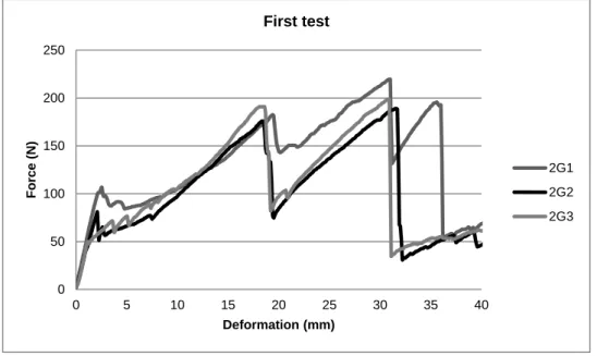
Figure 38. Force – elongation graph for 2G rods in the first tests. ... 50
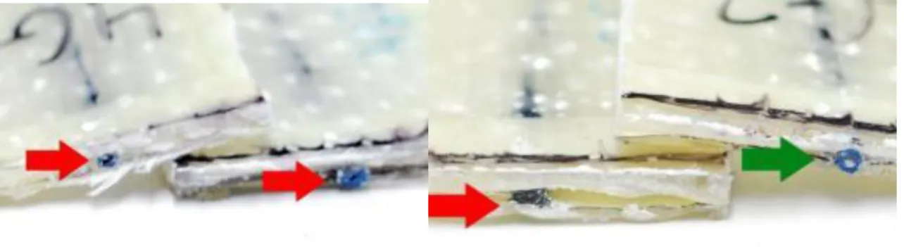
Figure 39. Red: points where sliding is noticed. Green: sample where the core did not slide. ... 51
Figure 40. Example of broken sample. The sliding of the fibres is not noticeable at first glance. ... 51
Figure 41. Other type of failing: the whole rod slides into the composite plates. ... 51
Figure 42. Up: first test samples. Down: second test samples, exposing glass fibres. ... 51
Figure 43. Tensile behaviour of external braids without reinforcement (2350 tex of polyester). ... 52
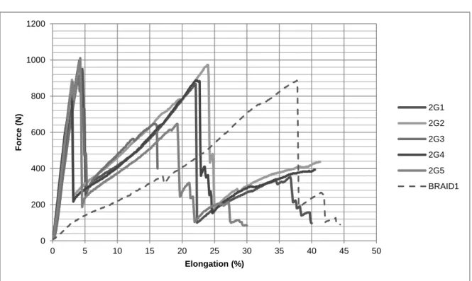
Figure 44. Force – elongation diagrams obtained for 2G rods (816 tex of glass fibre), and comparison with behaviour of external braid. ... 53
Figure 45. Force – elongation diagrams obtained for 4G rods (1632 tex of glass fibre), and comparison with behaviour of external braid. ... 53
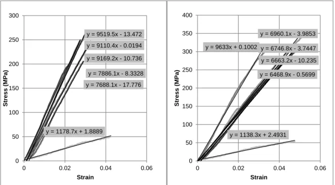
Figure 46. Calculation of elasticity of the materials. Left, 2G rods. Right, 4G rods. ... 54
Figure 47. Analysis of results for representative examples of each element. ... 55
Figure 48. Internal bonding in the reinforcement rods after glass fibre failure. ... 57
Figure 49. SP ARMO L500 and its components. ... 58
Figure 50. Mapegrid G220 and its components. ... 59
Figure 51. Left: test samples for previous experimental campaign. Right: design of samples for experimental campaign in this thesis. ... 63
Figure 52. Dimensional parameters of samples according to UNE-EN-1052. ... 63
Figure 53. Construction of the walls. Leveling and control of bed joint thickness. ... 65
Figure 54. Application of reinforcement meshes in the render. ... 65
Figure 55. Retrofitting schemes of textile composite meshes composed from the association of composite textile rods ... 67
Figure 56. Mortar flexural strength test. ... 68
Figure 64. Representative parametres in the load-deflection diagram. ... 77
Figure 65. Relation of measured displacements in a given sample. ... 77
Figure 66. Behaviour of unreinforced samples in elastic range. Estimation of stiffness. ... 79
Figure 67. Crack pattern for unreinforced samples ... 79
Figure 68. Load-displ. diagrams,2G#6: General behaviour. Elastic range. Estimation of stiffness. ... 81
Figure 69. Specimen retrofitted with 2G#6: Crack pattern. ... 81
Figure 70. Load-displ. diagrams, 4G#6: General behaviour. Elastic range. Estimation of stiffness. ... 83
Figure 71. Specimen retrofitted with mesh 4G#6: Crack pattern. ... 83
Figure 72. Load-displ. diagrams, 2G#3: General behaviour. Elastic range. Estimation of stiffness. .... 85
Figure 73. Specimen retrofitted with mesh 2G#3: Crack pattern. ... 85
Figure 74. Load-displ. diagrams, Mapei: General behaviour. Elastic range. Estimation of stiffness. ... 87
Figure 75. Specimen retrofitted with mesh from Mapei: Crack pattern. ... 87
Figure 76. Load-displ. S&P: General behaviour. Elastic range. Estimation of stiffness. ... 89
Figure 77. Specimen retrofitted with mesh from S&P: Crack pattern. ... 89
Figure 78. Scheme of the behaviour of composite-reinforced masonry. ... 91
Figure 79. Comparative of general behaviour of significant samples with innovative material. ... 92
Figure 80. Behaviour of the reinforcements. ... 92
Figure 81. Comparative of general behaviour of significant samples of each type. ... 94
Figure 82. Comparative of cracking behaviour of significant samples of each type. ... 94
Figure 83. Comparison of typical failure modes of different reinforcements. ... 97
Figure 84. Envelopes for hysteretic curves for masonry reinforced with carbon textile fibres [49] [48]. ... 100
Figure 85. Comparison of the flexural behaviour of specimens reinforced with TRM - basalt and glass with different mortars. [50] ... 100
LIST OF TABLES.
Table 1. Typical degree of damage for bed joint sliding [11] ... 20
Table 2. Typical degree of damage for corner crushing [11] ... 21
Table 3. Typical degree of damage for diagonal tension cracking [11] ... 22
Table 4. Typical degree of damage for corner crushing and diagonal cracking [11] ... 23
Table 5. Typical degree of damage caused by out-of-plane actions [11] ... 25
Table 6. Geometrical characterization of produced materials. ... 47
Table 7. Results derived from tensile tests of reinforcing rods. ... 56
Table 8. Summary of mechanical values for all used materials. ... 60
Table 9. Definition of retrofitting schemes. ... 66
Table 10. Brick compressive strength. ... 69
Table 11. Theoretical compressive mechanical of masonry material. ... 72
Table 12. Theoretical ultimate loads for each reinforcement type. ... 75
Table 13. Theoretical ultimate loads for each reinforcement type. ... 76
Table 14. Obtained values for unreinforced masonry. ... 79
Table 15. Obtained values for 2G#6 reinforcement. ... 80
Table 16. Obtained values for 4G#6 reinforcement. ... 82
Table 17. Obtained values for 2G#3 reinforcement. ... 84
Table 18. Obtained values for Mapei reinforcement. ... 86
Table 19. Obtained values for S&P reinforcement. ... 88
Table 20. Comparative analysis of resisting and deformation flexural parametres. ... 90
Table 21. Significant images for failure modes by typology. ... 95
Table 22. Final expected load in kN. Estimations according to analytical models and obtained results. ... 98
Table 23. Technical data for the yarns of glass fibre. ... 115
Table 24. Technical data for Mapegrid G220. ... 115
LIST OF ABREVIATIONS.
RC – reinforced concrete URM – unreinforced masonry CM – confined masonry RM – reinforced masonry FRP – fiber reinforced polymers
GFRP – glass fiber reinforced polymers CFRP – carbon fiber reinforced polymers TRM – textile reinforced mortar
CHAPTER 1.
INTRODUCTION.
The development of reinforced concrete along last century was supported by exhaustive research, mathematical and physical theorization and modelling, and consequent progressive improvements that made it the most affordable and reliable material for structural design. This way, now days this is the prevalent typology within the contemporary built stock in Europe. Experience and research helped to develop standards and building codes increasingly strict and safe, with a better understanding of actions such as earthquake, and solutions to face them.
Nonetheless, this increasing structural requirements were mainly applied only to the purely concrete or metallic structural skeleton, neglecting the non-structural elements such as the brick masonry infills that for decades have constituted the most common solution for enclosing and façading. These elements have undergone development, but regarding mainly their enclosing and isolating functions, and forgetting their resisting role, since this requirement is only evidenced in limited, and normally accidental occasions.
Last seismic events in Southern Europe have shown that the contemporary building stock can withstand earthquakes reasonably well under the point of view of collapse, when compared to the ancient and traditional masonry structures, which show a higher vulnerability. Nonetheless, the damages in non-structural elements have been a major cause of both casualties and economic loss [1] [2]. Failure and overturning of façades and parapets induced by out-of-plane load, and major damage of the infills for in-plane loads are common in reinforced concrete buildings even if the main structure remains undamaged. This shows that a big part of the building stock is highly exposed to high cost damages and to life security even for medium-size seismic events.
Preventive actions should consider the enhancement of the behaviour of this non-structural elements, both by considering an adequate connection between the supporting structure and the infills (a solution more frequent now days, but quite rare in buildings from past decades), and by retrofitting them by means of affordable and feasible techniques.
Given this, the objectives of any constructive solution that might be developed to enhance the behaviour of these non-structural elements to earthquakes and other accidental loads such as blast-
- Raising the cracking load for the element, reducing the damage and thus the economical losses.
Several materials and techniques have been developed and tested as retrofitting possibilities for these elements, from the early application of ferrocement to the more recent retrofitting technique based on Fibre Reinforced Polymers (FRP). Their application can range from the preventive aspect for hazardous elements previous to their damage, to the strengthening in lightly damaged elements, preventing further damage in future seismic events.
In a first approach, FRPs seem to have the best mechanical performance for this kind of application. They provide both high strength and a fairly ductile behaviour. On the other hand, their application has many disadvantages due to the use of resins for the matrix. One of the developed alternatives has been textile reinforced mortars (TRMs), that use the same reinforcing fibres, mainly glass and carbon, but within a textile structure and embedded in a mortar matrix. This solution is more recent and few studies are available on its performance when applied in the retrofitting of masonry infill walls. With this respect, among the problems to be solved is the possibility for the composite material to debond, which implies an ineffective use of the material, and the potential reactivity of the mortar to some of its components that can lower its durability.
1.1.
Objectives of the thesis
Following the need of studying retrofitting strategies to improve the seismic behaviour of masonry infill walls, textile reinforced mortar technique was adopted to be analysed in the scope of this thesis. The textile materials used here continue a research line of development of braided materials carried out in University do Minho [3]. The textile materials are proposed as an alternative to conventional FRP rods, produced using simpler and lower cost technology (braiding). In short, these materials consist of a core of high resistance material such as carbon or glass fibres, coated on a braided tubular structure of cheaper material, namely polyester. This external braid should carry out two important functions: improving the bonding to the mortar in which the rods will be embedded, through the creation of a ribbed structure in the braided shell, and the protection of the inner core to the potential reactivity of the alkali components of mortar. Previous research studied the application of these materials as an alternative to steel reinforcement of concrete [4] [5] [6].
Thus, the main objective of this thesis is to assess the behaviour of these innovative materials in the retrofitting of typical brick masonry infill panels. Though the experimental campaign only focuses on contemporary materials, the applications are wider, and could be extrapolated easily to historical masonry.
In detail, the objectives are: (1) study of innovative materials for retrofitting masonry infill walls based on textile reinforced mortar (textile braided materials embedded in mortar); (2) characterize the
performance of the innovative retrofitting techniques in the improvement of the out-of-plane behaviour of masonry brick walls; (3) comparison of the innovative solution with other existing techniques. In relation to the previous work [3], which compared distinct internal core material for the braided bars (carbon fibre core, glass fibre core and polyester), some improvements and modifications have been made, such as the development of the ribbed structure to improve the bonding, and the application of a resin in the braided bars to make it more effective in the resistance of the composite material. Besides, in this thesis only one type of reinforcing material (glass fibre) was considered in all the samples, to have the possibility of assessing the effect of varying parameters affecting the density of reinforcing material, such as the amount of reinforcement and the spacing of the rods. There will be also a comparison with two commercial solutions of meshes to be embedded in mortar.
Both the production of the strengthening materials and the obtaining of data for analysis imply large amount of laboratory work due to (1) the semi-manual process of production of the braided materials and to the need of a thorough characterization of all the implied components and (2) the experimental campaign for the evaluation of the performance of the developed materials as a retrofitting technique for the enhancement of the out-of-plane behaviour of masonry infill walls and their comparison. Here, there will be a special care on the analysis of improvement on strength and deformation capacity of the retrofitting materials, as well as possible comparison with the commercial solutions, both quantitatively and qualitatively, as well as with other research on TRM available in literature.
The designed experimental campaign is quite basic, studying only the improvement of behaviour to simple flexure as comparable parameter, given that this is only a first approach to the use of the material in masonry reinforcement. Further empirical studies, with improvements drawn from this thesis, should go further for a more realistic behaviour of reinforced masonry under seismic loads.
1.2.
Organization of the thesis
The thesis is divided into five chapters besides the introduction (Chapter 1).
In the second Chapter, it is provided a wide review on general topics related to both masonry and seismic actions. This is mainly centred on the current building codes and standards, and their consequences on building techniques.
Chapter five explains the application of this reinforcing materials to masonry samples, and goes through the whole experimental campaign. This includes the design of the samples and the experimental setup, the mechanical characterization of the masonry components, an analytical estimation of the expected behaviour based on material models, and the analysis of the results obtained from the experimental campaign. This analysis will be done both for each typology of reinforcement considered and comparing the different solutions among them.
In Chapter six the conclusions and recommendations for future development are provided.
There is also an appendix of annexes, including all sort of data that can be helpful for further understanding of the reader of certain points of the work done.
CHAPTER 2.
MASONRY INFILLS UNDER SEISMIC ACTIONS:
GENERAL OVERVIEW.
Through this section, the main background of the particular research done in this thesis will be reviewed in order to give an initial thread to the further development of specific parts of the whole frame here described. This first part will consist in an introduction to the two main topics to be treated in the research project: masonry infills and seismic behaviour.
First, there will be a description of the typology of masonry infills in reinforced concrete structures, and their importance within the contemporary building industry. The overview includes aspects about their possible classification with structural implications and some problematics, according to the European reference codes.
Then, a short introduction into a complex topic, the seismic behaviour of reinforced concrete structures and the influence of masonry infills in it, with a review on the most important research carried out about the topic.
Finally, some qualitative parameters of the infill that will affect its behaviour, as well as an initial approximation to the estimation of the seismic requirements for this type of element.
2.1.
Characterization of masonry infills.
2.1.1. Historical introduction.
The first hint when trying to define masonry solutions refers to the period in which it was built. Even if it’s a rough generalization, in Europe, and even more in earthquake-prone zones of Europe (approximately the South and Mediterranean Basin) the development and application of constructive solutions for masonry infills of reinforced concrete structures was very similar.
Starting at the beginning of the XX century, a new type of structural typology replaced the traditional building technique based in structural masonry walls. Skeleton structures have a precedent in timber structures, that were normally infilled with masonry or adobe. Nonetheless, the real development of this type came with the development of reinforced concrete and steel in industrial production. This materials became the cheapest and quickest solutions for building. From then on, this structural type was further developed and improved and gained popularity, specially after Second World War and the reconstruction of European cities, and was applied to all typologies of buildings in industrially developed countries and specially all over Europe. This implied a revolution not only for the construction processes but also for the architectonical possibilities. The structural function was separated from the protection and isolation of internal spaces, which traditionally had been all carried out by structural masonry walls.
At the beginning, mixed structures with perimetral structural masonry walls and internal columns and floor slabs made in reinforced concrete were more common [7], but the later development, together with the bad structural behaviour of this typology (specially to seismic loads) led to what nowadays is the most common structural typology of reinforced concrete skeleton with non-structural masonry infills.
The composition of this infills was developed and improved according to the increasing requirements of thermal and acoustical isolation and humidity problems, as well as the technical development of new solutions and materials: perforated clay bricks, isolating layers, air gaps, porotherm style blocks, etc. This evolution is depicted in Figure 1.
In a similar way, the connection of the infill with the main structure and the internal connection among masonry layers was progressively improved. Being non-structural elements, their behaviour and their influence in the behaviour on the main structures was at first considered irrelevant, and therefore they were only designed for their self-support. This is a conservative position when considering only vertical forces. But later experience with seismic events led to a better understanding of the structure as a whole, and, as will be discussed later, their effect started to be studied carefully, both for the importance of their failure (heavy elements causing casualties) and for their contribution to the resistance of the main structure.
As a result of this studies, new building codes have been developed, being the last one in Europe Eurocode 6, and Eurocode 8 for prescriptions in earthquake-prone areas, and their national versions. In the codes, better detailing and connection are prescribed on the scope of a better performance.
Figure 1. Evolution of masonry infill walls in Southern Europe. [8]
As seen in Figure 1, the development of new building codes has lead to the increased general use of multilayer walls, lighter and thinner. As it will be seen afterwards, this parameters have an implication on the behaviour of the infill to seismic actions, and therefore for the consideration of different retrofitting solutions.
In spite of the development and improvement of the codes and requirements for new buildings, there has been a long period in which there were nor regulation neither experience with this type of walls, specially for their performance under earthquakes. This leads to a considerable percentage of the building stock to be considered as risky, given the possibility of failure of their infill walls and partitions. In risky areas, there might be a need of retrofitting the most dangerous elements or of strengthening elements damaged in previous seismic events.
2.1.2. Classification: material, typology.
Masonry infills can be designed according to many types of constructive solutions. On the purpose of assessing the performance of a given wall to seismic actions, the first step will be to give a classification according to the details and requirements. Though Eurocode 6 is specifically for masonry with structural purposes, the materials and classification can be applied for infills, given the similar typologies. For each type of solution considered within this classification, the modelling and further
to flexural requirements. Therefore, reinforced masonry will have a completely different behaviour from unreinforced masonry.
- Unreinforced masonry. It’s the simplest typology, with no reinforcing elements. The whole structural resistance to shear and flexural requirements relies on the masonry elements and the bonding among them. As a result, this is the weakest type. Given its lower costs and the lack of structural requirements in infills, it is the most extended type.
- Reinforced masonry. The masonry has steel reinforcing elements that improve its tensile behaviour enhancing the response to flexural actions. This reinforcement can be set in several ways: reinforced grouted masonry (specific masonry systems such as mono-layer enclosures), bed joint reinforcements, etc.
- Other metallic elements that could be inserted are connection among infills and RC structures to ensure its stability. This are highly recommendable in seismic-prone areas.
Other classification is according to the constructive detail, mainly referring to the number of layers composing the infill.
- Simple leaf masonry. It’s the simplest unit. Within the leaves composing a wall, a very important parameter will be how the blocks or bricks are arranged so that a proper interlocking is guaranteed.
- Double leaf masonry. Leaves are joined by a mortar layer and some ties, which could be masonry blocks in a perpendicular direction, or some metallic elements.
- Cavity wall. a wall consisting of two parallel single-leaf walls, effectively tied together with wall ties or bed joint reinforcement. The space between the leaves is left as a continuous cavity or filled or partially filled with non-loadbearing thermal insulating material. EC 6 establish a minimum of 2 ties each squared metre to consider that there’s a connection among leaves. Another important aspect is the classification and characterization of the materials used to make the masonry. Their properties will influence on the mechanical properties of the whole element.
- Blocks: clay (usually burned), calcium silicate, aggregate concrete, and autoclaved aerated concrete. Stone is also considered, even if its use is anecdotic for the type of walls considered in this thesis. The influence of the block typology is further detailed in FEMA 306-8.2. Their properties and its determination are regulated by UNE-EN-752.
- Mortar: It is necessary to define the binding material (cement, lime..), the proportions of water:sand:binder, and finally its class, according to the compressive strength (M2, M5...). Its properties will permit to classify it as general purpose mortar ( joint thickness >3mm), thin layer mortar (joint thickness <3mm) and lightweight mortar. Determination of properties according to UNE-EN-1015.
Last mention is to the geometry of the blocks. It is important to define not only its dimensions (which can vary from small bricks to relatively big blocks of thermal clay), but another very important parameter as the percentage of perforation, its direction, and the thickness of the material webs and shells among them. This, according to EC6, allows to make a classification that is then used to determine the equations and correction factors used for each type:
- Group 1: Massive blocks or very little perforated, though this typology is more used in structural masonry. Figure 2, first row.
- Groups 2 and 3: Vertical perforations, in increasing percentage. Figure 2, second row.
- Group 4: Horizontal perforations. Being the cheapest and lightest and the ones with highest isolation properties, these are the most commonly used for masonry infills. Figure 2, third row.
2.1.3. Mechanical characterization of existing masonry.
Besides characterizing the masonry by its material quality and composition, there must be an assessment on its quantitative properties, so that this values can be compared with the requirements according to the expected seismic action and thus stating whether reinforcement is necessary.
For existing masonry, this implies testing an statistically relevant number of samples in order to get significant values. The number of samples or tests depends on the size of the building, the area covered by the masonry infills, etc. A more exhaustive description of the minimum number of tests can be found in FEMA 273. The tests can be carried out in different ways.
- Destructive tests: extraction of samples. The experimental determination of mechanical properties of masonry samples should be done according to UNE-EN-1052. The samples can be tested as extracted, or if the conditions are not good, they can be rebuilt from the materials extracted.
- Minor-destructive in situ tests such as double Flat-jacks (for compressive strength and elastic modulus), bond-wrench method (flexural tensile strength), shear tests (Shear strength) or equivalents.
American codes and guidelines such as FEMA 273 introduce the concept of knowledge factor, κ, in which the properties of the elements are reduced if there is uncertainty about its values.
The full characterization of existing infill masonries, as for any other masonry, implies the determination of the following parameters:
- The compressive strength, fk
- The shear strength, fv
- The flexural strength, fx
- The stress-strain relationship, σ-ε.
In addition to mechanical characteristics specified by EC 6, the following mechanical properties of masonry and masonry elements are also needed for numerical verification:
- The tensile strength, ft, as an equivalent to shear strength, fv.
- The modulus of elasticity, E. - The shear modulus, G
- The ductility factor (indicator), μ, which is a typical mechanical property of a masonry wall and cannot be attributed to the masonry alone.
Otherwise, in case that this data is not available, the values can be estimated according to the nominal properties of blocks and mortar, and according to the group classification of masonry blocks. From this properties, EC6 proposes an estimation of the normalised compressive strength, and from there, estimations of the other characteristic values. Nonetheless, this estimations are very approximated
and according to Tomazevic [7], they can be either very conservative or even non conservative depending on the type of brick.
This testing is valid for non-damaged masonry, as the parameters define the linear behaviour of masonry. Once the masonry is cracked, damages have surpassed this elastic behaviour and thus mechanical characterization becomes more complex and depending on many more parametres. In FEMA 306 [11] the effect of damage is considered for the calculation through a series of reducing factors applied to the characteristics of the walls: stiffness reduction factors (λK), strength reduction
factor (λQ) and a displacement reduction factor (λD). This factors are deduced according both to tests
and to a somehow subjective classification of the damage.
2.2.
Behaviour of masonry infills under seismic action.
2.2.1. Influence of infill walls in the general structural behaviour under seismic actions.
Systematic calculation of structures by mathematical methods and models were developed parallel to the success of reinforced concrete skeleton structures. Previously, the dimension and design of masonry wall structures was more a matter of constructive practice and tradition, including the seismic-positive detailing and position of the walls. Since the development of skeleton structures released the walls of a structural performance, they were no more considered as a resistant part of it, but just as a load. This is often seen as an inaccurate but safe consideration.
For the behaviour under vertical loads, this is partly true, and not considering their effect in the transmission of actions to the soil can be just a conservative approach, as any increase in stiffness results in a better behaviour facing deflections.
For horizontal actions such as earthquake or even wind, nonetheless, this is only partly true. Two main factors are ignored if the infills and partitions are not taken into account for the modeling of the structure under this actions:
- The very high in-plane stiffness of walls, that can help to reduce the large deformations of the structure and therefore the efforts on the nodes.
- The capacity of energy dissipation due to the cracking of walls, that releases the main RC structure of a part of the effects of the earthquake.
Some investigations and experimental work comparing the resistance of frames with and without infill show the positive effect of the infill for in-plane loads [13].
This way, normally the masonry infills have a positive effect on skeleton structures, as they provide them of resisting parametres that in bare structures should be carried by the joints. This way, enhancing the behaviour of the infill can have a effect of retrofitting the whole structure, given the positive effect of the masonry. The enhancement should be designed carefully, attending to the state of the walls to be reinforced and their distribution. Some studies have carried out this strengthening and analyzed its effects using FRP materials [14].
Nonetheless, the main risk of the infill walls within RC structures are local failures due to discontinuities on the stiffness of the main structure, that lead to concentrations of stress in certain points that are likely to fail. The experience on previous seismic events point to three main types of problems:
- ROTATION OF STRUCTURE. Irregular distribution of the walls in plan. This creates an eccentricity of the stiffness of the structure that leads to a rotational effect. The rotation of the whole structure creates very large deformations in the columns situated farthest from the rotation centre.
- SHORT COLUMNS. Infill walls that are not continuous through all the height of the frame. This is very typical for some types of windows, This can lead to an effect called “short column”. The parts of the column that are not within the infill, being more flexible, have to deform jointly with the larger columns that are not into infill. Being very short and stiff, this columns are very likely to fail, as they will be subjected to a high level of shear force which can lead to shear failure of the column.
- SOFT STOREY. Irregular distribution of stiffness along the height of the structure. A very common case is that of buildings in which the lower story has no partitions and the façade is not infilled due to commercial, parking or pedestrian use. This way, the story has the least stiff structure, and furthermore the accumulation of the forces from all the upper stores.
Many times, this local failure effects are caused because of the opening in the infills, as they represent unpredictable discontinuities. That’s why the behaviour of infills with openings should be better analyzed not as an infill but just as a part of it, divided into sub-components as strong columns or piers of masonry attached to the RC elements. Among the possible interactions, important examples are the strong columns and piers inducing shear failure in the beams, or strong spandrel components reducing the ductility by causing short-column effects. This effect of openings was studied, among others, by Syrmakezis and Asteris [15].
Another important factor for considering the modeling is the nature of seismic loading. Vintzeleou and Tassios [16] found through experimental finding that the contribution of the infill wall to the frame
lateral stiffness is greatly reduced when the structure is subjected under reversed cyclic loading, as in real structures under earthquake conditions.
This problems can be solved through a proper architectural design of the distribution of the infills, that should avoid irregularities if the infills are supposed to work jointly with the structure under seismic actions. Those infills that are required architectonically but not structurally (or that induce to irregularities in plan or in height) should be structurally disconnected from the framed structure through joints, so that they offer no unexpected resistance (given that this resistance would lead to irregularities) when the structure is deforming under seismic actions.
Besides of the local effects and the general improvement of the resistance to lateral loads, some researches study the influence of masonry infills on the whole structure in terms of modification of the dynamic properties.
Kose [17], after modeling structures both with and without infills, concluded that the presence of infills lowers the fundamental period of a structure between 5 and 10%, and between 6 and 10% if they were acting as shear walls. This implies an underprediction of the fundamental period of this building type if the current codes are applied. The percentage of shear walls was the second most important parameter after the height of the building when calculating the fundamental period. The percentage of infill walls and the number of bays had almost the same effect on the fundamental period of the building models.
Madan and Shentivel [18] verified experimentally the effect of improvement of seismic behaviour of RC structures when infilled, as well as the weakening effect of the soft story created by discontinuity of the distribution of infills in the elevation.
2.2.2. Importance of the constructive detail and execution of the infills.
The main parametres that will define the seismic behaviour of infills will be the presence or absence of reinforcement (as bed-joint reinforcement, or in grouted cores), the specific connections with the frame and a correct tying of different wall leaves among them.
From the starting design phase, some factors such as the selection of a given type of brick or the slenderness of the element have to be carefully considered, since generally speaking, hollow bricks with a very high percentage of voids or with too thin shells, as well as very slender walls, are
But another very important factor is neglected many times. This is the selection of constructive details and the execution of the infills, that in many cases can increase the effect of seismic actions, specially for out of plane failure. This is specially important for the detailing of ties and the evaluation of brick resistance [1].
With the development of improvements regarding condensation and isolation of buildings, a very common practice was that of the thermal bridge correction using perforated bricks coating the structural elements. To get a uniform external surface, the façade infills are then displaced out from the border of the slabs or beams supporting them, as seen in Figure 3. This has been widely used, following the rule of supporting only 1/3 of the section of the wall in the structural element. Nonetheless, this solution was quite frequently bad executed, so it’s not unusual to find infills with even less support. This leads to a big eccentricity of the infills, making overturn of the whole infill much more likely.
Other very important constructive element for the infills are the metallic connections to guarantee the union among frames and infills. Its influence was studied by Liauw [19], concluding that they have a very positive effect not only making that frame and infill work together and with higher stiffness, but also raising the strength of the ensemble and preventing the failure of the infill.
2.4.
Estimation of the requirements according to EC8.
Last words in this chapter will be to review the code requirements for masonry infills. The estimation of the seismic action on the masonry infills depends mainly on three factors: the seismic risk, measured as the strongest earthquake expected for the region, as can be seen in Figure 4, the height of the infill, and the fundamental period of the main structure.
The most used method, due to its simplicity, is done as static-equivalent force. As it will be seen later, there are numerical and physical models that imply a more precise description of the elements. Nonetheless, this models are developed only for the wall infill locally. Thus, the effect of an earthquake in an infill wall, within a given structure, shall be calculated specifically through numerical and non-linear methods, and so far there is no systematic method as for RC structures.
Figure 4. Seismic hazard in Europe, measured as expected peak ground acceleration with 10% of probability of excedence in 50 years (source: European Seismological Commission, 2003) Many of the
seismic regions, such as the Mediterranean area, share common constructive practice.
structure, and therefore does not consider effects of reduction or amplification of the ground vibration that can occur as a result of the filtering of the signal through the primary structure (i.e., the RC structure)
The effects of the seismic action may be determined by applying to the nonstructural element a horizontal force F. This methodology is used in many of the papers later analyzed.
(Eq. 1)
where
Fa is the horizontal seismic force, acting at the centre of mass of the non-structural element in the most unfavourable direction;
Wa is the weight of the element;
Sa is the seismic coefficient applicable to non-structural elements, calculated according to the expression defined later;
γa is the importance factor of the element;
qa is the behaviour factor of the element;
The seismic coefficient Sa may be calculated using the following expression:
(Eq. 2)
where
α is the ratio of the design ground acceleration on type A ground, ag, to the acceleration of gravity g (See map); S is the soil factor;
Ta is the fundamental vibration period of the non-structural element;
T1 is the fundamental vibration period of the building in the relevant direction;
z is the height of the non-structural element above the level of application of the seismic action (foundation or top of a rigid basement); and
H is the building height measured from the foundation or from the top of a rigid basement. The value of the seismic coefficient Sa may not be taken less than αS.
Further specifications for the verification of the safety of this elements and general warnings about the negative effect of infills is provided in a specific section.
In American codes FEMA, some models are proposed that allow a better estimation of the effect for the in-plane action, both as a stiffener of the whole structure and as an action to be withstood by the infill.
Some modifications of the fundamental periods are proposed by Tomazevic [7], so that the influence of the infill in the whole system is taken into account.
Other approach is done by Menon and Magenes [20] [21], who develop a semi-analytical expression specifically for the out-of-plane demands to be applied to URM buildings, to take into account the filtering effect . Nonetheless, there could also be a further application to RC structures.
CHAPTER 3.
EFFECT OF SEISMIC ACTIONS ON INFILL WALLS
AND RETROFITTING TECHNIQUES: STATE OF THE ART
After exposing the general technical criteria for assessing the classification, state and requirements related to masonry infills, it will be exposed a short overview of the particular problematics, more closely related with the study object of this thesis. Many concepts are still unclear are until now days under research development.
First, it will be discussed how the seismic forces affect masonry infills in a qualitative way: damage patterns and degrees, individualization of different modes of damage and failure, and their particular relations with the properties of the masonry and its constitutive materials. This will be illustrated with examples from the last seismic events in Europe and how they affected this building typology.
For the quantification of this effects, there will be a short overview of the models developed for the calculation and prediction of the mechanical properties and the nonlinear behaviour of the composite frame-infill. Nonetheless, given the complexity of this topic, only general ideas will be discussed. Then, a listing of the most frequent reinforcement techniques applied to this particular problematics, specially the ones that are going under research. There will be particular emphasis on the research about their advantages and disadvantages and, if available, comparison among different techniques. Finally the topic of Textile Reinforced Mortars and their use for seismic retrofitting will be presented, with an outlining of the latest advances in the field.
3.1.
Effect of seismic actions on masonry walls: In plane action.
In-plane actions are quite well studied, given that this behaviour is related with the contribution of the infills to the seismic resistance and the composite frame-infill behaviour.
The behaviour of infills under this action is strongly connected with shear strength of the wall, along with the deformability of the frame supporting it. Since frame and infill are supposed to work as a composite element, the failure mechanism will depend mainly on the ratio or strength and stiffness of the wall and those of the frame. The most desirable situation is a relatively weak infill, given that the order of failure for the elements should be infill – beam – column. The relation of strength among mortar and brick will be the main parametre to define the expected mechanisms of failure within the infill.
The interaction infill-frame is another determinant parameter. At a low lateral load level, an infilled frame acts as a monolithic load resisting system. As the load increases and the first cracking appears, the infill tends to partially separate from the bounding frame and form a compression strut mechanism which may or may not evolve into a primary load-resistance mechanism of the structure, depending on the strength and stiffness properties of the infill with respect to those of the frame. [22] This model of behaviour is shown in Figure 5 and Figure 6.
A failure in which the infill can be a risk for human life is unlikely, as it is necessary a big deformation or buckling of the infill to provide a complete expulsion or overturning of the material out of the structure.
Under small deformations, the stiffness and behaviour are dominated by the panel stiffness characteristics such as the slenderness. As the deformation increases the panel characteristics will be a function of its element properties such as the mortar strength. Normally, the failure of the infill will occur as a combination (e.g. corner crushing and diagonal tension) of the individualized modes (will be discussed further in next pages) that can be seen in Figure 6:
- Corner crushing mode. - Diagonal compression. - Sliding shear.
- Diagonal cracking mode. - Frame failure.
Other important aspect to consider is the presence of openings in the infill, as the failure will be strongly connected to their shape, size and position within the “diagonal strut”. For this cases, the failure modes are much more complex, depending on multiple factors and with not-evident relation among them [22]. Some proposed models imply the calculation of multiple struts [23]. An experimental campaign to relate the crack pattern and the reduction of strength of the infill with the size and the position of the openings was carried out by Asteris [24], observing a very complex behaviour, different from the strut model (that will be explained in next subsections), and individualizing some patterns and failure modes related with very specific models of openings.
Table 1. Typical degree of damage for bed joint sliding [11]
Sliding shear.- This mode is associated with infill of weak mortar joints and a strong frame. In this
case, infill panels crack along the bed joints instead of along the diagonal, creating, horizontal cracks that might occur across several bed joints as an assembly of units slides to accommodate the deflected shape of the frame. Might imply damage in the frame due to short column effect and is therefore highly undesirable. In this situation, plastic hinges can form at the mid-height of the frame. For reinforced concrete frames, the columns will have a high tendency to develop shear failure. Another mode of failure related to this mode is characterized by the sliding of multiple bed-joints in the masonry infill. Very often, this occurs in infills with weak mortar joints, and can result in a fairly ductile behaviour, provided that the brittle shear failure of the columns can be avoided. [22]
Table 2. Typical degree of damage for corner crushing [11]
Corner crushing.- This mode is usually associated with in-filled frames consisting of a weak masonry
Table 3. Typical degree of damage for diagonal tension cracking [11]
Diagonal tension cracking.- This mode is associated with a weak frame or a frame with weak joints
and strong members in-filled with a rather strong infill. When the masonry units are strong relative to the mortar, diagonal tension will result in a stair-stepped pattern of cracks through head and bed joints. When the mortar is stronger than the units (which is rare), cracks will develop through the units as well as the mortar and follow a line normal to the direction of the principal stress. With the stair-stepped cracks, shear can continue to be resisted after cracking by the development of a compressive stress normal to the bed joints, characterized as a compression strut.
Table 4. Typical degree of damage for corner crushing and diagonal cracking [11]
Diagonal compression.- This mode is associated with a relatively slender infill, where failure results
from out-of-plane buckling of the infill. The cracks propagate from one loaded corner to the other; and these can sometimes be jointed by a horizontal crack at mid-height. In this case, the infill can develop a diagonal strut mechanism that can eventually lead to corner crushing and plastic hinges or shear
3.3.
Effect of seismic actions on masonry walls: Out of plane action.
While in-plane actions account for a high percentage of the damage, out of plane actions are the major cause for casualties related with failing of infill walls, given that it is related to overturning and failing of heavy constructive elements.
The two main factors to define the infill behaviour will be its flexural strength (and also connected to its slenderness) and the connection to the main structure. In this case, the structure and the infill will not work that much as a composite structure, and the failing of the wall is regarded more as a local failure, mostly related to overturning and loss of equilibrium, or in case of damage, to big displacements. [7] A masonry panel restrained by a bounding frame can develop a significant out-of-plane resistance due to the formation of an arching mechanism, as seen in Figure 7. The resistance provided by the arching mechanism depends on the height-to-thickness (slenderness) ratio of the infill and the compressive strength of masonry, and of course on the restraining effect of the frame. Previous earthquake damage, causing diagonal tensile cracking or slight detachment from the frame, weakens the strength of the infill to out-of plane actions [22]. [25].
In out-of-plane tests, the development of cracks is normally characterized by a precocious cracking of mortar joints and development of membrane stresses, showed by cracks dividing the panels in separate segments. As the forces are increased, this segments move out of the wall plane, sliding from the columns faces, and developing the characteristic arcs, until the final failure of the wall panel [26].
Latest research is oriented on investigation on the parametres of the main structure affecting the out of plane action affecting the infill, such as amplification of the vibrations caused by the natural frequencies of the structure [20].
Table 5. Typical degree of damage caused by out-of-plane actions [11]
In Table 5 it is visible how the damage of the infill overcomes as bidirectional flexural damage. Due to the anisometric properties of masonry, the damage occurs first on the direction in which it has less flexural strength, this is, with bending perpendicular to the bed joints.
The damage pattern can also be associated with that of punching, and some experimental campaigns have taken this testing as a way of simulating the out of plane performance of masonry [27].
3.4.
Examples in last European earthquakes. Lorca, L’Aquila.
Following the theoretical examples, describing and showing pure failure mechanisms, degrees of damage, etc., some real examples will be shown. The images of damaged buildings have been selected from the typology studied in this project.
Figure 8. Typical diagonal in-plane cracking of infills [28] L’Aquila.
Figure 9. Out-of plane failure, overturning of the external leave or the whole infill [28]. L’Aquila.
Figure 11. Out of plane damage in several degrees: from diagonal-central cracking to complete overturning and expulsion of infills [28]
L’Aquila.
Figure 12. mix of in-plane and out-of-plane actions in a free corner [29] Lorca.
Figure 14. (a) Short column and corner crushing of the infill; (b) In–plane cracking and crushing of masonry wall (c) Horizontal bed joint sliding [1] L’Aquila.
![Figure 5. Modeling of seismic behaviour before and after detachment of masonry infill [7]](https://thumb-eu.123doks.com/thumbv2/123dok_br/17917096.850107/34.892.211.633.714.1069/figure-modeling-seismic-behaviour-detachment-masonry-infill.webp)
![Table 4. Typical degree of damage for corner crushing and diagonal cracking [11]](https://thumb-eu.123doks.com/thumbv2/123dok_br/17917096.850107/39.892.128.810.189.840/table-typical-degree-damage-corner-crushing-diagonal-cracking.webp)
![Table 5. Typical degree of damage caused by out-of-plane actions [11]](https://thumb-eu.123doks.com/thumbv2/123dok_br/17917096.850107/41.892.128.810.187.800/table-typical-degree-damage-caused-plane-actions.webp)
![Figure 10. Failing of the exterior leaf due to improper connection [1] L’Aquila.](https://thumb-eu.123doks.com/thumbv2/123dok_br/17917096.850107/42.892.86.764.779.997/figure-failing-exterior-leaf-improper-connection-l-aquila.webp)
![Figure 11. Out of plane damage in several degrees: from diagonal-central cracking to complete overturning and expulsion of infills [28]](https://thumb-eu.123doks.com/thumbv2/123dok_br/17917096.850107/43.892.133.804.164.515/figure-degrees-diagonal-central-cracking-complete-overturning-expulsion.webp)
![Figure 18. Limit equilibrium analysis in out-of plane failure of masonry infills [32]](https://thumb-eu.123doks.com/thumbv2/123dok_br/17917096.850107/47.892.153.741.168.412/figure-limit-equilibrium-analysis-plane-failure-masonry-infills.webp)