Henrique Jorge Lourenço Baeta
Licenciado em Ciências da Engenharia Electrotécnica e de Computadores
An integration bridge for heterogeneous
e-service environments
Dissertação para obtenção do Grau de Mestre em Engenharia Electrotécnica e de Computadores
Orientadores : Adolfo Steiger Garção, Prof. Catedrático, FCT-UNL Pedro Miguel Maló, Prof. Assistente, FCT-UNL
Júri:
Presidente: Luis Filipe dos Santos Gomes
Arguente: Tiago Oliveira Machado de Figueiredo Cardoso
iii
An integration bridge for heterogeneous e-service environments
Copyright cHenrique Jorge Lourenço Baeta, Faculdade de Ciências e Tecnologia, Universidade Nova de Lisboa
Acknowledgements
Entre todos os meus amigos universitários, dos que tive o prazer de trabalhar, houve alguns que realmente me ajudaram neste percurso académico. Em especial ao Jorge Casanova que acompanhou-me durante o meu percurso académico. Mas para todos eles, toda a minha gratidão. Gostaria de agradecer aos colegas do GRIS por todos os momentos passados, durante o este período da tese. Fazendo com que estes momentos sejam recordados para o resto da vida.
Gostaria também de agradecer a todos os professores, que de um modo geral sempre mostraram interesse em que aprendêssemos. Ao Mestre Pedro Maló, gostaria de agradecer a forma empen-hada como tentou puxar por mim neste trabalho de dissertação. Gostaria de levar os seus conselhos para o começo da vida profissional que está-se a aproximar.
Abstract
Home automation has evolved from a single integration of services (provided by devices, equip-ment, etc.) in the environment to a more broad integration of these core services with others (external to the environment) to create some added-value services for home users. This presents a key challenge of how to integrate disparate and heterogeneous e-service networks.
To this, there exist already some good approaches but with some deficiencies. First, they fail to put in place some expeditious integration approach for having services registered across service domains. And then, do not provide a good method for having target services be transparently invoked from within the source environment. Thus, an enhanced integration concept is needed for tackling these challenges.
As a solution, this work proposes an integration bridge concept, composed of two key elements: one, an interoperability bridge to go from service descriptions in the target environment format to service announcement in the source environment; and two, a service bridge, to have an image of the target service exist in the source environment as a service in itself. The concept has been tested and validated in JXTA-P2P source and W3C-WebServices target environments that much relate to Home Automation scenarios.
Resumo
A automação doméstica evoluiu de uma automação de serviços (dada por meio de dispositivos, equipamentos, etc.) no ambiente doméstico, para uma integração mais ampla destes serviços com outros (fora do ambiente doméstico), para deste modo criar alguns serviços de valor acrescentado para os utilizadores domésticos.
Para isso, existem algumas boas abordagens, mas que apresentam algumas falhas. Primeiro, essas abordagens não fornecem um mecanismo rápido, que permita ter os serviços registados em vários domínios de serviço. Além disso, não fornecem uma boa solução para que os serviços pretendidos, façam de facto parte do ambiente da rede de serviços. Assim é necessário um conceito de maior integração, de modo a enfrentar estes desafios.
Como solução, este trabalho propõe um conceito de ponte de integração, composto por dois ele-mentos chave. O primeiro, será uma ponte de interoperabilidade, que irá das descrições do serviço (formato do ambiente origem) para o anúncio de serviço no ambiente de destino. O segundo, será uma ponte de serviço, que servirá para ter uma imagem do serviço de origem, na rede de serviços. O conceito foi testado e validado em JXTA-P2P (ambiente destino) e W3C-WebService (ambiente origem) que muto se relacionam com cenários de automação doméstica.
Acronyms
API Application Programming Interface
CEBus Consumer Electronics Bus
CORBA Common Object Request Broker Architecture
GRIS Group for Research in Interoperability of Systems
HTTP Hypertext Transfer Protocol
IBM International Business Machines
IEEE Institute of Electrical and Electronics Engineers
IrDA Infrared Data Association
ISO International Organization for Standardization
ITU-T International Telecommunication Union Telecommunication Standardisation Sector
JXTA Juxtapose
JXWS JXTA and Web Service
LBS Location-Based Services
NoN-MW Network-of-Network MiddleWare
P2P Peer-to-Peer
PDA Personal Digital Assistant
PhD Doctor of Philosophy
RFID Radio-Frequency IDentification
xii
SRDI Shared Resource Distributed Index
TTCN Tree and Tabular Combined Notation
UDDI Universal Description, Discovery and Integration
W3C World Wide Web Consortium
WS Web Services
WSDL Web Service Description Language
WSN Wireless Sensor Network
Contents
1 Introduction 1
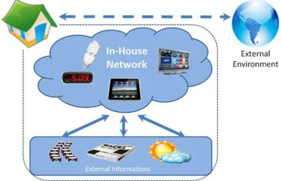
1.1 Motivating Scenario: Home automation . . . 1
1.2 Problem : Integration of heterogeneous service networks . . . 4
1.3 Work methodology . . . 6
1.4 Dissertation Outline . . . 9
2 Related Work : Study of e-Services integration approaches 11 2.1 State of the Art review . . . 11
2.1.1 IBM’s Web Services Gateway . . . 12
2.1.2 Mulesoft Web Service proxy . . . 13
2.1.3 Membrane Reverse SOAP Proxy . . . 14
2.1.4 JXTA and Web Service Gateway . . . 15
2.2 Synthesis . . . 16
2.3 Advancement . . . 18
3 Integration Bridge between heterogeneous service networks 21 3.1 Concept . . . 21
3.1.1 Service Publish/Look-Up Interoperability Bridge . . . 22
3.1.2 Service Invocation Bridge Service . . . 24
xiv CONTENTS
3.1.4 Overall concept . . . 26
4 Testing and Validation 29 4.1 Testing Methodology . . . 29
4.2 Proof of Concept Implementation . . . 32
4.2.1 NoN-MiddleWare . . . 32
4.2.2 WSDL to P2P e-service . . . 33
4.2.3 JAVA to Consumer Stub . . . 34
4.2.4 GUI Consumer . . . 35
4.3 Test Definition and Execution . . . 36
4.3.1 Publish and Look-up . . . 36
4.3.2 Service invocation . . . 37
4.4 Verdict . . . 38
5 Conclusions and Future Work 41 5.1 Future Work . . . 43
List of Figures
1.1 Motivating Scenario. . . 3
1.2 Different services environments integration. . . 4
1.3 Research Methodology (based on 1231212312 . . . 8
2.1 IBM Web Services Gateway general Concept (based on 1231212312 . . . 12
2.2 Mulesoft Web Service proxy general Concept (based on 1231212312 . . . 13
2.3 Membrane Reverse SOAP Proxy general concept 1231212312 . . . 14
2.4 JXTA and Web Service Gateway Concept 1231212312 . . . 15
3.1 Interoperability Bridge. . . 22
3.2 Interoperability Bridge sequence diagram. . . 24
3.3 Bridge service . . . 25
3.4 Bridge service sequence diagram. . . 26
3.5 Integration concept . . . 27
3.6 Integration Concept sequence diagram. . . 28
4.1 Global overview of the conformance testing process 1231212312 . . . 30
4.2 Proof of concept implementation. . . 32
4.3 Example of WSDL document. . . 34
4.4 Example of WSDL document transformation into JAVA document. . . 34
xvi LIST OF FIGURES
List of Tables
2.1 Related technology synthesis. . . 17
4.1 Example of a TTCN-based table. . . 31
4.2 Example of test case. . . 31
4.3 Publish and Look-up test definition. . . 36
4.4 Publish and Look-up test execution. . . 37
4.5 Service invocation test definition. . . 38
1
Introduction
This is the first chapter of this thesis, from this chapter a road can be made towards the following chapters, making this introductory chapter as a starting base into the development of this thesis. It begins with a framework of this thesis in a motivating scenario, in order to get to the problem that surrounds this work. This chapter ends showing a work methodology by which this thesis is guided, and leads us to obtain results that are in accordance with what was expected in the beginning.
1.1
Motivating Scenario: Home automation
In these days is hard to live normally without having to rely on some kind of technology. Tech-nology is everywhere and used in different ways by all kinds of people in different work areas. The fact that computers are more powerful, as well as the fact that everyday household appliances begin to have the capacity of networking, is changing the way that household appliances in the future will interact with houses.
1. INTRODUCTION 1.1. Motivating Scenario: Home automation
All these devices found at home need a way for connecting themselves, in order to communicate with each other. There are several technologies that can form networks of appliances, where each device is responsible for laying their own resources. Examples of current domotic protocols are X10, Konnex, CEBus and P2P, that support various communication standards (Ethernet, FireWire, Bluetooth, ZigBee, IrDA and proprietary buses) (Miori, Russo, & Aliberti, 2010).
• In the market, the most common systems use the X-10 protocol for being more economic, but the major disadvantage is its low robustness and to be very rudimentary. Systems that use this protocol are easily found by using the grid as a mean of communication, do not require experienced installers, or installation of additional wiring because the existing electrical installation is used (SMARTHOME, 2012);
• A more reliable and widely used protocol in existing home market, is the Konnex. The Konnex protocol has been developed within the context of the European Union, in order to cope with the existing home automation products in America and in Japan. The KONNEX allow the use of various physical means, the most used is the twisted pair, where all devices are connected to a Bus (Sakellaris, 2008);
• The CEBus (Consumer Electronics Bus) is a very complex and powerful protocol. It is a protocol that follows the OSI model incorporating the physical, logical, network and appli-cation (there are levels of transport, session and presentation). The CEBus protocol is very ambitious, which is noticed immediately by the media supported: grid, twisted pair, coaxial cable, infrared, radio frequency and optical fiber (Evans, 2001);
• The Peer-to-Peer (P2P) is a different way to share resources on a network. The way the participants interact and communicate on the network, as well as the services are provided and accessed is quite interesting. Therefore P2P technology is a strong possibility to solve problems inherent in automated home networks. The benefit of P2P is the ability to share services without the expense involved in maintaining a centralized server, instead of that, information can be exchanged between network peers. So the fact that P2P technology is very flexible, means that it can be used at different levels and with different purposes in home networks.
With these technologies, take for instance the possibility of connecting house sensors to other indoor devices, so that the devices can exchange data in a way that they can significantly improve the power consumption of houses. We could also use this type of technology between computers or even other more advanced devices so that they will share resources and use the computing power even if they are in energy saving, because there would be a lot less energy wasted in a house (Turcan, Graham, & Hederen, 2001).
1. INTRODUCTION 1.1. Motivating Scenario: Home automation
Being able to use shared resources in a network, can help to provide access to a greater amount of services to the network, and this way increase the quality of services provided. There are several types of services that can be accessed through the Internet that can help a daily average citizen. There are examples of existing services on the Internet, that could help with daily tasks.
The meteorology service can be quite useful in everyday life of any citizen. If a device that has Internet access and manage to reach a meteorology service and put it on the network. This way, every day when people left home, they were already prepared for the adversity weather could create. This service could however be linked to another, that would advice a type of clothing for use that day, and thereby increasing the amount of time to do other tasks before going out, or give a few more hours of sleep.
A traffic service is another service that could be quite important for a citizens who need to use the car every day to go to work. Instead of wake up, and have to turn on the radio or television and be aware of the news about the traffic, the service could automatically wake you up at a certain time (user defined) the individual, with the traffic information for the route that will be made by the service user. The service would give the best possible route to its destination. Therefore gaining some time on the itinerary and also in the wake up.
Other example, a service that will search every day in the covers of the newspapers of our prefer-ence and put them on a PDA or something else. Or even to the main news of the day. This way it is easier for us to wake up and see all our favorite newspapers while enjoying the breakfast. With such a infinity of services found in the Internet world, will be quite easy to improve the comfort of houses. In order to further improve the system, if it brings together two or more services, one more compact is created, that could help to better respond the daily tasks of an ordinary citizen.
1. INTRODUCTION 1.2. Problem : Integration of heterogeneous service networks
1.2
Problem : Integration of heterogeneous service networks
It is normally difficult to join different technologies, so it must be found a way to make the two service networks environments communicate. In an automated home environment, a network in which various types of technological elements will be connected and interact with each other. These elements have to be prepared for when needed, be able to get external services to further improve the house quality of services. These external services, often use languages that are inter-operable with those services used in the network, and as known there are several types of services over the Internet. This can raise some interoperability problems between the two environments.
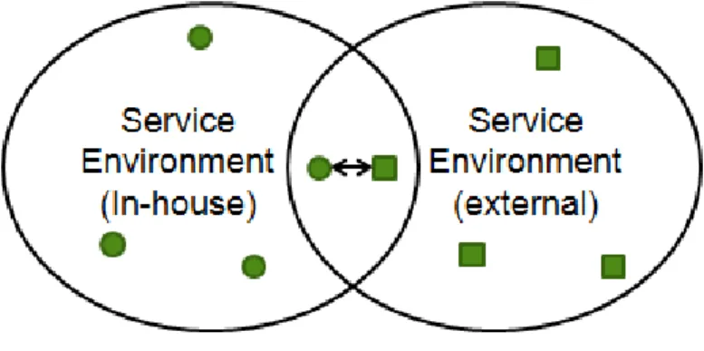
Figure 1.2: Different services environments integration.
On one hand, this lead us to the existence of problems due to the fact that they deal with different service technologies. These technologies use different languages, different protocols, different data types, different semantics, or systems that are not made for the same purpose. The fact that two different systems can work together, causes that the problems of heterogeneity may become larger. As known, standards have a key role in interoperability between systems. It must be reach an understanding, with the standards used, the two environments can work properly and interoperate themselves.
Then on the other hand, there are several integration approaches between systems, that can help to overcome problems that may occur in many different situations. The purpose of these approaches is to facilitate the communication, when design problems appear and different technologies inter-act. These integration techniques include adapters, bridges, proxy, mediators, facades and brokers (Eriksson, Reza Feizabadi, & Zamani, 2001).
• Starting with the adapter, which can transform an interface of a class, into one that is ex-pected by the customer. Thereby making it possible, that classes with different interfaces, communicate with each other. This way the client requests are made to the adapter instead being made to the original class. What the adapter makes is to translate the request, so that it is understood by the original class, then this translation is sent to the class;
1. INTRODUCTION 1.2. Problem : Integration of heterogeneous service networks
• A bridge is used when it is desirable that an interface (abstract) may vary independently of their implementations. This makes implementation not directly connected to the interface. So in this way with the use of a bridge makes the implementation code is changed, it is not necessary to change the interface. Therefore it can be said that the bridge causes the interface and its implementation are independent of each other;
• A proxy can function as a substitute for another object. Therefore a proxy mode can be seen as an intermediate which manages communications with a target. The proxy design pattern is widely used in infrastructures for distributed systems to represent remote components. The access to this target can consequently be controlled, and the proxy interface will be identical to the target, not knowing the client if is communicating with the target itself;
• The mediator acts as a central unit that can control various objects. Will function as an intermediary between the objects, without the objects having to interact with each other. Objects only know the mediator, which acts as a central hub. The objects have only one way to connect instead of being able to connect between all. This means that the components will be more loosely coupled to each other using a mediator, which facilitates easy replacement and reuse of components;
• The facade it is an object that provides a simplified interface to a larger piece of code that will be enough for most customers, the more sophisticated clients can look inside the facade. Customers to interact with components, send a request to the facade, which indicates what is the appropriate part of the component to the client;
• The broker consists of six types of components (clients, servers, brokers, bridges, client-side proxies and server-side proxies). The server registers itself in the local broker and receives requests from clients, sending responses by the server-side proxy. The client implements the functionality and sends requests to the servers through the client-side proxy and receives responses and exceptions. Provides an interface for clients and servers, and transmits the requests from clients to servers and exceptions and responses from servers to clients. A bridge is used to smooth communication among different brokers.
1. INTRODUCTION 1.3. Work methodology
How to integrate heterogeneous service systems, dealing with the technology mismatch of both environments?
• How to deal with the technology mismatch of service invocation across worlds?
• How to deal with the technology mismatch of service publication/look-up between both worlds?
The first question deals with the technology mismatch of service invocation across worlds. And the other question deals with the technology mismatch of service publication/look-up between both worlds, i.e., the services must be available for users, as if it were an own network service. The service network environment required for this work will have a clear idea about the services that it will host. Will have to know the name of the service, what it does, how it is used, so that the network peers can use them in a quickly and somewhat effective way.
Regarding the first feature, technology mismatch of service invocation across worlds, it is not a new subject in the scope of technology. There are projects that approach the interoperability subject. State of the Art for Interoperability architecture discusses this matter. It addresses several technologies that manage a way to make interaction between different systems (Arne-Jørgen Berre, Axel Hahn, François Vermaut, Lea Kutvonen, Peter F. Linington, 2008).
The fact that two different technologies can be used, can benefit this work, because the advantages of both sides are going to be inherited, and avoid the disadvantages of the two technologies. In order to get services into a service network environment, the service provided outside the network, should be treated like a service network resource. So within the network will have a peer that will be able to ask the network (Consumer) and find out if a particular service is available within the network, and a a peer that will be able to provide an external service (Provider).
Regarding the second feature, for a external service to be available for use within the service network. First it is needed to put the service to "speak" the same language spoken in the service network environment. After that an announcement of the service will have to be made on the network so it becomes accessible to everyone in the service network. Network users will then be able to look for the services in the network. In order to publish the service, informations of the service will have to be used. These informations will help in service discovery within the network.
1.3
Work methodology
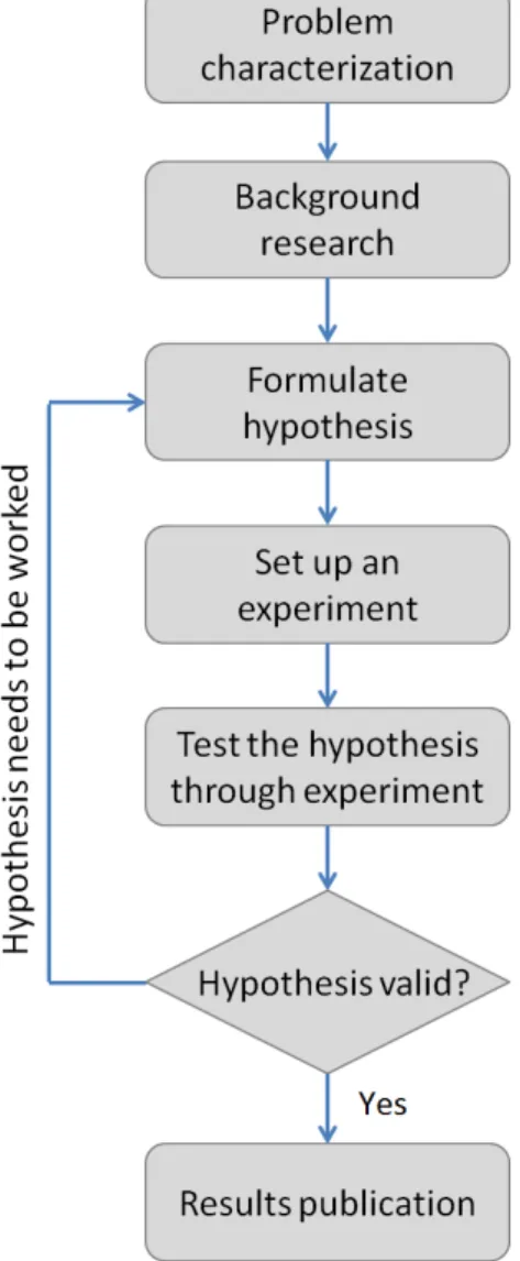
All thesis require a method by which to guide, i.e., the basic principles that will facilitate the achievement of an hypothesis for this thesis problem. It usually takes several steps in order to reach the final product, and these steps are represented in the figure 1.3 (Schafersman, 1994). The steps required to guarantee a reasonable work will be explained below in detail:
1. INTRODUCTION 1.3. Work methodology
Problem characterization
The initial work of this method begins with a detailed analysis of the whole concept behind what is needed for this work. This analysis will identify some problems, and a study is made on how to approach these problems, and can guide us to a question on which all our work will focus. This is a very important question that brings together two different technologies. The identified ques-tion in this work is How to integrate heterogeneous service systems, dealing with the technology mismatch of both environments.
Background research
This step is very important for our work, it consists in over-viewing several concepts that pro-ceeded this work. And this way, gather the best of each one and take a different approach to the subject in this work. The main objective of this work was to get a service that was outside the net-work, and make it available for peers to use the service as if it were part of the network. This way peers would have access to thousands of services that are scattered all over the Internet, making it easier for sharing resources within the same network.
Formulate hypothesis
It was made exhaustive research in similar areas that which affects this work. With this it will be given a chance to formalize the problem of this work. This hypothesis is very important because all our work will be based on this hypothesis. The hypothesis, must be able to respond to the issue raised before, just looking at it. This way it is known that the correct hypothesis for the problem is closer.
Set up an experiment
This stage is where is made the technological achievement of the hypothesis. This is done by implementing the specifications defined in it. When establishing the tests, it must be taken into account all the variables that may be necessary for the proper functioning of the scenario created for the problem. The implementation of this is meant to be used as proof of concept, in order to test the accuracy of hypothesis.
Test the hypothesis through experiment
The purpose of these tests is to evaluate the hypothesis by implementing a experimental solution for the concept behind our work, and then collect information that may be useful as metrics, behaviors and others. After gathering all this, the information will be confronted with the proposed objectives. These tests must be performed in a controlled environment, so there are no anomalies in the results obtained during the test.
Result Analysis and Conclusion
1. INTRODUCTION 1.3. Work methodology
If for some reason the tests fail, it can be said that the hypothesis proposed was not appropriate to the question that was made and then make a new formulation of hypothesis until it correctly answer the question. The conclusions in the end will be according to the results obtained after.
Results Publication
The final phase of this scientific method is the publication and exchange of information that has been obtained in this work. This exchange of information is very important so that all tests for the hypotheses are not made again. Thereby facilitating the evolution of the work done in the area, and help in the reformulations of hypothesis that tend to improve this work.
Figure 1.3: Research Methodology (based on (Schafersman, 1994)).
1. INTRODUCTION 1.4. Dissertation Outline
1.4
Dissertation Outline
This dissertation consists on five chapters. The first is the introduction of this dissertation. It begins by framing this work in a setting, that is motivating enough to investigate the matter in question. Thereafter it is to identify and characterize the problem, so it reaches the subject of research. Is defined then the method in which this work will be done.
The second chapter is the related work. It begins with a survey of existing solutions that can in some way contribute to solve the problem raised in chapter 1. After identification of some technologies, will be made an identification of each as well as a brief overview focusing on the problem. It will be made a synthesis that will end in a summary table, which will serve to be easier to understand how each technology approaches the problem. In the end a critical analysis is per-formed where it is made clear what the work will have to perform compared with the technologies previously spoken.
The third chapter is the hypothesis. In this chapter, based on information collected in the two previous chapters, is created and described a solution that aims at solving the problem found in chapter 1. This hypothesis is where all the work relies on, and based on the hypothesis, the implementation will be able to be built. From just watching the hypothesis, it can explain the whole mechanism that serves to address the problem. This solution begins with the conceptualization of the problem, followed by a specification where it will focus the subject in a more detailed manner.
The fourth chapter is the testing and validation. It begins with the definition of a validation method-ology that will be used to prove the hypothesis advanced. Next a proof of concept is made, where an explanation of the implementation is given and tests are performed. Then it is proceeded to the tests themselves, where a few tests are going to be defined, and then their execution will proceed. At the end a final verdict is given, and that points if the selected hypothesis for this problem was correct.
1. INTRODUCTION 1.4. Dissertation Outline
2
Related Work : Study of e-Services
integration approaches
This chapter refers to what has already been discovered about the subject in matter. This chapter will also serve to guide us to the concept, and will pick up on techniques/concepts/methods that can respond to parts of the problem. In addition, assists in improvement and development of new assumptions, concepts and paradigms.
Firstly will be made a survey of existing techniques that are able to answer the questions that are part of our problem, focusing on how this solutions could respond our problems. The second part will be a analysis of the problem, confronting then the solutions with the problem. This chapter ends with the progress that can be made on top of the technologies that are shown in this chapter. That is, show what good it can be withdraw from the technologies shown, and what it can be brought in order to further improve the new concept that this work will present.
2.1
State of the Art review
2. RELATEDWORK: STUDY OF E-SERVICES INTEGRATION APPROACHES 2.1. State of the Art review
2.1.1 IBM’s Web Services Gateway
The IBM Web Service Gateway is a platform that provides run-time configurable mapping based on WSDL documents. This platform will provide mapping of services, i.e., services can be ex-ported outside for consumption, and also be imex-ported as an internal service. For this it is used a gateway that acts as end-point. Services can be requested using a protocol, but can be invoked through another protocol. Using a gateway facilitates the use of UDDI registries, and that is good for publication and look-up of services. It is a secure technology because it provides a single point of control, access, and validation of web service requests (Holdsworth, 2002).
Figure 2.1: IBM Web Services Gateway general Concept (based on (Holdsworth, 2002)).
This platform uses the WSDL documents as mentioned earlier. In order to publish/look-up ser-vices, will have to first import the document to the gateway. The gateway will generate a new WSDL that will be shared. This new WSDL will have the gateway as the end-point service. This way the gateway can publish the service in UDDI registries. Anyone looking for services can use UDDI lookups in order to find the service.
In order to make the service invocation, the user must send a SOAP request to the gateway, and then is able to invoke the service within a firewall. The fact that this technology uses a gateway, it is quite good for bringing together two different worlds. This way it can smooth the incompatibility problems from these technologies that may appear. In the figure 2.1 is noticeable that someone sends a request by the gateway in order to make it to the destination. The Microsoft also had a technology that used the technique of integration gateway, but it was a little more complex than this, which did not benefit at all this work. Due to the fact that they are similar, only the IBM concept was referred.
2. RELATEDWORK: STUDY OF E-SERVICES INTEGRATION APPROACHES 2.1. State of the Art review
2.1.2 Mulesoft Web Service proxy
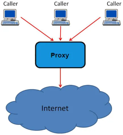
This concept is simpler than the previous one. It can not answer all the questions of this work, but either way is a valid concept as well. The aim of this concept is to act as an intermediary between an application and a target web service. This proxy may well introduce new behaviors in the process without being noticed.
This way you can add/remove HTTP headers, it can change the SOAP envelope to add/remove entries and change the WSDL so that these can call services within a firewall (MuleSoft, 2011).
Figure 2.2: Mulesoft Web Service proxy general Concept (based on (MuleSoft, 2011)).
2. RELATEDWORK: STUDY OF E-SERVICES INTEGRATION APPROACHES 2.1. State of the Art review
2.1.3 Membrane Reverse SOAP Proxy
This technology manages to expose services that are within a network, and make them available on the Internet. A client who is using a service through the reverse proxy, may think that is accessing the server, because a reverse proxy can pretend it is a server. It works for security reasons, because this way it can monitor traffic information between the client and the service network. The use of HTTP SOAP, is due to work directly on the application.
It may also reject requesting data, based on the request that arrives, and can also choose where to send requests to different internal deployment of services on different hosts. Although when viewed from the outside, appear to have been placed all in the same host. Once a client request has been sent to a given server, that server should respond to all subsequent requests from that client, and this is also managed by the reverse proxy (Membrane, 2008).
Figure 2.3: Membrane Reverse SOAP Proxy general concept (Membrane, 2008).
This reverse proxy is intended to expose services that are within a network and bring them to the Internet world (noticed in figure 2.3). This is a good way to expose services, but exactly the opposed to what is wanted. In this technology a network of services has a service, that would like to expose, and it contacts the reverse proxy that will serve as an intermediary for the end customer, without the customer know that sometimes is using the service through a reverse proxy. Once again it is dealt with the interaction of network services and Internet world, two distinct worlds that span multiple technologies. The reverse proxy also store information regarding the service, to make it easier for later use.
2. RELATEDWORK: STUDY OF E-SERVICES INTEGRATION APPROACHES 2.1. State of the Art review
2.1.4 JXTA and Web Service Gateway
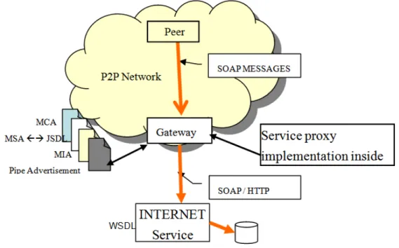
The goal of this project is to provide the convergence between Web Services and a P2P networks. This make it possible to use the services as it was an own P2P service. This way a P2P user can use a service, even if it is stored in the Internet. If the peer is in the Internet and wants to use a service provided by a network peer it could use it. Since the concept of both worlds (web service and P2P) overlap a little, but their present technology is slightly different (Schneider, 2001). The two technologies will complement each other to form a hybrid solution to this problem. This proposal rely on the existence of an intermediary, acting as a gateway between the two worlds. Thanks to the gateway, existing P2P services can be exposed as Web Services, and on other hand, Web Services existing outside the P2P network are exposed by the gateway and can be accessed (Sting & James, 2007).
Figure 2.4: JXTA and Web Service Gateway Concept (Sting & James, 2007).
2. RELATEDWORK: STUDY OF E-SERVICES INTEGRATION APPROACHES 2.2. Synthesis
This proxy stub is an object that represents the service in the JXTA network, and have the ability to communicate with other network resources. This proxy stub will be advertised in the network, making it accessible to other peers. This proxy stub uses SOAP to communicate with the Web Services, but the client does not need to understand it. Resources like peers, peer groups and the services published by peers in JXTA network are described using advertisements. Peers discover each other, and the resources available in the network, that were provided by network peers, can be searched by looking in the network advertisements.
2.2
Synthesis
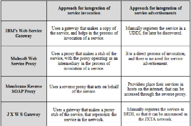
Now that all concepts were discussed, it is time to approach how these concepts directly address the problem of this work for each of the features found for our work. All the concepts presented above approach the subject in different ways. Reminding the features referred earlier that are necessary for our work: The technology mismatch of service invocation across worlds and the technology mismatch of service publication/look-up between both worlds.
Regarding the fact that there may be differences of language in relation to those who consume and provides the service. All technologies have their own way to solve this problem. The JXWS gateway and the IBM Web Service Gateway use both a gateway to try to resolve interoperability problems that may arise from the joining of two worlds that can be different. The technologies used in these two cases, are used in order to be able to translate protocols. The Gateway will also be responsible for forwarding requests to arrive so that they reach the final destination.
The IBM Web Service Gateway will use WSDL documents and will serve as the endpoint of the service, communication with the gateway is via SOAP requests. JXWS The Gateway will also use the WSDL documents and all communication between peers and the gateway is through SOAP. In this concept, the gateway is for placing the services within the network of P2P services, serving as a bridge between the network and the outside world.
Another way to interact different technologies is through a proxy, and the Mulesoft Web Service proxy is responsible for this. A proxy may optionally change the client request or server response, and sometimes can provide this feature without even connecting to the server requested. If a client wants a particular service, it first contacts the proxy that will serve as a intermediary for the communication. This creates a proxy stub of the service that may be changed according to what the client wants.
Other concept presented to bring together different technologies, is the Membrane Reverse SOAP Proxy. It is a concept that through it, can expose services outside the network. Therefore the client does not have to worry about safety issues and traffic because the reverse proxy will smooth all these problems.
2. RELATEDWORK: STUDY OF E-SERVICES INTEGRATION APPROACHES 2.2. Synthesis
In terms of service publishing, for the consumer look-up. The JXWS Gateway uses a technique that is intrinsic within the JXTA platform. This is the gateway will put informations about the service within the SRDI, which is nothing more than an index of all the resources that lie within this network of services. This way the search mechanism of JXTA can easily find any services desired by the customer.
The IBM Web Service Gateway will use a UDDI repository. In this repository is where are placed copies of documents with the WSDL endpoint of the gateway. Therefore in this concept the advertisement is made in this repository, which then makes it easy for the look-up of services, with the use of the UDDI search engine. The Mulesoft Web Service proxy makes no advertisement. It is a concept that is only used for service invocation through a proxy, without the client having to directly access the service.
Membrane SOAP Reverse Proxy has a slightly different concept. This technology is for those who want to provide a service. Therefore the advertisement of a service is made on a host chosed by the reverse proxy, over the Internet. This way a client that wants a service accesses a host on the Internet and uses a service through the reverse proxy as if it was the server. In table 2.1, a synthesis of the above technologies is shown.
2. RELATEDWORK: STUDY OF E-SERVICES INTEGRATION APPROACHES 2.3. Advancement
2.3
Advancement
From the technologies researched some conclusions were drawn that can benefit this work. This way, with the analysis of four different techniques that interact with services, a reflection can be made in order to get a good approach related to our problem. This way there will be a critical analysis of the problem based on the technologies described previously.
Regarding the techniques of integration used for the interaction between the two worlds. The IBM Web Service integration technique used a gateway. It will act as a bridge that connects an internal network to the outside world. Both worlds can put services for consumption in the network. This concept is well developed but is not exactly what is intended for this to work. Because with this concept peers must interact with the gateway to use a service, and in this work the gateway should have a more transparent work, and automatically make the consumer and provider communicate. The JXTA and Web Service gateway also uses a gateway, but in this case bringing together the world of P2P services with the world of web services. This concept has much potential, but fails to have an implementation associated with it. Anyway this gateway concept is close to what is necessary for this work. The Mulesoft Web Service proxy is a concept that will use a proxy, which acts as an intermediary in calling a web service. In fact this concept will not differ greatly from the gateway used by IBM, in terms of concept associated with the technology. Despite being much less complex than the IBM, and serve only to not connect to the service directly. In terms of interaction between two worlds this concept does not add much to this work. The Membrane Reverse SOAP proxy is a concept that uses a reverse proxy. This concept is identical to what this work proposes, but the purpose is otherwise. With this technology the services that are available on an internal network can be exposed to the Internet. This work will have to use something like the reverse proxy but that works in the opposite direction, i.e., expose Internet services like network services.
So after analyzing the different integration techniques, it is reached the conclusion that it is needed something between the gateway and the reverse proxy. Something that will be similar to the reverse proxy but will provide a protocol conversion so that the client and server can communicate, even if the two use different protocols. The fact that this service work as a bridge between two worlds it can be called bridge service.
Regarding the way to make the service available on the network. Not all the technologies men-tioned earlier support this capability. The IBM Web Service gateway does this manually with the help of the gateway, a copy of the WSDL of the service is exported to the gateway and can be stored in a UDDI registry. Save the necessary information inside a UDDI registry can be good for this work, because it facilitates the look-up for services by the consumer. The fact that the services must be imported into the gateway can be harmful because if there is a problem with the gateway, these services are no longer available.
2. RELATEDWORK: STUDY OF E-SERVICES INTEGRATION APPROACHES 2.3. Advancement
The Mulesoft Web Service Proxy despite not advertise the service address, and be a completely manual concept. uses the technique of creating a stub for a service, which is nothing more than an adapter, which serves to assist in communication between two different entities. This stub, works like the service, but with the features that the client wants. For this work may be important, because not always all the features of services are needed. With this, there would be no unnecessary expenses in the network memory.
The JXTA and Web Service Gateway is a junction of these two latest technologies mentioned. Manually with the help of gateway it is created a proxy stub service. Then put the information in a JXTA register, which is called SRDI. The gateway will handle the entire process of the service publication within the network. This idea is closer to what is required for our work. For this work, it will require a more automated mechanism. The Membrane SOAP reverse proxy also works manually, this means that when a provider wants to expose your service, it contact the reverse proxy to do so. But in this case the service is exposed to the Internet, therefore making the exact opposite of what our work is intended.
2. RELATEDWORK: STUDY OF E-SERVICES INTEGRATION APPROACHES 2.3. Advancement
3
Integration Bridge between
heterogeneous service networks
In this chapter, the work concept will be created, in accordance with our goal to unite the two different service environments. The data collected in the previous chapter will be used, so it can help to put our concept into practice. Firstly it starts with a more general concept which covers the work of in a more simple way. It is also seen how all the objects interact among them, that will serve to observe how the work will have to be done in order to correctly answer the problem. So that someone who looks at this work concept, can easily abstract the solution shown.
3.1
Concept
3. INTEGRATIONBRIDGE BETWEEN HETEROGENEOUS SERVICE NETWORKS 3.1. Concept
For each feature, it is shown the interactions between the various components, beginning with a sequence diagram for the registry/look-up of services, and then moving to the sequence diagram for the invocation of the service. These will help to clarify the sequence in which each task must be performed. With this sequence diagram, it may be withdraw other conclusions about the concept which was not otherwise possible with only the overview concept presented.
These interactions will serve to guide the practical implementation of this work, functioning as a map that will help to know what to do at each point of the work. A good specification is halfway to a successful implementation. Finally, an overall concept is also shown, as the final sequence diagram, where it is notorious that each task must be done in their time, so that the whole process occur in the best way possible.
3.1.1 Service Publish/Look-Up Interoperability Bridge
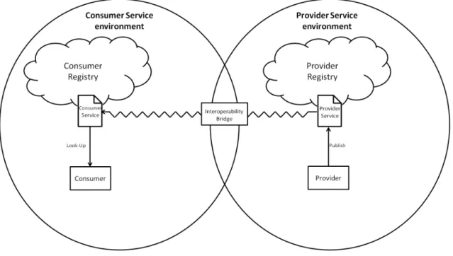
As stated earlier, the advertising of services is very important because the consumer is then able to find the service needed and then invoke it. So without the publication of the service there would be no service invocation. With the help of an Interoperability Bridge, an interaction of the service consumer networks environment, with external services can be provided. With this any information from a service provided can be pulled into a consumer service network. This makes that any consumer connected to a service network, can search for the service as needed. In order to make interact the two different environments, each service provided must be treated as a service resource in the service network.
Figure 3.1: Interoperability Bridge.
3. INTEGRATIONBRIDGE BETWEEN HETEROGENEOUS SERVICE NETWORKS 3.1. Concept
As represented in figure 3.1, it shows a consumer and a provider of services as well as two repos-itories, one in the consumer network, and another one on the provider network. The provider that appears in the figure can reach for external services (e.g. Internet, local drive), and make it acces-sible within the consumer service network. There is a consumer that searches in the network for a service that wants to access, and searches for it in the network repository. There is two registries that need to communicate in some way, the provider registry is where the services are hosted in a external environment, and the consumer service registry is where the service is going to be hosted in order to be used in the consumer network.
The service will initially only be prepared to be accessed via those who understand the technology used by the provider environment. With the help of Interoperability Bridge, the service will be ready to be looked-up by service network consumers. To make the translation of the service informations between one world to another, an engine will be used to treat this interoperability. In order to a provider publish a service, the service informations have to be deployed in the repository by the Interoperability Bridge, where the information of the service (method name, parameters and the return type) has to be extracted for later use, and stored in the network. This mechanism will make the network environment to be able to recognize the service, as if it were a service of the consumer network itself.
3.1.1.1 Interaction
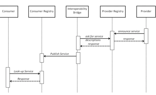
The first feature will be explained by the sequence diagram of the publication/look-up of a service, and is shown in figure 3.2. Firstly there must be a service provider, which will have to put his service in a given service environment registry. Therefore it must publish his service so that it is accessible to others who wish to use it. This service will be published in the provider environment, becoming immediately available for use by all who are able to understand the technology behind the environment in which this service is being held.
3. INTEGRATIONBRIDGE BETWEEN HETEROGENEOUS SERVICE NETWORKS 3.1. Concept
Figure 3.2: Interoperability Bridge sequence diagram.
After the publication process has been made, and found to be positive. Users who wish to look-up for a particular service within the consumer environment, can do it. In order to this look-up be made, a service consumer, will make the request for look-up in the consumer registry. If the type of services that consumers seeks is registered in this environment, the search result is then sent to the service consumer. And the process of service invocation can then proceed. This completes the process publication/look-up for a service. In which a service registered by a service provider (target service environment), that comes from a different environment used by a consumer (source service environment), be searched as if the new service belonged to the consumer environment.
3.1.2 Service Invocation Bridge Service
The fact that this is an invocation of services between two service environments, it can be extracted that it represents an intersection between the provider service environment and the consumer ser-vice environment, and there is a gap between them, that is filled by a bridge serser-vice in order to make them communicate each other. There is a service consumer and a service provider’, and the two are in the same service network, but one is providing an external service that comes in a different language (provider) that the consumer service environment use. Because of that, the two need to learn to communicate in some manner. This communication is made with the help of a bridge service that works like an interpreter, since the two need help to interact with each other.
Like it was said above, the bridge service manages the communication between the service provider and the service consumer to improve the quality of the service invocation. Each service consumer in the proposed architecture interacts with their bridge service peer installed on the same network. In figure 3.3 is shown the concept of using this bridge service between the consumer and the
3. INTEGRATIONBRIDGE BETWEEN HETEROGENEOUS SERVICE NETWORKS 3.1. Concept
Figure 3.3: Bridge service
provider, in which the bridge play two roles. From the perspective of the consumer, the provider’ is like the service image in the network, and from the perspective of the provider, the provider’ is the one who represents himself in the network. Since the consumer sends the request to the provider’ and receives the response from it, the bridge manages all the communications between the consumer and the provider.
3.1.3 Interaction
Now that the process publication/look-up was explained, the process of service invocation is going to be explained, knowing that some parts occur at the same time. This whole process is shown in figure 3.4, and as previously stated the service provider environment and the service consumer environment are different. So the service generator will need to deal with the fact that the two en-vironments use different technologies for communication, and the service need to speak a different language from its initial purpose.
So at the same time that the publishing of the service to the consumer registry is made, a new service will be created, so that it can be understood by service consumers of the consumer service environment. That is made with an image maker, that creates an image of the service provided. For that the service is hosted at the provider’, which will be the one that will represent the service provider within the service consumer environment.
3. INTEGRATIONBRIDGE BETWEEN HETEROGENEOUS SERVICE NETWORKS 3.1. Concept
Figure 3.4: Bridge service sequence diagram.
3.1.4 Overall concept
The junction of the two previous concepts, show the final integration concept. The figure 3.5 shows an overview of the whole concept behind the problem. It shows a wannabe provider that wants to provide a service, but the service is outside its range. Therefore the figure shows, the provider getting the service from an external source, and with the help of a mechanism for interoperability, may publish it in a consumer service network.
This interoperability bridge, is well noticed in the figure 3.5. This interoperability consists in two mechanism (interoperability bridge and bridge service). With the help of the interoperability bridge, the service informations can be published in the consumer registry. And with the help of a bridge service, a new service can be generated so that consumers can invoke services as their own consumer network services. This is something that the provider/consumer could not previously do, because the language that both the environments used are different.
It is also noticed in the figure that all communication goes through the provider’, which removes the gap between the two worlds. The provider’ causes the gap to be removed, making these two worlds, in a certain way different, to touch and become one. This makes that a consumer of services, can consume services that formerly could not consume, and it just need to contact the provider’, in order to get in touch with a service that this way is able to understand.
3. INTEGRATIONBRIDGE BETWEEN HETEROGENEOUS SERVICE NETWORKS 3.1. Concept
Figure 3.5: Integration concept
3.1.4.1 Interaction
3. INTEGRATIONBRIDGE BETWEEN HETEROGENEOUS SERVICE NETWORKS 3.1. Concept
Figure 3.6: Integration Concept sequence diagram.
4
Testing and Validation
The objective of this chapter is to test for whether the system complies with all the features pre-viously spoken. This test will try to find out errors in the implementation of the system through a process of experimentation. These tests are usually made in special environments, so that there are no variables that can detract in any way the test results. These tests cannot ensure that the im-plementation is completely correct, can only show that there are errors visible (Tretmans, 2001).
4.1
Testing Methodology
There are several methods for testing the quality of solutions, and each of them connected to a different field of application. The more accurate in this case was to find a more general method that. A method suited for this work was the international standard for conformance testing of Open Systems, also called ISO-9646, "OSI Conformance Testing Methodology and Framework" (Technology, 1991).
4. TESTING ANDVALIDATION 4.1. Testing Methodology
This standard defines a methodology and framework for protocol conformance testing, assuming that protocols are specified using a natural language. It was originally developed for OSI protocols, but due to its low usage it is also used for testing other kinds of protocols.
The conformance testing process consists of three parts (visible in the figure 4.1). The first part is represented by the specification of an abstract test suite to the defined system. This is referred by test definition. This test suite is abstract in the sense that tests are developed independently of any implementation. It is intended that abstract test suites of standardized protocols are also standardized. The second part consists on a definition of the tests, so that these tests are executed. This part is referred to as test implementation. The abstract test cases of the abstract test suite are transformed into executable tests that can be executed or interpreted on a real testing device or test system. The last part is the test execution, which consists in executing the tests and observing the results. All this leads to the final verdict of the system under test with the requirements initially set (Tretmans, 2001).
Figure 4.1: Global overview of the conformance testing process (Tretmans, 2001).
The fact that test suites are standardized causes them to be specified with a well-defined classifi-cation. For it is used a semi-formal language, TTCN-2 - Tree and Tabular Combined Notation.
4. TESTING ANDVALIDATION 4.1. Testing Methodology
In TTCN-2 the behavior of test cases is specified by sequences of input and output events that occur at the environment. Successive events are indicated by increasing the level of indentation, alternative events have the same indentation. A sequence ends with the specification of the verdict that is assigned when the execution of the sequence terminates.
Some alternatives will describe correct behavior, ending with the positive verdict success, while other alternatives describe erroneous behavior, ending with the negative verdict fail. The verdict inconclusive indicates correct but not intended acting.
Table 4.1: Example of a TTCN-based table.
An example of such tables is present in the table 4.1. Shows an example of how a phone call can be evaluated. First a user dials a number if there is no connection, the verdict is "Fail". If there is connection, and the call is established the verdict is "Success", if the call is busy then the verdict is "Inconclusive."
To show the results of the tests, a table of test cases has to be done. The table of test cases must contain the parameters of the tests that have to be made, including the necessary inputs as well as the expected results and the actual. The table 4.2 shows an example of test cases.
4. TESTING ANDVALIDATION 4.2. Proof of Concept Implementation
4.2
Proof of Concept Implementation
In this project the language chosen was Java, because it was used a NoN-MW that is based on the JXTA project (but with some added functionalities), which uses the Java language, and also a tool that transform WSDL documents into JAVA documents. As already stated in the previous chapter, based on the implementation, the implementation of this work can be performed. Since the specification is a general idea of how the process of this work must be carried out. In this implementation, there are several modules present, and all together constitute the entire system. All this work is based on the NoN-MW. Because it support a whole network of connected peers within a P2P network, and services can be supplied. The platform also uses the SOAP language, that is very useful for the communication between the peers inside the network. Having attention to the figure 4.2, the various modules are observable. Like the transformation of WSDL document into JAVA documents, and the creation of the consumer stub for the invocation (through a reflection process) and the NoN-MW, which deals with all things related to the P2P service network, and finally the GUI consumer, which is the interface responsible for showing all the modules working.
Figure 4.2: Proof of concept implementation.
4.2.1 NoN-MiddleWare
Starting with the first module shown in figure 4.2, perhaps the most important part of the whole system, because it is what makes this whole system move, and may even be said that is its core sys-tem. The NoN-MW is a platform developed by UNINOVA for the project FP7-216420 Cuteloop.
4. TESTING ANDVALIDATION 4.2. Proof of Concept Implementation
The aim of this platform is to provide a way that a device is introduced in a network, and com-municate over a virtual overlay network. Thereby getting all the devices connected to a Logi-cal BUS. This concept of network-of-networks was introduced by new middleware developments (ARTEMIS-100261 SIMPLE project), and involves the use of a multiple WSNs. So the NoN-MW, will allow communication and integration of devices, through different WSNs.
The NoN-MW focuses especially on two areas of technological support. One is networking and telecommunications and the other is supporting services and systems integration support. The first deals with the fact that can establish and manage a network, that hosts various devices, as well as dealing with communication between them. While the second handle the fact that can support services in the network, as well as aspects of the integration of different systems (e.g. RFID, sensors, LBS). Various types of devices can join the network, but have to comply with a set of rules to ensure success in the communication between all different types of devices. The NoN-MW does not need to run within each device, but needs at least to be among the device and the network. In the future it is expected that all devices are capable of running the middleware, even a lighter version in the case.
As stated previously, the NoN-MW is based on a reference implementation of JXTA. JXTA is to provide a basic set of underlying functions, whose main objective is to deliver various types of network services. This way the NoN-MW use basic functions of this platform to reduce the efforts of an entire new implementation of such features. Now that the middleware used in this work has been explained it can be used to create the peers involved as shown in figure.
4.2.2 WSDL to P2P e-service
Now it will be explained how the second module works. After having a peer who can represent the provider in the network (P2P Provider’). What the W3C provider has to do, is to pick up service off the Internet. Here is where the tool for transformation of the WSDL document enters. It is used in order to convert the Web Service file (WSDL document) into several JAVA document that can be interpreted by the NoN-MW platform. What this tool does is take the WSDL document that represents the service and generate the files needed to provide the service.
4. TESTING ANDVALIDATION 4.2. Proof of Concept Implementation
Figure 4.3: Example of WSDL document.
As is visible when comparing figure 4.3 with figure 4.4. The two codes have nothing to do with each other. But this way the NoN-MW platform can handle this service, as it complies with the language that this technology contains.
Figure 4.4: Example of WSDL document transformation into JAVA document.
4.2.3 JAVA to Consumer Stub
Now that the service has been passed to the most appropriate language, it can be published on the network, so that it can be invoked by a consumer peer. Now the mechanism of reflection, that appears in the specification of the concept enters. The figure 4.5 shows how the final service gets after a reflection being made.
4. TESTING ANDVALIDATION 4.2. Proof of Concept Implementation
This is a transparent process and the code gets allocated in memory, and the service becomes avail-able to be used by the client. After the reflection has been made, the invocation of the service may be given, with only the features that consumers found necessary. Note that before the invocation process can occur, a look-up process is done implicitly, making the invocation of the service can happen.
Figure 4.5: Example of reflection Stub.
4.2.4 GUI Consumer
Figure 4.6: GUI Consumer.
4. TESTING ANDVALIDATION 4.3. Test Definition and Execution
4.3
Test Definition and Execution
Tests now have to be defined, in order to yield a verdict that indicates whether the proposed solu-tion is in fact suitable for this work. The tests will be divided into two groups, each corresponding to a feature of this work, and must be in accordance with the implementation made, so that we can follow the order of the tests, in the implementation figure. The following tests were chosen:
1. Publish and Look-up -The first test is used to verify that the data types from the WSDL, are equal to the data types after the lood-up process are finished. Different data types to be created will test the ability of the system.
2. Service invocation -The second test is used to verify if the result of the invocation will be the expected. Will be used different data types, with different types of arguments.
4.3.1 Publish and Look-up
4.3.1.1 Test definition
The first scenario shows that the data type of a service does not change after its publication and discovery on the network. A service provider will get the WSDL document off the Internet, then JAVA documents are generated with the WSDL document. After that the consumer stub is generated, which will be at the end compared to the original file in terms of arguments and results result data type. The table 4.3 exemplify this test.
Table 4.3: Publish and Look-up test definition.
4. TESTING ANDVALIDATION 4.3. Test Definition and Execution
4.3.1.2 Test execution
As already stated, the test tables may submit more than one test. Therefore, the test for publication and look-up will be tested with various inputs to check that the actual results are in agreement with what would be expected, and this test is represented in table 4.4
Table 4.4: Publish and Look-up test execution.
The tests were run using different inputs, such as integers, strings, arrays. As expected current results were in agreement with what was expected, therefore tests were successful. Tests 1, 2 and 3 show that the data type is equal to the initial end type data obtained when all the transformations of the service occur. Test 4 shows the char data type from the WSDL and after the look-up process, appears with no result whatsoever. This occurs because the systems has some problems with arrays of data, the problem was fixed after this test done.
4.3.2 Service invocation
4.3.2.1 Test definition
4. TESTING ANDVALIDATION 4.4. Verdict
Table 4.5: Service invocation test definition.
4.3.2.2 Test execution
The tests were run using different inputs again, like shown in table 4.6. Tests 1, 2, 3 and 4 showed that the actual results when compared with the expected ones were equal, therefore the tests were successful. All tests were successful because the entire system is designed against failures, making it difficult to make the system fail.
Table 4.6: Service invocation test execution.
4.4
Verdict
The first conclusion that can be drawn from the tests, is that the proof of concept made, passed all tests except for one. With success, the service provider has got the service, and has put it at the disposal of the network to be discovered. Since the mechanism that translates the service for an appropriate language, does it correctly, passing all the service characteristics correctly. Tests for the invocation of the service, passing various types of argument also went well, with the final result as expected.
4. TESTING ANDVALIDATION 4.4. Verdict
Having regard to the first test. It have been tested different services that use different types of arguments. In order to test whether the language translation between one and the other was made correctly. Thereby an error was found, when the WSDL worked with arrays of data, there was conversion issue for JAVA. This problem was fixed, after having verified the existence of this error. Nevertheless the existence of the problem was found with the execution of the test, it was decided to reference it in this chapter. In the first test, the service translation is well made, and on the other hand, the implicitly look-up of services is also well made. Therefore it can be said that the two components of this test have a positive display.
Having regard to the second test. All the tests had a positive result. But this is due to the fact that previously have been detected error with the arrays. Otherwise it there would be trouble in testing the service that sort characters, as well as the service that choose the smallest number. The service publication is well made, and on the other hand, the service invocation is also well made. Therefore we can say that the two components of this test have a positive display likewise.
4. TESTING ANDVALIDATION 4.4. Verdict
5
Conclusions and Future Work
This work begins by giving emphasis the fact that the technology is increasingly needed in people life, and therefore be more and more evolved. The fact that people increasingly like to have their home prepared for a more effective use, knowing that their appliances are beginning to have ability to interact with each other. There are several protocols that support this type of interaction, such as X10, Konnex, CEBus, or P2P networks. All these home automation technologies are good to make interaction between various home appliances in a home network. The devices need to communicate between them in order to share resources in an easy way. Some of the technologies referred are able to do so, that is provide services between the network participants and this way opening horizons to a enormous world, which is the world wide web.
Then a problem arises: how to make the integration of a service network environment and exter-nal services to that environment? There are several types of integration techniques that are able to reduce the interoperability problem, that can arise from the junction of two different service environments. The integration techniques found are the most varied as possible, contemplating solutions such as adapters, bridges, proxy, mediators, brokers and facades. Since the two en-vironments do not communicate among themselves. The best thing to do here is to provide an interpreter, so that the two environments can communicate with each other. Once surpassed the language barrier, it has to make the services that passed between the two environments, equally function as if were originated in that same environment.